Page 2132 of 3000
DF–34DIFFERENTIAL – REAR DIFFERENTIAL CARRIER
DF
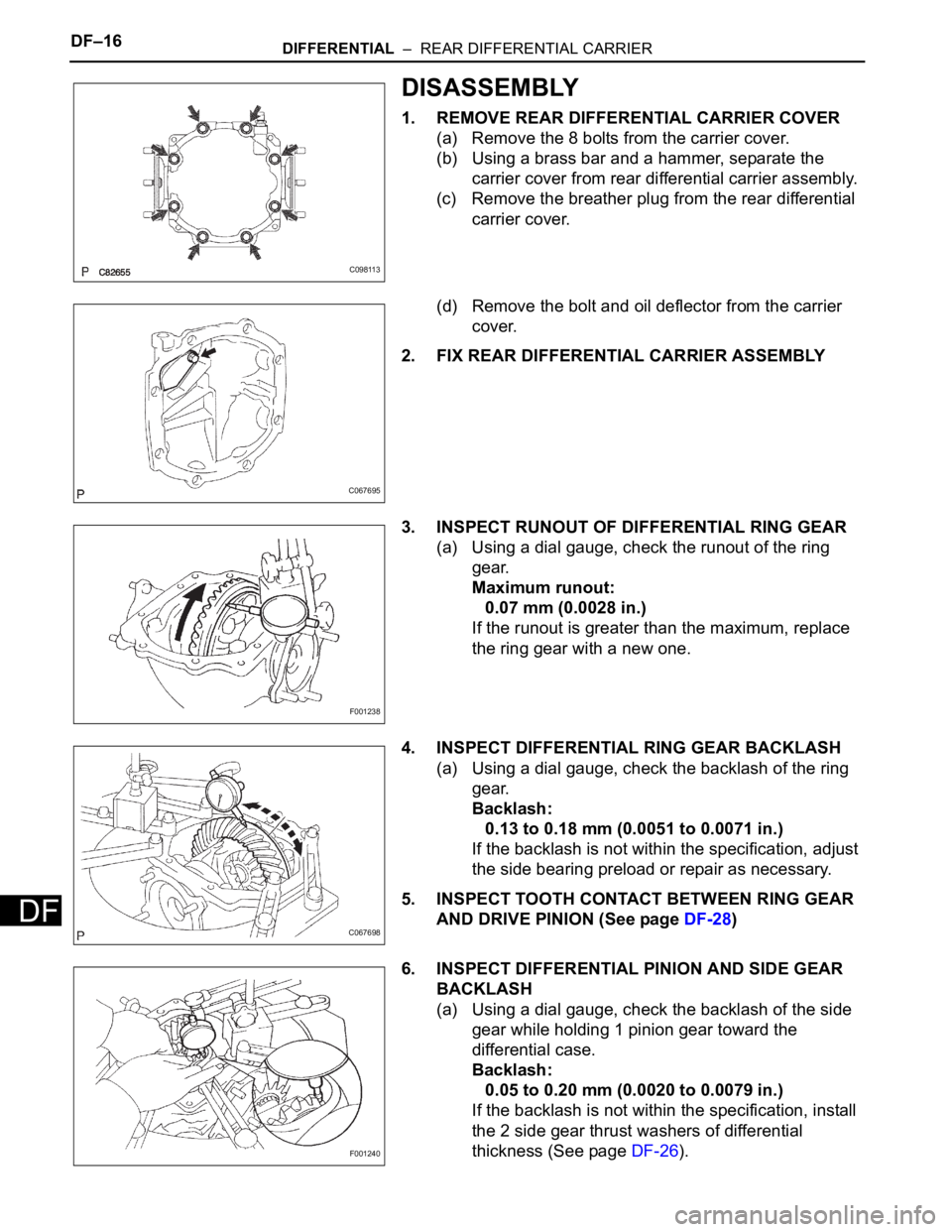
(e) Install the carrier cover with the 8 bolts.
Torque: 47 N*m (475 kgf*cm, 34 ft.*lbf)
C098113
Page 2133 of 3000
DIFFERENTIAL – DIFFERENTIAL OILDF–3
DF
DIFFERENTIAL OIL
ADJUSTMENT
1. INSPECT DIFFERENTIAL OIL
(a) Stop the vehicle on the level place.
(b) Remove the differential filler plug and gasket.
(c) Check that the oil surface is within 5 mm (0.20 in.)
from the lowest position of the inner surface of the
differential filler plug opening.
NOTICE:
• Excessively large or small amount of oil may
cause troubles.
• After replacing oil, drive the vehicle and
check the oil level.
(d) Check for oil leakage when the oil level is low.
(e) Install the differential filler plug and a new gasket.
Torque: 49 N*m (500 kgf*cm, 36 ft.*lbf)
D025304E19
Page 2134 of 3000
DF–8DIFFERENTIAL – REAR DIFFERENTIAL CARRIER ASSEMBLY
DF
DRIVE LINE
DIFFERENTIAL
REAR DIFFERENTIAL CARRIER ASSEMBLY
COMPONENTS
C159610E01
Page 2135 of 3000
DIFFERENTIAL – REAR DIFFERENTIAL CARRIER ASSEMBLYDF–9
DF
C159981E01
Page 2136 of 3000
DF–14DIFFERENTIAL – REAR DIFFERENTIAL CARRIER
DF
DRIVE LINE
DIFFERENTIAL
REAR DIFFERENTIAL CARRIER
COMPONENTS
C159699E01
Page 2137 of 3000
DIFFERENTIAL – REAR DIFFERENTIAL CARRIERDF–15
DF
C159679E01
Page 2138 of 3000

DF–16DIFFERENTIAL – REAR DIFFERENTIAL CARRIER
DF
DISASSEMBLY
1. REMOVE REAR DIFFERENTIAL CARRIER COVER
(a) Remove the 8 bolts from the carrier cover.
(b) Using a brass bar and a hammer, separate the
carrier cover from rear differential carrier assembly.
(c) Remove the breather plug from the rear differential
carrier cover.
(d) Remove the bolt and oil deflector from the carrier
cover.
2. FIX REAR DIFFERENTIAL CARRIER ASSEMBLY
3. INSPECT RUNOUT OF DIFFERENTIAL RING GEAR
(a) Using a dial gauge, check the runout of the ring
gear.
Maximum runout:
0.07 mm (0.0028 in.)
If the runout is greater than the maximum, replace
the ring gear with a new one.
4. INSPECT DIFFERENTIAL RING GEAR BACKLASH
(a) Using a dial gauge, check the backlash of the ring
gear.
Backlash:
0.13 to 0.18 mm (0.0051 to 0.0071 in.)
If the backlash is not within the specification, adjust
the side bearing preload or repair as necessary.
5. INSPECT TOOTH CONTACT BETWEEN RING GEAR
AND DRIVE PINION (See page DF-28)
6. INSPECT DIFFERENTIAL PINION AND SIDE GEAR
BACKLASH
(a) Using a dial gauge, check the backlash of the side
gear while holding 1 pinion gear toward the
differential case.
Backlash:
0.05 to 0.20 mm (0.0020 to 0.0079 in.)
If the backlash is not within the specification, install
the 2 side gear thrust washers of differential
thickness (See page DF-26).
C098113
C067695
F001238
C067698
F001240
Page 2139 of 3000
DIFFERENTIAL – REAR DIFFERENTIAL CARRIERDF–17
DF
HINT:
Measure the backlash of the side gear with the side
gear shaft installed.
7. INSPECT RUNOUT OF REAR DRIVE PINION
COMPANION FLANGE SUB-ASSEMBLY
(a) Using a dial gauge, measure the runout of the
companion flange vertically and horizontally.
Maximum runout:
0.10 mm (0.0039 in.)
8. INSPECT DIFFERENTIAL DRIVE PINION PRELOAD
(a) Using a torque wrench, measure the preload of the
drive pinion.
Torque: 0.6 to 0.9 N*m (6 to 9 kgf*cm, 5.2 to 7.8
in.*lbf)
9. INSPECT TOTAL PRELOAD
(a) Using a torque wrench, measure the total preload.
Torque: 0.3 to 0.5 N*m (3 to 5 kgf*cm, 2.6 to 4.3
in.*lbf)
10. REMOVE REAR DIFFERENTIAL SIDE GEAR SHAFT
SUB-ASSEMBLY
(a) Using needle nose pliers, remove the 2 snap rings
from the 2 side gear shafts.
(b) Remove the 2 side gear shafts.
F001237E08
SA02352
SA02352
C067701