Page 2681 of 3000

SR–8STEERING COLUMN – STEERING COLUMN ASSEMBLY
SR
DISASSEMBLY
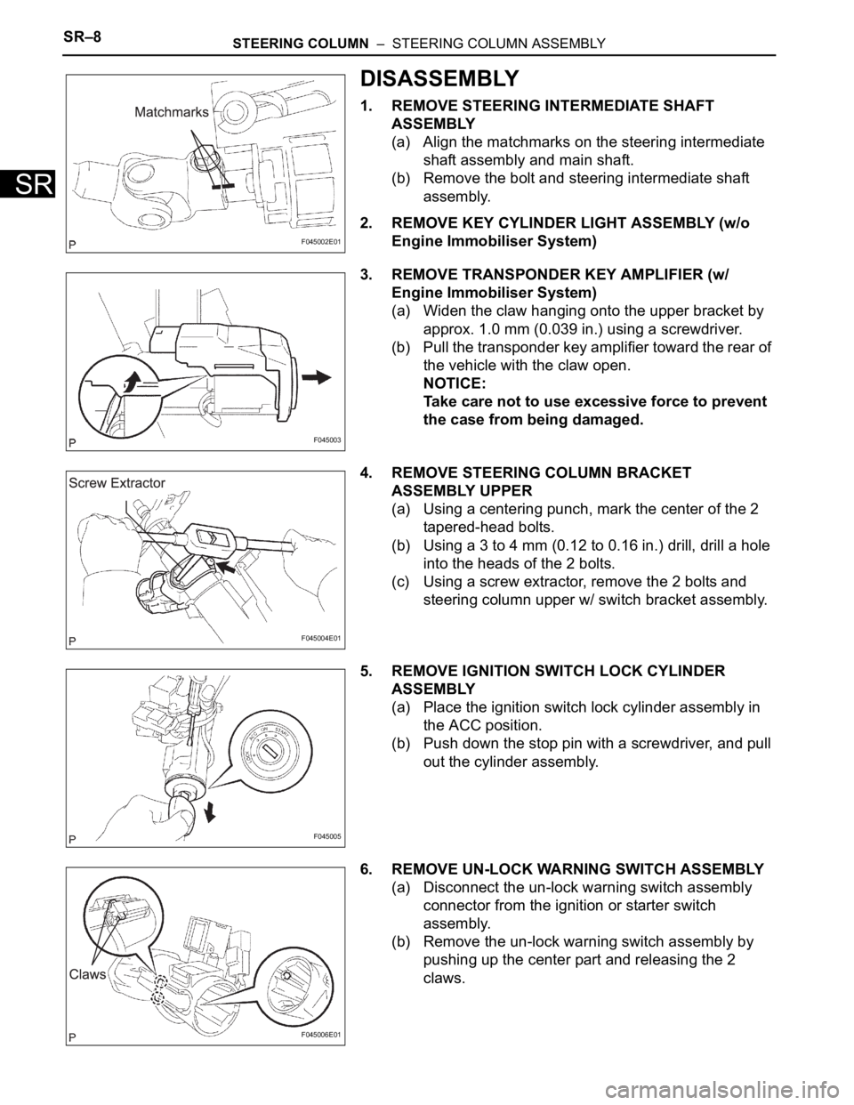
1. REMOVE STEERING INTERMEDIATE SHAFT
ASSEMBLY
(a) Align the matchmarks on the steering intermediate
shaft assembly and main shaft.
(b) Remove the bolt and steering intermediate shaft
assembly.
2. REMOVE KEY CYLINDER LIGHT ASSEMBLY (w/o
Engine Immobiliser System)
3. REMOVE TRANSPONDER KEY AMPLIFIER (w/
Engine Immobiliser System)
(a) Widen the claw hanging onto the upper bracket by
approx. 1.0 mm (0.039 in.) using a screwdriver.
(b) Pull the transponder key amplifier toward the rear of
the vehicle with the claw open.
NOTICE:
Take care not to use excessive force to prevent
the case from being damaged.
4. REMOVE STEERING COLUMN BRACKET
ASSEMBLY UPPER
(a) Using a centering punch, mark the center of the 2
tapered-head bolts.
(b) Using a 3 to 4 mm (0.12 to 0.16 in.) drill, drill a hole
into the heads of the 2 bolts.
(c) Using a screw extractor, remove the 2 bolts and
steering column upper w/ switch bracket assembly.
5. REMOVE IGNITION SWITCH LOCK CYLINDER
ASSEMBLY
(a) Place the ignition switch lock cylinder assembly in
the ACC position.
(b) Push down the stop pin with a screwdriver, and pull
out the cylinder assembly.
6. REMOVE UN-LOCK WARNING SWITCH ASSEMBLY
(a) Disconnect the un-lock warning switch assembly
connector from the ignition or starter switch
assembly.
(b) Remove the un-lock warning switch assembly by
pushing up the center part and releasing the 2
claws.
F045002E01
F045003
F045004E01
F045005
F045006E01
Page 2691 of 3000

PS–20POWER STEERING – VANE PUMP
PS
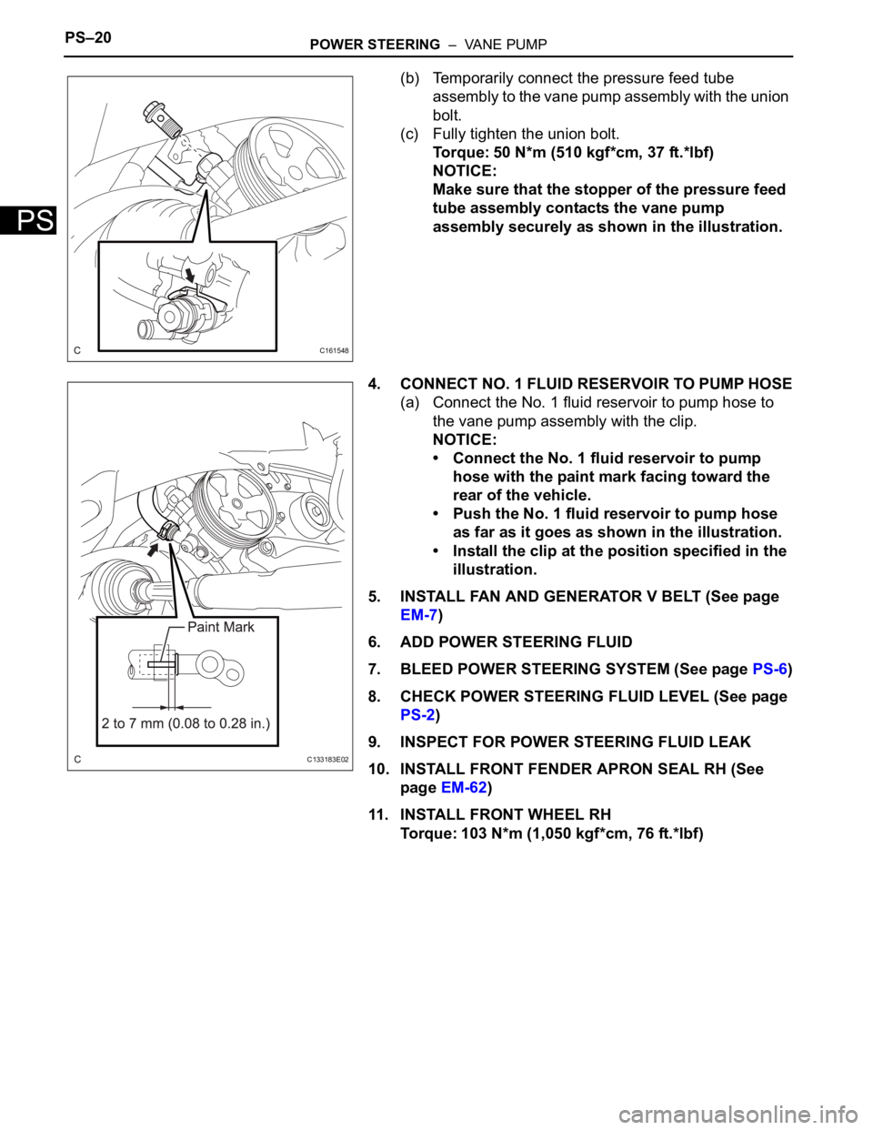
(b) Temporarily connect the pressure feed tube
assembly to the vane pump assembly with the union
bolt.
(c) Fully tighten the union bolt.
Torque: 50 N*m (510 kgf*cm, 37 ft.*lbf)
NOTICE:
Make sure that the stopper of the pressure feed
tube assembly contacts the vane pump
assembly securely as shown in the illustration.
4. CONNECT NO. 1 FLUID RESERVOIR TO PUMP HOSE
(a) Connect the No. 1 fluid reservoir to pump hose to
the vane pump assembly with the clip.
NOTICE:
• Connect the No. 1 fluid reservoir to pump
hose with the paint mark facing toward the
rear of the vehicle.
• Push the No. 1 fluid reservoir to pump hose
as far as it goes as shown in the illustration.
• Install the clip at the position specified in the
illustration.
5. INSTALL FAN AND GENERATOR V BELT (See page
EM-7)
6. ADD POWER STEERING FLUID
7. BLEED POWER STEERING SYSTEM (See page PS-6)
8. CHECK POWER STEERING FLUID LEVEL (See page
PS-2)
9. INSPECT FOR POWER STEERING FLUID LEAK
10. INSTALL FRONT FENDER APRON SEAL RH (See
page EM-62)
11. INSTALL FRONT WHEEL RH
Torque: 103 N*m (1,050 kgf*cm, 76 ft.*lbf)
C161548
C133183E02
Page 2731 of 3000

PS–20POWER STEERING – VANE PUMP
PS
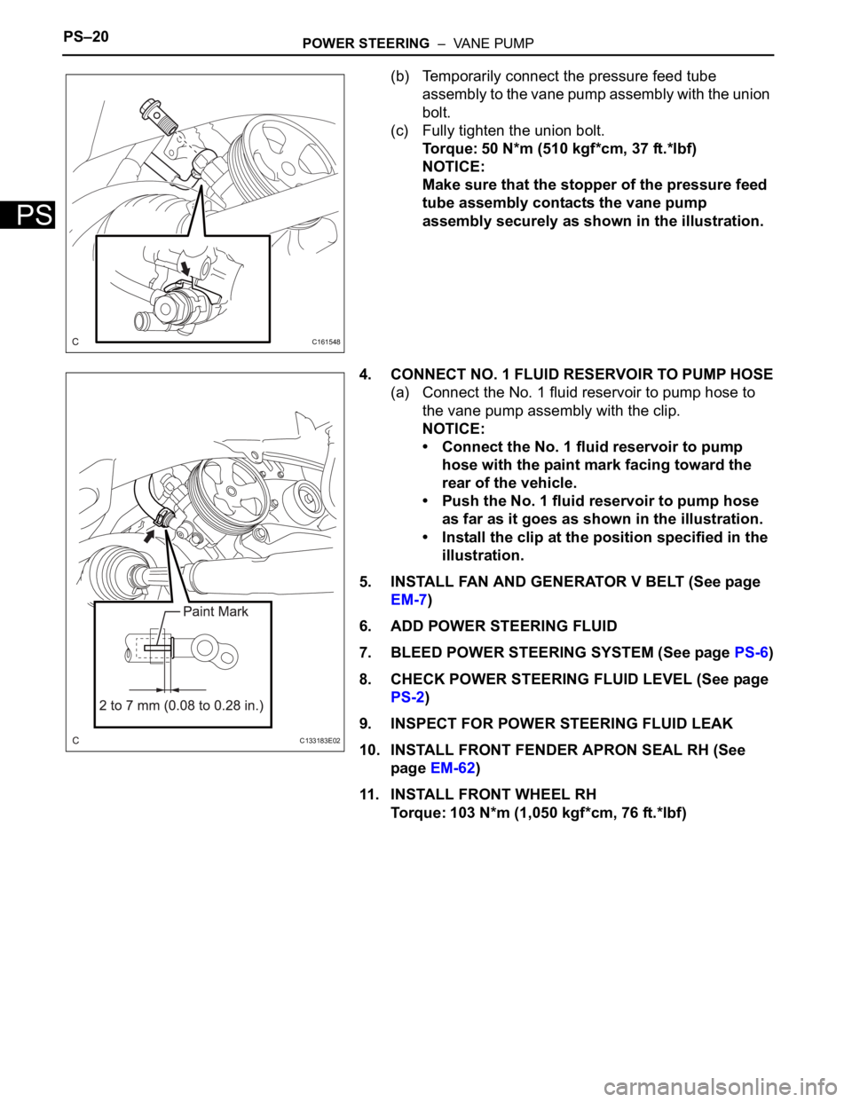
(b) Temporarily connect the pressure feed tube
assembly to the vane pump assembly with the union
bolt.
(c) Fully tighten the union bolt.
Torque: 50 N*m (510 kgf*cm, 37 ft.*lbf)
NOTICE:
Make sure that the stopper of the pressure feed
tube assembly contacts the vane pump
assembly securely as shown in the illustration.
4. CONNECT NO. 1 FLUID RESERVOIR TO PUMP HOSE
(a) Connect the No. 1 fluid reservoir to pump hose to
the vane pump assembly with the clip.
NOTICE:
• Connect the No. 1 fluid reservoir to pump
hose with the paint mark facing toward the
rear of the vehicle.
• Push the No. 1 fluid reservoir to pump hose
as far as it goes as shown in the illustration.
• Install the clip at the position specified in the
illustration.
5. INSTALL FAN AND GENERATOR V BELT (See page
EM-7)
6. ADD POWER STEERING FLUID
7. BLEED POWER STEERING SYSTEM (See page PS-6)
8. CHECK POWER STEERING FLUID LEVEL (See page
PS-2)
9. INSPECT FOR POWER STEERING FLUID LEAK
10. INSTALL FRONT FENDER APRON SEAL RH (See
page EM-62)
11. INSTALL FRONT WHEEL RH
Torque: 103 N*m (1,050 kgf*cm, 76 ft.*lbf)
C161548
C133183E02