Page 2076 of 3000
DRIVE SHAFT – REAR DRIVE SHAFT (for 4WD)DS–23
DS
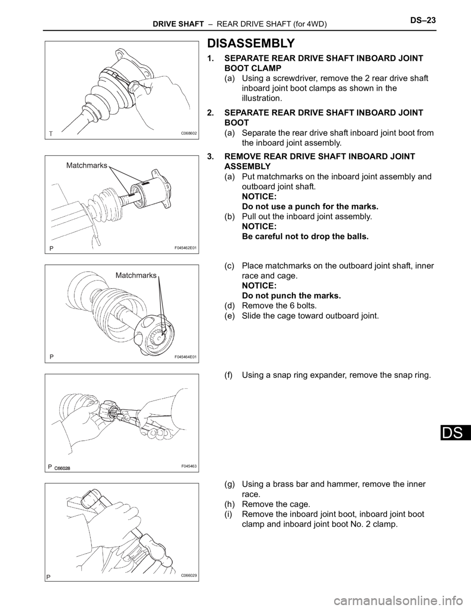
DISASSEMBLY
1. SEPARATE REAR DRIVE SHAFT INBOARD JOINT
BOOT CLAMP
(a) Using a screwdriver, remove the 2 rear drive shaft
inboard joint boot clamps as shown in the
illustration.
2. SEPARATE REAR DRIVE SHAFT INBOARD JOINT
BOOT
(a) Separate the rear drive shaft inboard joint boot from
the inboard joint assembly.
3. REMOVE REAR DRIVE SHAFT INBOARD JOINT
ASSEMBLY
(a) Put matchmarks on the inboard joint assembly and
outboard joint shaft.
NOTICE:
Do not use a punch for the marks.
(b) Pull out the inboard joint assembly.
NOTICE:
Be careful not to drop the balls.
(c) Place matchmarks on the outboard joint shaft, inner
race and cage.
NOTICE:
Do not punch the marks.
(d) Remove the 6 bolts.
(e) Slide the cage toward outboard joint.
(f) Using a snap ring expander, remove the snap ring.
(g) Using a brass bar and hammer, remove the inner
race.
(h) Remove the cage.
(i) Remove the inboard joint boot, inboard joint boot
clamp and inboard joint boot No. 2 clamp.
C068602
F045462E01
F045464E01
F045463
C066029
Page 2089 of 3000
DS–14DRIVE SHAFT – FRONT DRIVE SHAFT
DS
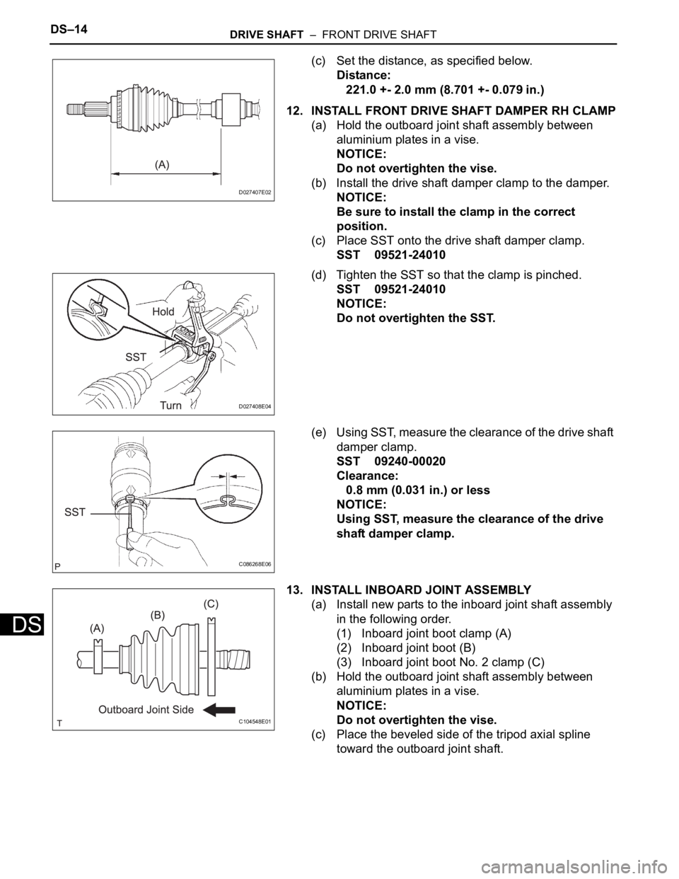
(c) Set the distance, as specified below.
Distance:
221.0 +- 2.0 mm (8.701 +- 0.079 in.)
12. INSTALL FRONT DRIVE SHAFT DAMPER RH CLAMP
(a) Hold the outboard joint shaft assembly between
aluminium plates in a vise.
NOTICE:
Do not overtighten the vise.
(b) Install the drive shaft damper clamp to the damper.
NOTICE:
Be sure to install the clamp in the correct
position.
(c) Place SST onto the drive shaft damper clamp.
SST 09521-24010
(d) Tighten the SST so that the clamp is pinched.
SST 09521-24010
NOTICE:
Do not overtighten the SST.
(e) Using SST, measure the clearance of the drive shaft
damper clamp.
SST 09240-00020
Clearance:
0.8 mm (0.031 in.) or less
NOTICE:
Using SST, measure the clearance of the drive
shaft damper clamp.
13. INSTALL INBOARD JOINT ASSEMBLY
(a) Install new parts to the inboard joint shaft assembly
in the following order.
(1) Inboard joint boot clamp (A)
(2) Inboard joint boot (B)
(3) Inboard joint boot No. 2 clamp (C)
(b) Hold the outboard joint shaft assembly between
aluminium plates in a vise.
NOTICE:
Do not overtighten the vise.
(c) Place the beveled side of the tripod axial spline
toward the outboard joint shaft.
D027407E02
D027408E04
C086268E06
C104548E01
Page 2098 of 3000
DRIVE SHAFT – REAR DRIVE SHAFT (for 4WD)DS–23
DS
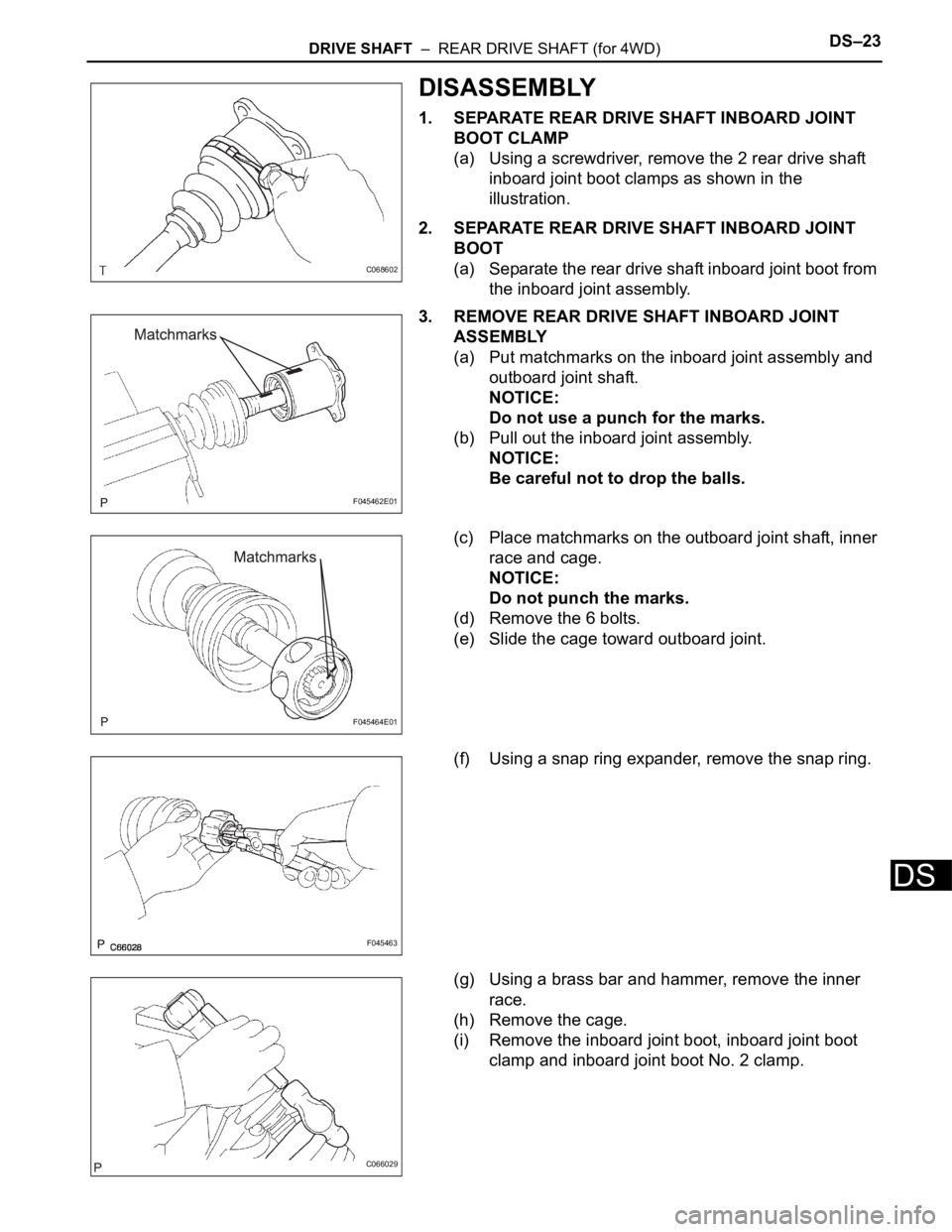
DISASSEMBLY
1. SEPARATE REAR DRIVE SHAFT INBOARD JOINT
BOOT CLAMP
(a) Using a screwdriver, remove the 2 rear drive shaft
inboard joint boot clamps as shown in the
illustration.
2. SEPARATE REAR DRIVE SHAFT INBOARD JOINT
BOOT
(a) Separate the rear drive shaft inboard joint boot from
the inboard joint assembly.
3. REMOVE REAR DRIVE SHAFT INBOARD JOINT
ASSEMBLY
(a) Put matchmarks on the inboard joint assembly and
outboard joint shaft.
NOTICE:
Do not use a punch for the marks.
(b) Pull out the inboard joint assembly.
NOTICE:
Be careful not to drop the balls.
(c) Place matchmarks on the outboard joint shaft, inner
race and cage.
NOTICE:
Do not punch the marks.
(d) Remove the 6 bolts.
(e) Slide the cage toward outboard joint.
(f) Using a snap ring expander, remove the snap ring.
(g) Using a brass bar and hammer, remove the inner
race.
(h) Remove the cage.
(i) Remove the inboard joint boot, inboard joint boot
clamp and inboard joint boot No. 2 clamp.
C068602
F045462E01
F045464E01
F045463
C066029
Page 2114 of 3000
DF–16DIFFERENTIAL – REAR DIFFERENTIAL CARRIER
DF
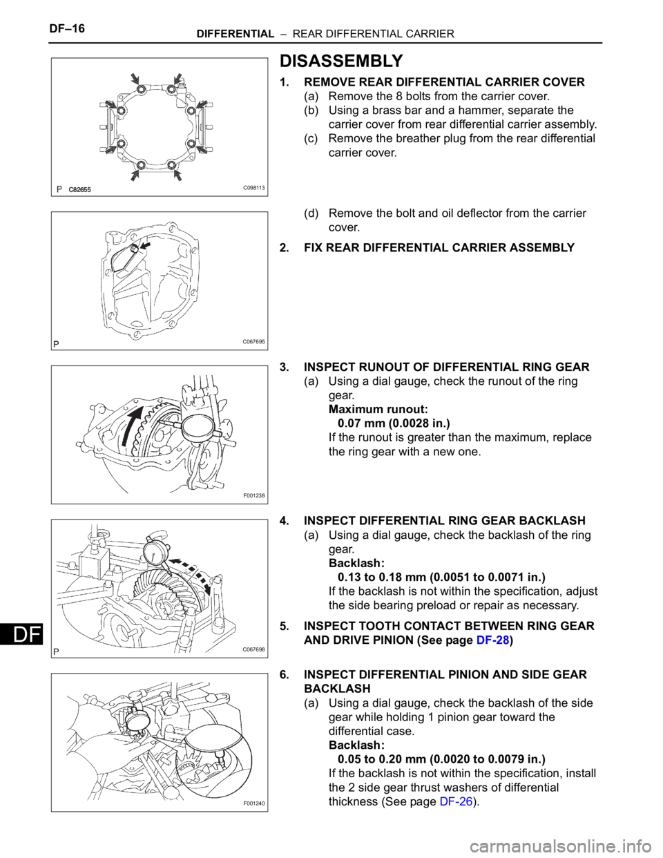
DISASSEMBLY
1. REMOVE REAR DIFFERENTIAL CARRIER COVER
(a) Remove the 8 bolts from the carrier cover.
(b) Using a brass bar and a hammer, separate the
carrier cover from rear differential carrier assembly.
(c) Remove the breather plug from the rear differential
carrier cover.
(d) Remove the bolt and oil deflector from the carrier
cover.
2. FIX REAR DIFFERENTIAL CARRIER ASSEMBLY
3. INSPECT RUNOUT OF DIFFERENTIAL RING GEAR
(a) Using a dial gauge, check the runout of the ring
gear.
Maximum runout:
0.07 mm (0.0028 in.)
If the runout is greater than the maximum, replace
the ring gear with a new one.
4. INSPECT DIFFERENTIAL RING GEAR BACKLASH
(a) Using a dial gauge, check the backlash of the ring
gear.
Backlash:
0.13 to 0.18 mm (0.0051 to 0.0071 in.)
If the backlash is not within the specification, adjust
the side bearing preload or repair as necessary.
5. INSPECT TOOTH CONTACT BETWEEN RING GEAR
AND DRIVE PINION (See page DF-28)
6. INSPECT DIFFERENTIAL PINION AND SIDE GEAR
BACKLASH
(a) Using a dial gauge, check the backlash of the side
gear while holding 1 pinion gear toward the
differential case.
Backlash:
0.05 to 0.20 mm (0.0020 to 0.0079 in.)
If the backlash is not within the specification, install
the 2 side gear thrust washers of differential
thickness (See page DF-26).
C098113
C067695
F001238
C067698
F001240
Page 2121 of 3000
DIFFERENTIAL – REAR DIFFERENTIAL CARRIERDF–23
DF
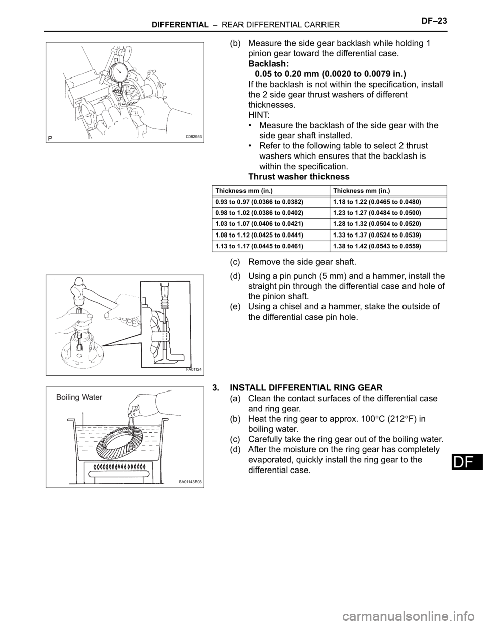
(b) Measure the side gear backlash while holding 1
pinion gear toward the differential case.
Backlash:
0.05 to 0.20 mm (0.0020 to 0.0079 in.)
If the backlash is not within the specification, install
the 2 side gear thrust washers of different
thicknesses.
HINT:
• Measure the backlash of the side gear with the
side gear shaft installed.
• Refer to the following table to select 2 thrust
washers which ensures that the backlash is
within the specification.
Thrust washer thickness
(c) Remove the side gear shaft.
(d) Using a pin punch (5 mm) and a hammer, install the
straight pin through the differential case and hole of
the pinion shaft.
(e) Using a chisel and a hammer, stake the outside of
the differential case pin hole.
3. INSTALL DIFFERENTIAL RING GEAR
(a) Clean the contact surfaces of the differential case
and ring gear.
(b) Heat the ring gear to approx. 100
C (212F) in
boiling water.
(c) Carefully take the ring gear out of the boiling water.
(d) After the moisture on the ring gear has completely
evaporated, quickly install the ring gear to the
differential case.
C082953
Thickness mm (in.) Thickness mm (in.)
0.93 to 0.97 (0.0366 to 0.0382) 1.18 to 1.22 (0.0465 to 0.0480)
0.98 to 1.02 (0.0386 to 0.0402) 1.23 to 1.27 (0.0484 to 0.0500)
1.03 to 1.07 (0.0406 to 0.0421) 1.28 to 1.32 (0.0504 to 0.0520)
1.08 to 1.12 (0.0425 to 0.0441) 1.33 to 1.37 (0.0524 to 0.0539)
1.13 to 1.17 (0.0445 to 0.0461) 1.38 to 1.42 (0.0543 to 0.0559)
FA01124
SA01143E03
Page 2138 of 3000
DF–16DIFFERENTIAL – REAR DIFFERENTIAL CARRIER
DF
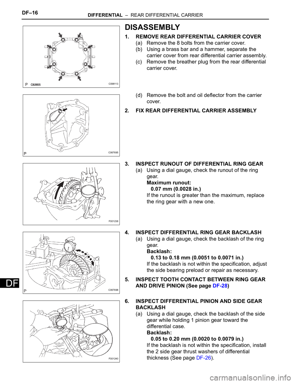
DISASSEMBLY
1. REMOVE REAR DIFFERENTIAL CARRIER COVER
(a) Remove the 8 bolts from the carrier cover.
(b) Using a brass bar and a hammer, separate the
carrier cover from rear differential carrier assembly.
(c) Remove the breather plug from the rear differential
carrier cover.
(d) Remove the bolt and oil deflector from the carrier
cover.
2. FIX REAR DIFFERENTIAL CARRIER ASSEMBLY
3. INSPECT RUNOUT OF DIFFERENTIAL RING GEAR
(a) Using a dial gauge, check the runout of the ring
gear.
Maximum runout:
0.07 mm (0.0028 in.)
If the runout is greater than the maximum, replace
the ring gear with a new one.
4. INSPECT DIFFERENTIAL RING GEAR BACKLASH
(a) Using a dial gauge, check the backlash of the ring
gear.
Backlash:
0.13 to 0.18 mm (0.0051 to 0.0071 in.)
If the backlash is not within the specification, adjust
the side bearing preload or repair as necessary.
5. INSPECT TOOTH CONTACT BETWEEN RING GEAR
AND DRIVE PINION (See page DF-28)
6. INSPECT DIFFERENTIAL PINION AND SIDE GEAR
BACKLASH
(a) Using a dial gauge, check the backlash of the side
gear while holding 1 pinion gear toward the
differential case.
Backlash:
0.05 to 0.20 mm (0.0020 to 0.0079 in.)
If the backlash is not within the specification, install
the 2 side gear thrust washers of differential
thickness (See page DF-26).
C098113
C067695
F001238
C067698
F001240
Page 2145 of 3000
DIFFERENTIAL – REAR DIFFERENTIAL CARRIERDF–23
DF
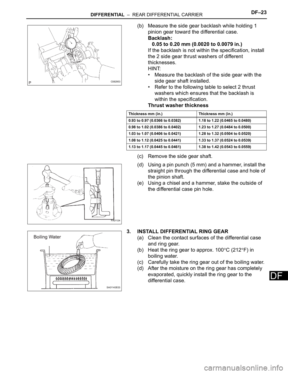
(b) Measure the side gear backlash while holding 1
pinion gear toward the differential case.
Backlash:
0.05 to 0.20 mm (0.0020 to 0.0079 in.)
If the backlash is not within the specification, install
the 2 side gear thrust washers of different
thicknesses.
HINT:
• Measure the backlash of the side gear with the
side gear shaft installed.
• Refer to the following table to select 2 thrust
washers which ensures that the backlash is
within the specification.
Thrust washer thickness
(c) Remove the side gear shaft.
(d) Using a pin punch (5 mm) and a hammer, install the
straight pin through the differential case and hole of
the pinion shaft.
(e) Using a chisel and a hammer, stake the outside of
the differential case pin hole.
3. INSTALL DIFFERENTIAL RING GEAR
(a) Clean the contact surfaces of the differential case
and ring gear.
(b) Heat the ring gear to approx. 100
C (212F) in
boiling water.
(c) Carefully take the ring gear out of the boiling water.
(d) After the moisture on the ring gear has completely
evaporated, quickly install the ring gear to the
differential case.
C082953
Thickness mm (in.) Thickness mm (in.)
0.93 to 0.97 (0.0366 to 0.0382) 1.18 to 1.22 (0.0465 to 0.0480)
0.98 to 1.02 (0.0386 to 0.0402) 1.23 to 1.27 (0.0484 to 0.0500)
1.03 to 1.07 (0.0406 to 0.0421) 1.28 to 1.32 (0.0504 to 0.0520)
1.08 to 1.12 (0.0425 to 0.0441) 1.33 to 1.37 (0.0524 to 0.0539)
1.13 to 1.17 (0.0445 to 0.0461) 1.38 to 1.42 (0.0543 to 0.0559)
FA01124
SA01143E03
Page 2672 of 3000
SR–8STEERING COLUMN – STEERING COLUMN ASSEMBLY
SR
DISASSEMBLY
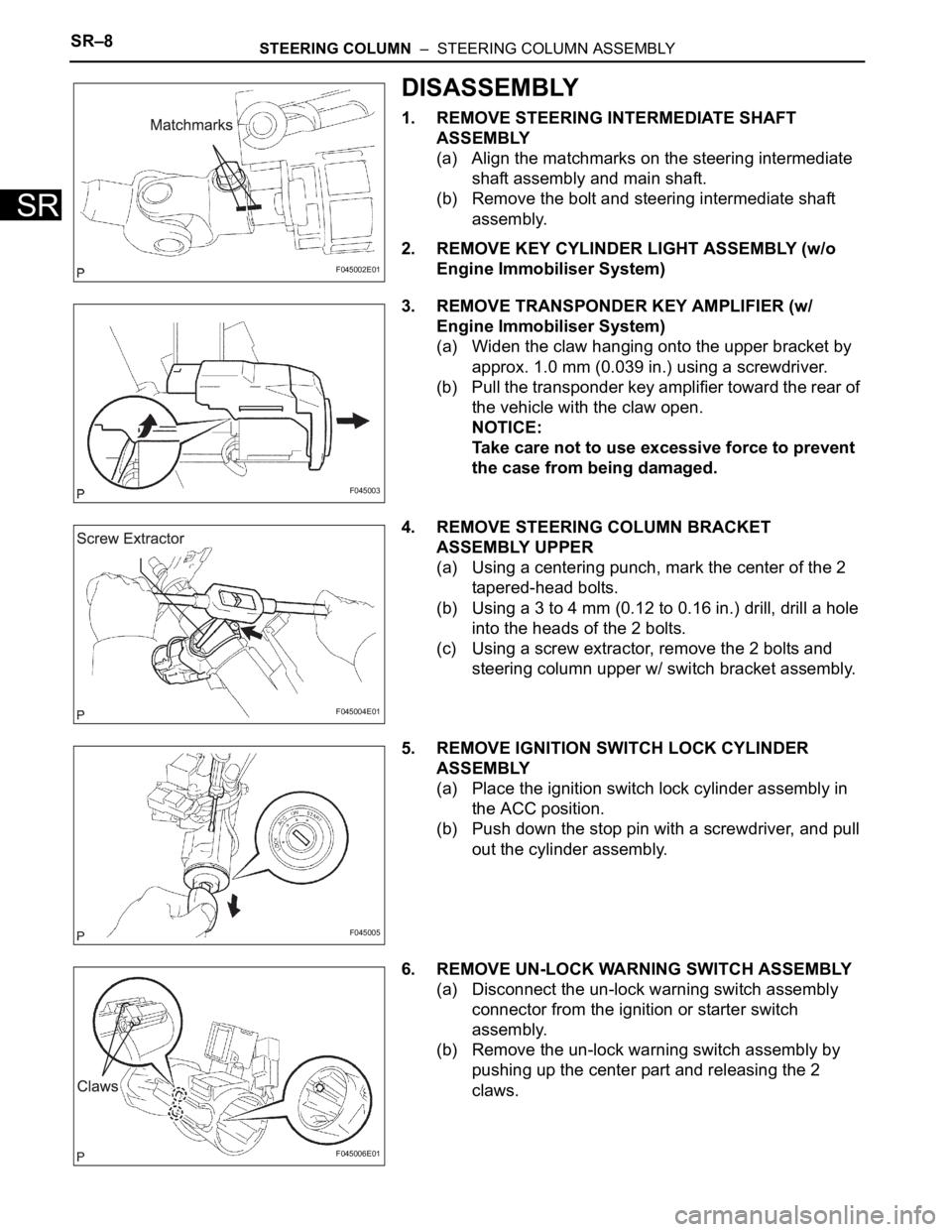
1. REMOVE STEERING INTERMEDIATE SHAFT
ASSEMBLY
(a) Align the matchmarks on the steering intermediate
shaft assembly and main shaft.
(b) Remove the bolt and steering intermediate shaft
assembly.
2. REMOVE KEY CYLINDER LIGHT ASSEMBLY (w/o
Engine Immobiliser System)
3. REMOVE TRANSPONDER KEY AMPLIFIER (w/
Engine Immobiliser System)
(a) Widen the claw hanging onto the upper bracket by
approx. 1.0 mm (0.039 in.) using a screwdriver.
(b) Pull the transponder key amplifier toward the rear of
the vehicle with the claw open.
NOTICE:
Take care not to use excessive force to prevent
the case from being damaged.
4. REMOVE STEERING COLUMN BRACKET
ASSEMBLY UPPER
(a) Using a centering punch, mark the center of the 2
tapered-head bolts.
(b) Using a 3 to 4 mm (0.12 to 0.16 in.) drill, drill a hole
into the heads of the 2 bolts.
(c) Using a screw extractor, remove the 2 bolts and
steering column upper w/ switch bracket assembly.
5. REMOVE IGNITION SWITCH LOCK CYLINDER
ASSEMBLY
(a) Place the ignition switch lock cylinder assembly in
the ACC position.
(b) Push down the stop pin with a screwdriver, and pull
out the cylinder assembly.
6. REMOVE UN-LOCK WARNING SWITCH ASSEMBLY
(a) Disconnect the un-lock warning switch assembly
connector from the ignition or starter switch
assembly.
(b) Remove the un-lock warning switch assembly by
pushing up the center part and releasing the 2
claws.
F045002E01
F045003
F045004E01
F045005
F045006E01