2007 TOYOTA SIENNA tow
[x] Cancel search: towPage 51 of 3000

INTRODUCTION – HOW TO TROUBLESHOOT ECU CONTROLLED SYSTEMSIN–39
IN
• In the DTC check, it is very important to determine
whether the problem indicated by the DTC either: 1)
still occurs, or 2) occurred in the past but has returned
to normal. In addition, the DTC should be compared
to the problem symptom to see if they are related. For
this reason, DTCs should be checked before and after
confirmation of symptoms (i.e., whether or not
problem symptoms exist) to determine current system
conditions, as shown in the flowchart below.
• Never skip the DTC check. Failing to check DTCs
may, depending on the case, result in unnecessary
troubleshooting for systems operating normally or
lead to repairs not related to the problem. Follow the
procedures listed in the flowchart in the correct order.
Theft Deterrent System XXXXX
Engine Immobiliser System
XX
Cruise Control SystemXXX
Dynamic Laser Cruise Control System
XXX
Lighting System
XX
Wiper and Washer SystemXXXXX
Power Door Lock Control System X X X
Wireless Door Lock Control SystemXX
Key Reminder Warning System X X XX
Meter / Gauge System X X X
Audio and Visual SystemXXXX
Rear Seat Entertainment System XXXXX
Navigation System
XXXX
Clearance Sonar SystemXXXXX
Rear View Monitor System XXXXX
Power Window Control System (with Jam
Protection Function)XXX
Power Window Control System (without Jam
Protection Function)XXXXX
Power Mirror Control System (with Memory) X X X
Power Mirror Control System (without Memory)XXXXX
Front Power Seat Control System X X X
Rear No. 2 Seat Assembly (with Power Stowing
Function)XXXXX
Window Deogger SystemXXXXX
Power Slide Door System
XX
Slide Door Closer System X X X
Back Door Closer SystemXX
Power Back Door SystemXX
Sliding Roof System XXXXX
Multiplex Communication System XXXXX
CAN Communication System XXXXXSystemSYMPTOM CONFIRMATION AND DIAGNOSTIC TROUBLE CODE
DTC Check
(Normal Mode)DTC Check
(Check Mode)Sensor Check/
Test Mode
(Input Signal
Check)Data List Active Test
Page 69 of 3000

INTRODUCTION – HOW TO TROUBLESHOOT ECU CONTROLLED SYSTEMSIN–39
IN
• In the DTC check, it is very important to determine
whether the problem indicated by the DTC either: 1)
still occurs, or 2) occurred in the past but has returned
to normal. In addition, the DTC should be compared
to the problem symptom to see if they are related. For
this reason, DTCs should be checked before and after
confirmation of symptoms (i.e., whether or not
problem symptoms exist) to determine current system
conditions, as shown in the flowchart below.
• Never skip the DTC check. Failing to check DTCs
may, depending on the case, result in unnecessary
troubleshooting for systems operating normally or
lead to repairs not related to the problem. Follow the
procedures listed in the flowchart in the correct order.
Theft Deterrent System XXXXX
Engine Immobiliser System
XX
Cruise Control SystemXXX
Dynamic Laser Cruise Control System
XXX
Lighting System
XX
Wiper and Washer SystemXXXXX
Power Door Lock Control System X X X
Wireless Door Lock Control SystemXX
Key Reminder Warning System X X XX
Meter / Gauge System X X X
Audio and Visual SystemXXXX
Rear Seat Entertainment System XXXXX
Navigation System
XXXX
Clearance Sonar SystemXXXXX
Rear View Monitor System XXXXX
Power Window Control System (with Jam
Protection Function)XXX
Power Window Control System (without Jam
Protection Function)XXXXX
Power Mirror Control System (with Memory) X X X
Power Mirror Control System (without Memory)XXXXX
Front Power Seat Control System X X X
Rear No. 2 Seat Assembly (with Power Stowing
Function)XXXXX
Window Deogger SystemXXXXX
Power Slide Door System
XX
Slide Door Closer System X X X
Back Door Closer SystemXX
Power Back Door SystemXX
Sliding Roof System XXXXX
Multiplex Communication System XXXXX
CAN Communication System XXXXXSystemSYMPTOM CONFIRMATION AND DIAGNOSTIC TROUBLE CODE
DTC Check
(Normal Mode)DTC Check
(Check Mode)Sensor Check/
Test Mode
(Input Signal
Check)Data List Active Test
Page 119 of 3000
DS–14DRIVE SHAFT – FRONT DRIVE SHAFT
DS
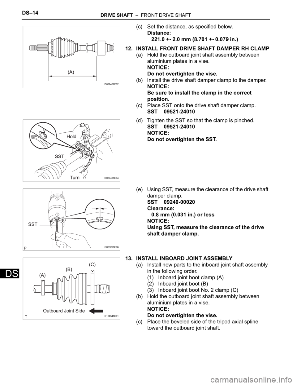
(c) Set the distance, as specified below.
Distance:
221.0 +- 2.0 mm (8.701 +- 0.079 in.)
12. INSTALL FRONT DRIVE SHAFT DAMPER RH CLAMP
(a) Hold the outboard joint shaft assembly between
aluminium plates in a vise.
NOTICE:
Do not overtighten the vise.
(b) Install the drive shaft damper clamp to the damper.
NOTICE:
Be sure to install the clamp in the correct
position.
(c) Place SST onto the drive shaft damper clamp.
SST 09521-24010
(d) Tighten the SST so that the clamp is pinched.
SST 09521-24010
NOTICE:
Do not overtighten the SST.
(e) Using SST, measure the clearance of the drive shaft
damper clamp.
SST 09240-00020
Clearance:
0.8 mm (0.031 in.) or less
NOTICE:
Using SST, measure the clearance of the drive
shaft damper clamp.
13. INSTALL INBOARD JOINT ASSEMBLY
(a) Install new parts to the inboard joint shaft assembly
in the following order.
(1) Inboard joint boot clamp (A)
(2) Inboard joint boot (B)
(3) Inboard joint boot No. 2 clamp (C)
(b) Hold the outboard joint shaft assembly between
aluminium plates in a vise.
NOTICE:
Do not overtighten the vise.
(c) Place the beveled side of the tripod axial spline
toward the outboard joint shaft.
D027407E02
D027408E04
C086268E06
C104548E01
Page 293 of 3000
INSTRUMENT PANEL – INSTRUMENT PANEL SAFETY PADIP–9
IP
30. REMOVE FLOOR SHIFT POSITION INDICATOR
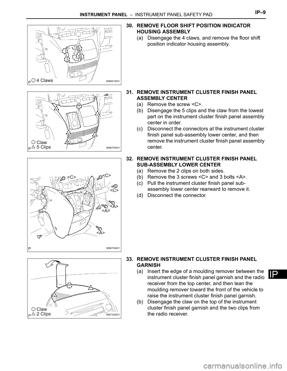
HOUSING ASSEMBLY
(a) Disengage the 4 claws, and remove the floor shift
position indicator housing assembly.
31. REMOVE INSTRUMENT CLUSTER FINISH PANEL
ASSEMBLY CENTER
(a) Remove the screw
(b) Disengage the 5 clips and the claw from the lowest
part on the instrument cluster finish panel assembly
center in order.
(c) Disconnect the connectors at the instrument cluster
finish panel sub-assembly lower center, and then
remove the instrument cluster finish panel assembly
center.
32. REMOVE INSTRUMENT CLUSTER FINISH PANEL
SUB-ASSEMBLY LOWER CENTER
(a) Remove the 2 clips on both sides.
(b) Remove the 3 screws
(c) Pull the instrument cluster finish panel sub-
assembly lower center rearward to remove it.
(d) Disconnect the connector.
33. REMOVE INSTRUMENT CLUSTER FINISH PANEL
GARNISH
(a) Insert the edge of a moulding remover between the
instrument cluster finish panel garnish and the radio
receiver from the top center, and then lean the
moulding remover toward the front of the vehicle to
raise the instrument cluster finish panel garnish.
(b) Disengage the claw on the top of the instrument
cluster finish panel garnish and the two clips from
the radio receiver.
B068514E01
B066703E01
B066704E01
B067325E01
Page 412 of 3000
ES–1062GR-FE ENGINE CONTROL SYSTEM – SFI SYSTEM
ES
DESCRIPTION
Refer to DTC P0335 (See page ES-220).
MONITOR DESCRIPTION
DTC P0016 and P0018
The ECM optimizes the valve timing by using the VVT (Variable Valve Timing) system to control the intake
camshaft. The VVT system includes the ECM, the Oil Control Valve (OCV) and the VVT controller.
The ECM sends a target duty-cycle control signal to the OCV. This control signal regulates the oil
pressure applied to the VVT controller. The VVT controller can advance or retard the intake camshaft. The
ECM calibrates the intake valve timing by setting the intake camshaft to the most retarded angle while the
engine is idling. The ECM closes the OCV to retard the cam. The ECM stores this value as the VVT
learning value. When the difference between the target and actual intake valve timings is 5
CA
(Crankshaft Angle) or less, the ECM stores it.
If the VVT learning value matches the following conditions, the ECM determines the existence of a
malfunction in the VVT system, and sets the DTC.
• The VVT learning value: Less than 18.5
CA, or more than 43.5 CA.
• The above condition continues for 18 seconds or more.
This DTC indicates that the intake camshaft has been installed toward the crankshaft at an incorrect
angle, caused by factors such as the timing chain having jumped a tooth.
This monitor begins to run after the engine has idled for 5 minutes.
DTC P0017 and P0019
The ECM checks valve timing (VVT learning value) on the exhaust side while the engine is running at a
low speed, in order to monitor the gap between current and target valve timings on the exhaust side. The
VVT learning value is calculated from the positions of the camshaft and crankshaft. The camshaft will
come to the most retarded position when the engine is running at a low speed. If the camshaft position is
normal, the VVT learning value should be within the specified range. If the VVT learning value is not within
the specified range, the ECM determines this as a malfunction.
DTC P0016Crankshaft Position - Camshaft Position Corre-
lation (Bank 1 Sensor A)
DTC P0017Crankshaft Position - Camshaft Position Corre-
lation (Bank 1 Sensor B)
DTC P0018Crankshaft Position - Camshaft Position Corre-
lation (Bank 2 Sensor A)
DTC P0019Crankshaft Position - Camshaft Position Corre-
lation (Bank 2 Sensor B)
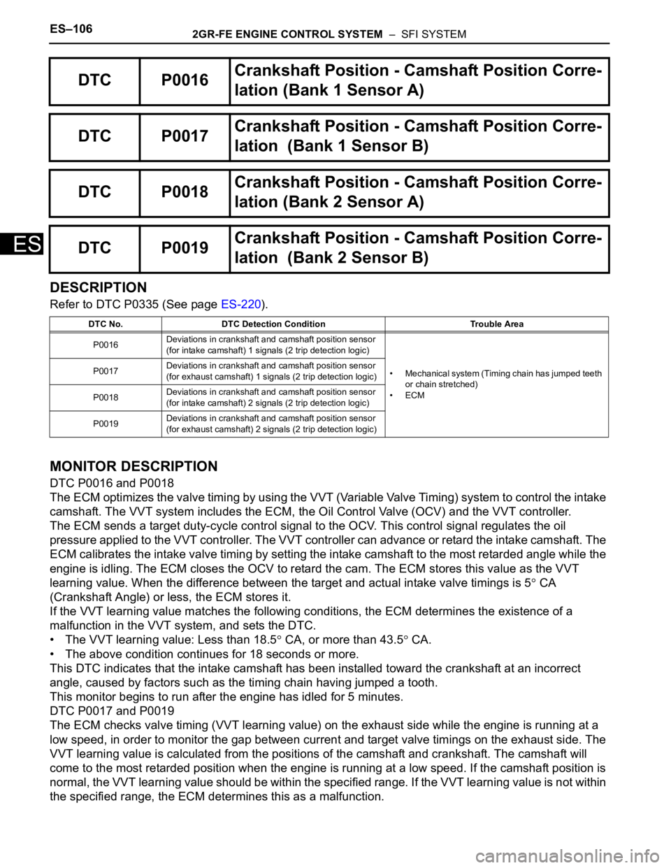
DTC No. DTC Detection Condition Trouble Area
P0016Deviations in crankshaft and camshaft position sensor
(for intake camshaft) 1 signals (2 trip detection logic)
• Mechanical system (Timing chain has jumped teeth
or chain stretched)
•ECM P0017Deviations in crankshaft and camshaft position sensor
(for exhaust camshaft) 1 signals (2 trip detection logic)
P0018Deviations in crankshaft and camshaft position sensor
(for intake camshaft) 2 signals (2 trip detection logic)
P0019Deviations in crankshaft and camshaft position sensor
(for exhaust camshaft) 2 signals (2 trip detection logic)
Page 841 of 3000
ET–4EXTERIOR – FRONT BUMPER
ET
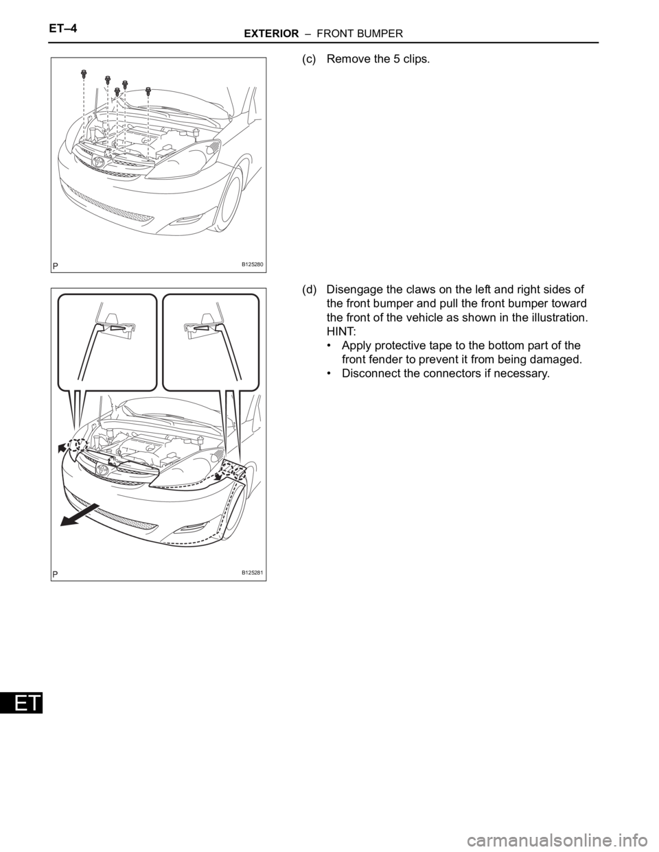
(c) Remove the 5 clips.
(d) Disengage the claws on the left and right sides of
the front bumper and pull the front bumper toward
the front of the vehicle as shown in the illustration.
HINT:
• Apply protective tape to the bottom part of the
front fender to prevent it from being damaged.
• Disconnect the connectors if necessary.
B125280
B125281
Page 1961 of 3000
AX–276U151F AUTOMATIC TRANSAXLE – DIFFERENTIAL CASE
AX
INSPECTION
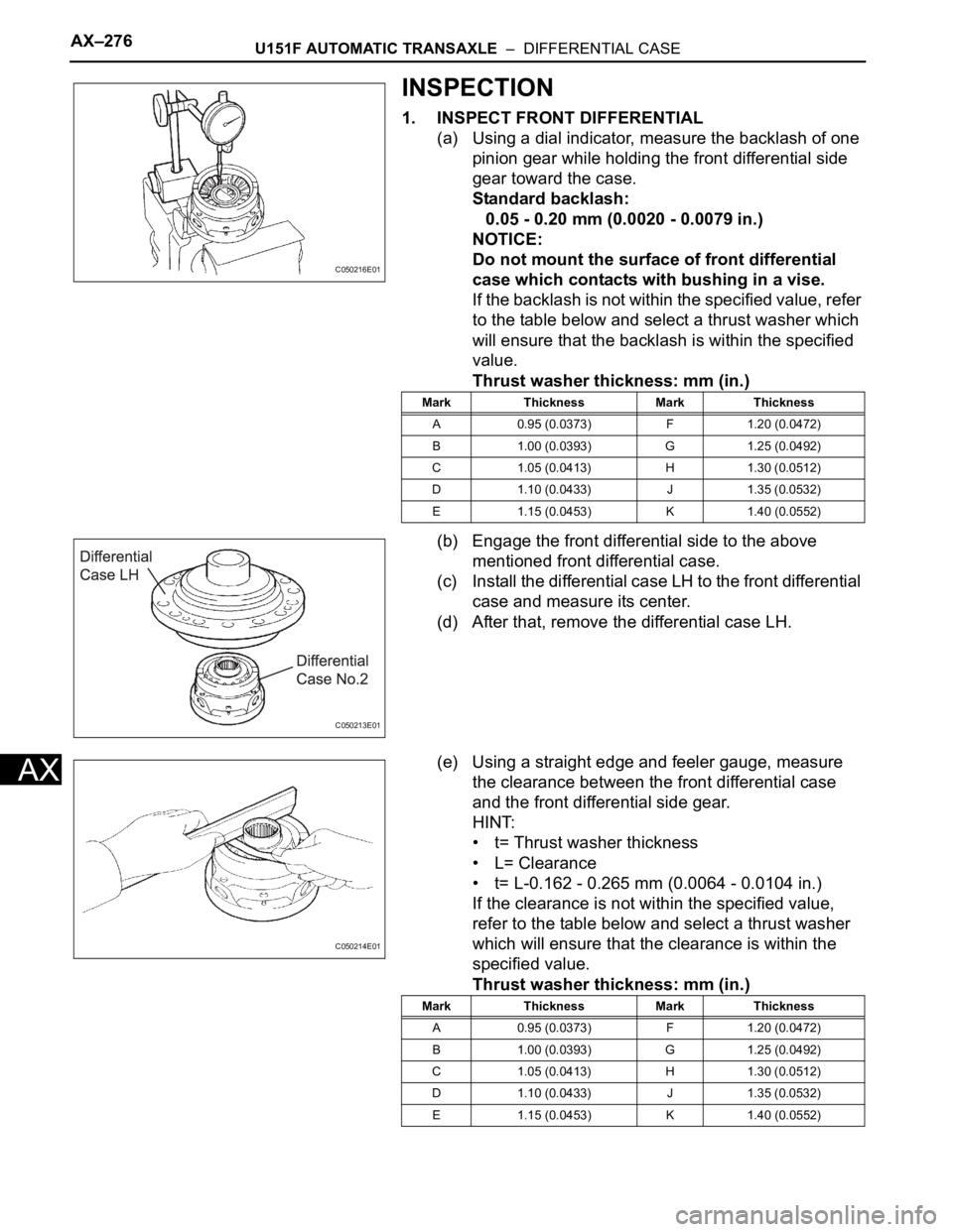
1. INSPECT FRONT DIFFERENTIAL
(a) Using a dial indicator, measure the backlash of one
pinion gear while holding the front differential side
gear toward the case.
Standard backlash:
0.05 - 0.20 mm (0.0020 - 0.0079 in.)
NOTICE:
Do not mount the surface of front differential
case which contacts with bushing in a vise.
If the backlash is not within the specified value, refer
to the table below and select a thrust washer which
will ensure that the backlash is within the specified
value.
Thrust washer thickness: mm (in.)
(b) Engage the front differential side to the above
mentioned front differential case.
(c) Install the differential case LH to the front differential
case and measure its center.
(d) After that, remove the differential case LH.
(e) Using a straight edge and feeler gauge, measure
the clearance between the front differential case
and the front differential side gear.
HINT:
• t= Thrust washer thickness
• L= Clearance
• t= L-0.162 - 0.265 mm (0.0064 - 0.0104 in.)
If the clearance is not within the specified value,
refer to the table below and select a thrust washer
which will ensure that the clearance is within the
specified value.
Thrust washer thickness: mm (in.)
C050216E01
Mark Thickness Mark Thickness
A 0.95 (0.0373) F 1.20 (0.0472)
B 1.00 (0.0393) G 1.25 (0.0492)
C 1.05 (0.0413) H 1.30 (0.0512)
D 1.10 (0.0433) J 1.35 (0.0532)
E 1.15 (0.0453) K 1.40 (0.0552)
C050213E01
C050214E01
Mark Thickness Mark Thickness
A 0.95 (0.0373) F 1.20 (0.0472)
B 1.00 (0.0393) G 1.25 (0.0492)
C 1.05 (0.0413) H 1.30 (0.0512)
D 1.10 (0.0433) J 1.35 (0.0532)
E 1.15 (0.0453) K 1.40 (0.0552)
Page 1962 of 3000
U151F AUTOMATIC TRANSAXLE – DIFFERENTIAL CASEAX–277
AX
If the clearance is not within the specified value,
parts may have been assembled incorrectly, so
check and reassemble it.
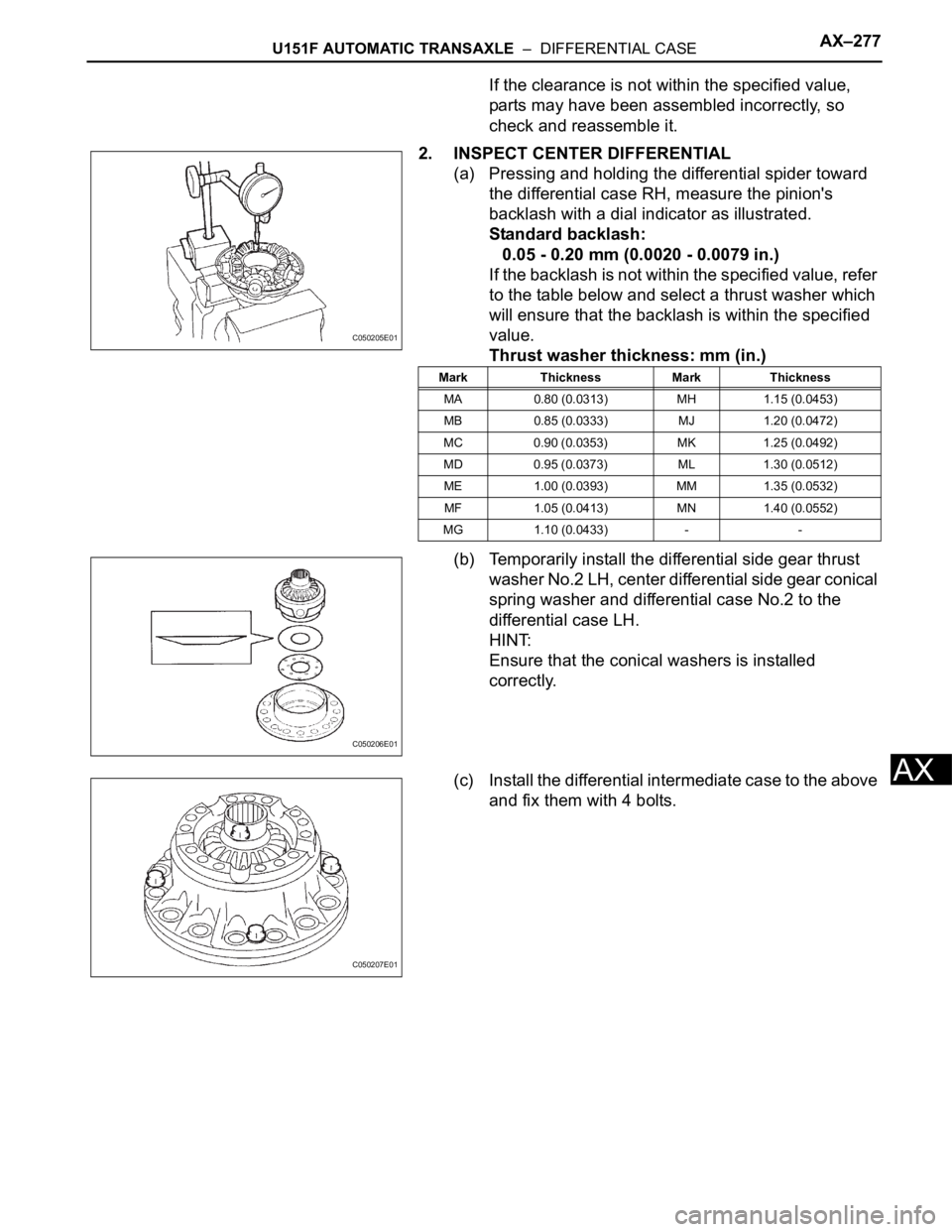
2. INSPECT CENTER DIFFERENTIAL
(a) Pressing and holding the differential spider toward
the differential case RH, measure the pinion's
backlash with a dial indicator as illustrated.
Standard backlash:
0.05 - 0.20 mm (0.0020 - 0.0079 in.)
If the backlash is not within the specified value, refer
to the table below and select a thrust washer which
will ensure that the backlash is within the specified
value.
Thrust washer thickness: mm (in.)
(b) Temporarily install the differential side gear thrust
washer No.2 LH, center differential side gear conical
spring washer and differential case No.2 to the
differential case LH.
HINT:
Ensure that the conical washers is installed
correctly.
(c) Install the differential intermediate case to the above
and fix them with 4 bolts.
C050205E01
Mark Thickness Mark Thickness
MA 0.80 (0.0313) MH 1.15 (0.0453)
MB 0.85 (0.0333) MJ 1.20 (0.0472)
MC 0.90 (0.0353) MK 1.25 (0.0492)
MD 0.95 (0.0373) ML 1.30 (0.0512)
ME 1.00 (0.0393) MM 1.35 (0.0532)
MF 1.05 (0.0413) MN 1.40 (0.0552)
MG 1.10 (0.0433) - -
C050206E01
C050207E01