Page 105 of 3000
AX–170U151F AUTOMATIC TRANSAXLE – AUTOMATIC TRANSAXLE ASSEMBLY
AX
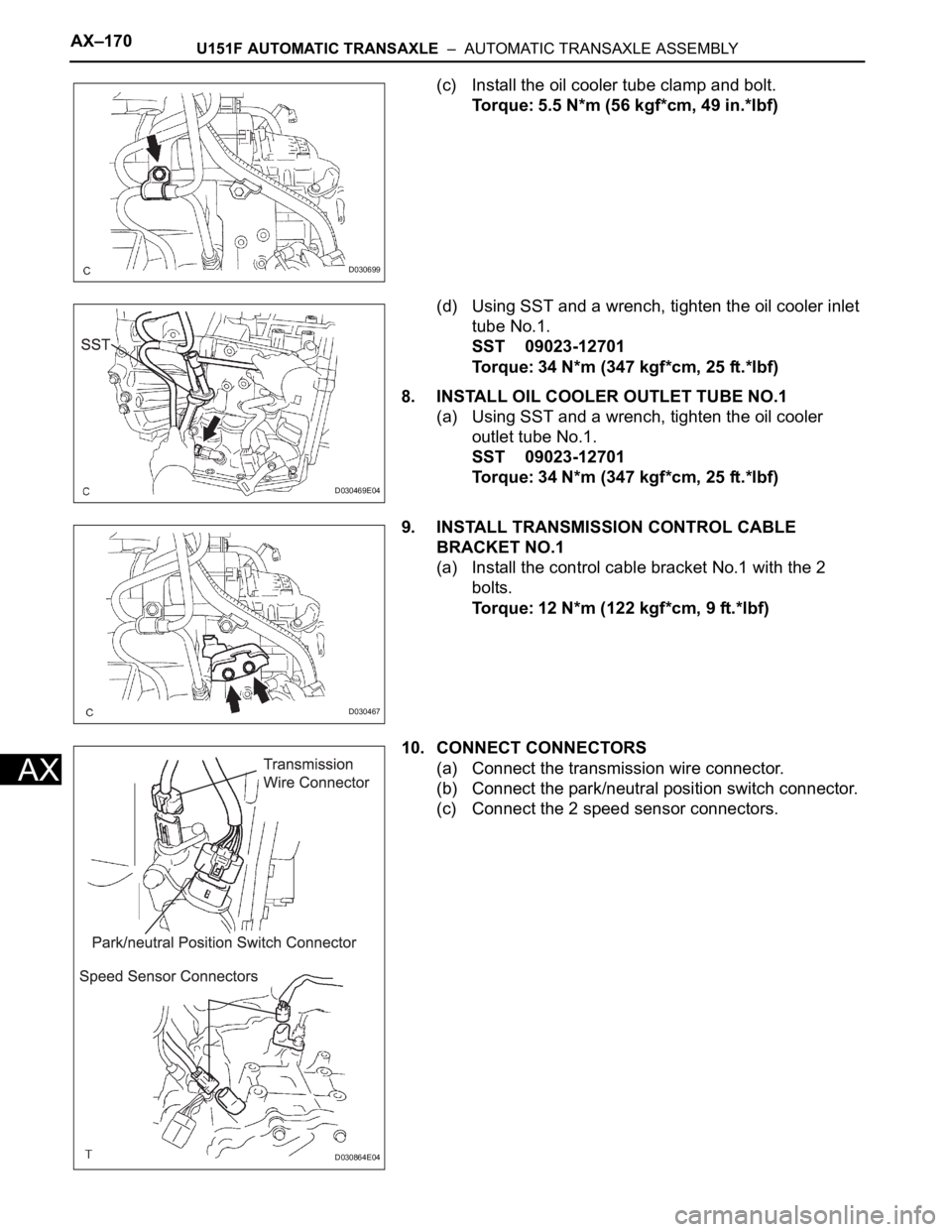
(c) Install the oil cooler tube clamp and bolt.
Torque: 5.5 N*m (56 kgf*cm, 49 in.*lbf)
(d) Using SST and a wrench, tighten the oil cooler inlet
tube No.1.
SST 09023-12701
Torque: 34 N*m (347 kgf*cm, 25 ft.*lbf)
8. INSTALL OIL COOLER OUTLET TUBE NO.1
(a) Using SST and a wrench, tighten the oil cooler
outlet tube No.1.
SST 09023-12701
Torque: 34 N*m (347 kgf*cm, 25 ft.*lbf)
9. INSTALL TRANSMISSION CONTROL CABLE
BRACKET NO.1
(a) Install the control cable bracket No.1 with the 2
bolts.
Torque: 12 N*m (122 kgf*cm, 9 ft.*lbf)
10. CONNECT CONNECTORS
(a) Connect the transmission wire connector.
(b) Connect the park/neutral position switch connector.
(c) Connect the 2 speed sensor connectors.
D030699
D030469E04
D030467
D030864E04
Page 106 of 3000
U151F AUTOMATIC TRANSAXLE – AUTOMATIC TRANSAXLE ASSEMBLYAX–171
AX
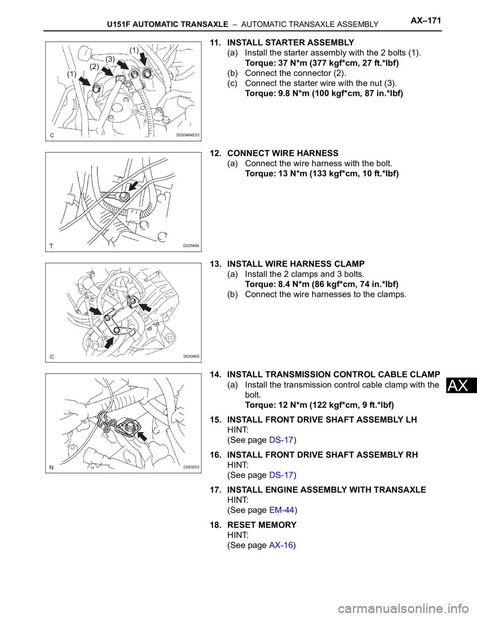
11. INSTALL STARTER ASSEMBLY
(a) Install the starter assembly with the 2 bolts (1).
Torque: 37 N*m (377 kgf*cm, 27 ft.*lbf)
(b) Connect the connector (2).
(c) Connect the starter wire with the nut (3).
Torque: 9.8 N*m (100 kgf*cm, 87 in.*lbf)
12. CONNECT WIRE HARNESS
(a) Connect the wire harness with the bolt.
Torque: 13 N*m (133 kgf*cm, 10 ft.*lbf)
13. INSTALL WIRE HARNESS CLAMP
(a) Install the 2 clamps and 3 bolts.
Torque: 8.4 N*m (86 kgf*cm, 74 in.*lbf)
(b) Connect the wire harnesses to the clamps.
14. INSTALL TRANSMISSION CONTROL CABLE CLAMP
(a) Install the transmission control cable clamp with the
bolt.
Torque: 12 N*m (122 kgf*cm, 9 ft.*lbf)
15. INSTALL FRONT DRIVE SHAFT ASSEMBLY LH
HINT:
(See page DS-17)
16. INSTALL FRONT DRIVE SHAFT ASSEMBLY RH
HINT:
(See page DS-17)
17. INSTALL ENGINE ASSEMBLY WITH TRANSAXLE
HINT:
(See page EM-44)
18. RESET MEMORY
HINT:
(See page AX-16)
D030464E03
G025456
D030465
C083203
Page 107 of 3000
TRANSFER – TRANSFER ASSEMBLYTF–9
TF
INSTALLATION
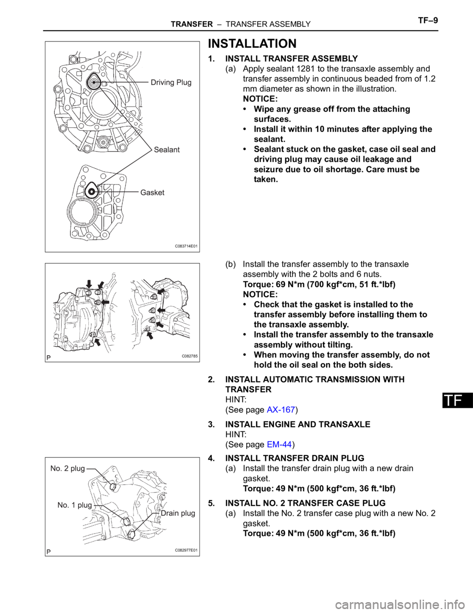
1. INSTALL TRANSFER ASSEMBLY
(a) Apply sealant 1281 to the transaxle assembly and
transfer assembly in continuous beaded from of 1.2
mm diameter as shown in the illustration.
NOTICE:
• Wipe any grease off from the attaching
surfaces.
• Install it within 10 minutes after applying the
sealant.
• Sealant stuck on the gasket, case oil seal and
driving plug may cause oil leakage and
seizure due to oil shortage. Care must be
taken.
(b) Install the transfer assembly to the transaxle
assembly with the 2 bolts and 6 nuts.
Torque: 69 N*m (700 kgf*cm, 51 ft.*lbf)
NOTICE:
• Check that the gasket is installed to the
transfer assembly before installing them to
the transaxle assembly.
• Install the transfer assembly to the transaxle
assembly without tilting.
• When moving the transfer assembly, do not
hold the oil seal on the both sides.
2. INSTALL AUTOMATIC TRANSMISSION WITH
TRANSFER
HINT:
(See page AX-167)
3. INSTALL ENGINE AND TRANSAXLE
HINT:
(See page EM-44)
4. INSTALL TRANSFER DRAIN PLUG
(a) Install the transfer drain plug with a new drain
gasket.
Torque: 49 N*m (500 kgf*cm, 36 ft.*lbf)
5. INSTALL NO. 2 TRANSFER CASE PLUG
(a) Install the No. 2 transfer case plug with a new No. 2
gasket.
Torque: 49 N*m (500 kgf*cm, 36 ft.*lbf)
C083714E01
C082785
C082977E01
Page 108 of 3000
TF–10TRANSFER – TRANSFER ASSEMBLY
TF
6. INSTALL NO. 1 TRANSFER CASE PLUG
(a) Add oil up to 0 to 5 mm below the lower side of the
plug hole.
Oil quantity:
0.9 L (0.95 US qts, 0.71 lmp. qts)
HINT:
When adding oil, pour it slowly.
(b) Install the No. 1 transfer case plug with a new No. 1
gasket.
Torque: 49 N*m (500 kgf*cm, 36 ft.*lbf)
7. INSPECT AND ADJUST FRONT WHEEL ALIGNMENT
HINT:
(See page SP-4)
8. CHECK ABS SPEED SENSOR SIGNAL
HINT:
(See page BC-3)
Page 110 of 3000
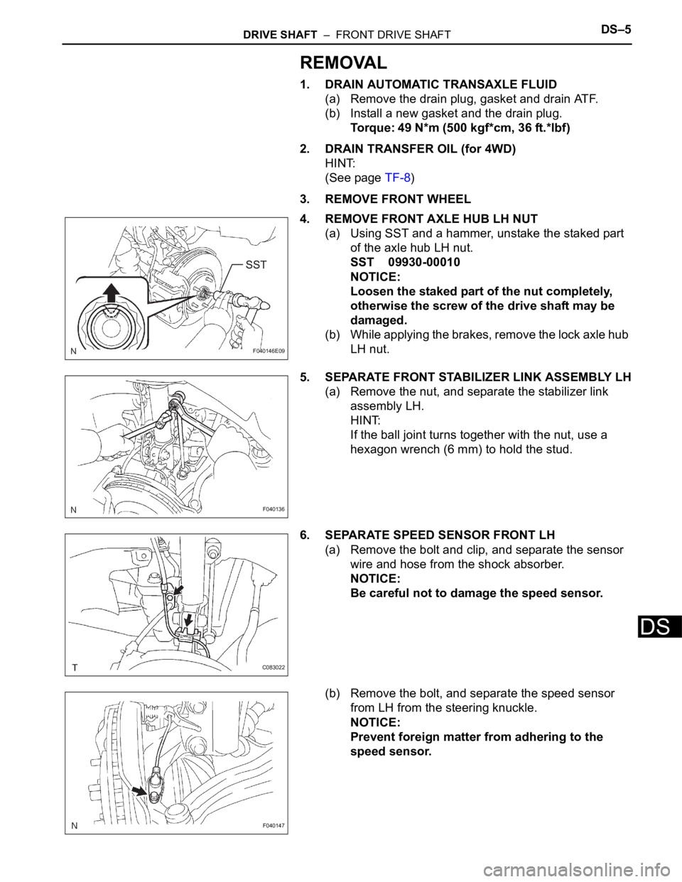
DRIVE SHAFT – FRONT DRIVE SHAFTDS–5
DS
REMOVAL
1. DRAIN AUTOMATIC TRANSAXLE FLUID
(a) Remove the drain plug, gasket and drain ATF.
(b) Install a new gasket and the drain plug.
Torque: 49 N*m (500 kgf*cm, 36 ft.*lbf)
2. DRAIN TRANSFER OIL (for 4WD)
HINT:
(See page TF-8)
3. REMOVE FRONT WHEEL
4. REMOVE FRONT AXLE HUB LH NUT
(a) Using SST and a hammer, unstake the staked part
of the axle hub LH nut.
SST 09930-00010
NOTICE:
Loosen the staked part of the nut completely,
otherwise the screw of the drive shaft may be
damaged.
(b) While applying the brakes, remove the lock axle hub
LH nut.
5. SEPARATE FRONT STABILIZER LINK ASSEMBLY LH
(a) Remove the nut, and separate the stabilizer link
assembly LH.
HINT:
If the ball joint turns together with the nut, use a
hexagon wrench (6 mm) to hold the stud.
6. SEPARATE SPEED SENSOR FRONT LH
(a) Remove the bolt and clip, and separate the sensor
wire and hose from the shock absorber.
NOTICE:
Be careful not to damage the speed sensor.
(b) Remove the bolt, and separate the speed sensor
from LH from the steering knuckle.
NOTICE:
Prevent foreign matter from adhering to the
speed sensor.
F040146E09
F040136
C083022
F040147
Page 125 of 3000
PREPARATION – 2GR-FE EMISSION CONTROLPP–11
PP
EQUIPMENT
vacuum pump
Ohmmeter
Service Wire Harness
Torque wrench
Pressure gauge
Vernier calipers
Page 134 of 3000
PREPARATION – U151E AUTOMATIC TRANSAXLEPP–27
PP
EQUIPMENT
Straight edge
Torque wrench
Vernier calipers
Dial indicator with magnetic base
Slide calipers
Chain block
Feeler gauge
Plastic hammer
Press
Seal packing 2403, THREE BOND 2403 or equivalent
Seal packing 2430, THREE BOND 2430 or equivalent
Page 139 of 3000
PREPARATION – U151F AUTOMATIC TRANSAXLEPP–35
PP
EQUIPMENT
Straight edge
Torque wrench
Vernier calipers
Dial indicator with magnetic base
Slide calipers
Chain block
Feeler gauge
Plastic hammer
Press
Seal packing 2403, THREE BOND 2403 or equivalent
Seal packing 2430, THREE BOND 2430 or equivalent