2006 MERCEDES-BENZ SPRINTER ignition
[x] Cancel search: ignitionPage 2005 of 2305
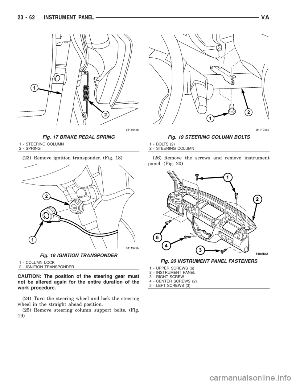
(23) Remove ignition transponder. (Fig. 18)
CAUTION: The position of the steering gear must
not be altered again for the entire duration of the
work procedure.
(24) Turn the steering wheel and lock the steering
wheel in the straight ahead position.
(25) Remove steering column support bolts. (Fig.
19)(26) Remove the screws and remove instrument
panel. (Fig. 20)
Fig. 17 BRAKE PEDAL SPRING
1 - STEERING COLUMN
2 - SPRING
Fig. 18 IGNITION TRANSPONDER
1 - COLUMN LOCK
2 - IGNITION TRANSPONDER
Fig. 19 STEERING COLUMN BOLTS
1 - BOLTS (2)
2 - STEERING COLUMN
Fig. 20 INSTRUMENT PANEL FASTENERS
1 - UPPER SCREWS (6)
2 - INSTRUMENT PANEL
3 - RIGHT SCREW
4 - CENTER SCREWS (2)
5 - LEFT SCREWS (3)
23 - 62 INSTRUMENT PANELVA
Page 2006 of 2305
INSTALLATION
WARNING: ON VEHICLES EQUIPPED WITH AIR-
BAGS, DISABLE THE AIRBAG SYSTEM BEFORE
ATTEMPTING ANY STEERING WHEEL, STEERING
COLUMN, SEAT BELT TENSIONER, OR INSTRU-
MENT PANEL COMPONENT DIAGNOSIS OR SER-
VICE. DISCONNECT AND ISOLATE THE BATTERY
NEGATIVE (GROUND) CABLE, THEN WAIT TWO
MINUTES FOR THE AIRBAG SYSTEM CAPACITOR
TO DISCHARGE BEFORE PERFORMING FURTHER
DIAGNOSIS OR SERVICE. THIS IS THE ONLY SURE
WAY TO DISABLE THE AIRBAG SYSTEM. FAILURE
TO TAKE THE PROPER PRECAUTIONS COULD
RESULT IN ACCIDENTAL AIRBAG DEPLOYMENT
AND POSSIBLE PERSONAL INJURY.
²WHEN REMOVING A DEPLOYED AIRBAG, RUB-
BER GLOVES, EYE PROTECTION, AND A LONG-
SLEEVED SHIRT SHOULD BE WORN. THERE MAY
BE DEPOSITS ON THE AIRBAG UNIT AND OTHER
INTERIOR SURFACES. IN LARGE DOSES, THESE
DEPOSITS MAY CAUSE IRRITATION TO THE SKIN
AND EYES.
²USE EXTREME CARE TO PREVENT ANY FOR-
EIGN MATERIAL FROM ENTERING THE PASSEN-
GER AIRBAG, OR BECOMING ENTRAPPED
BETWEEN THE PASSENGER AIRBAG CUSHION
AND THE PASSENGER AIRBAG DOOR. FAILURE TO
OBSERVE THIS WARNING COULD RESULT IN
OCCUPANT INJURIES UPON AIRBAG DEPLOY-
MENT.
²THE PASSENGER AIRBAG DOOR MUST
NEVER BE PAINTED. REPLACEMENT PASSENGER
AIRBAGS ARE SERVICED WITH DOORS IN THE
ORIGINAL COLORS. PAINT MAY CHANGE THE WAY
IN WHICH THE MATERIAL OF THE AIRBAG DOOR
RESPONDS TO AN AIRBAG DEPLOYMENT. FAIL-
URE TO OBSERVE THIS WARNING COULD RESULT
IN OCCUPANT INJURIES UPON AIRBAG DEPLOY-
MENT.
(1) Install the instrument panel.
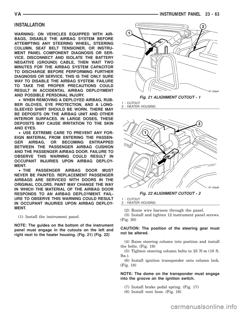
NOTE: The guides on the bottom of the instrument
panel must engage in the cutouts on the left and
right next to the heater housing. (Fig. 21) (Fig. 22)(2) Route wire harness through the panel.
(3) Install and tighten 12 instrument panel screws.
(Fig. 20)
CAUTION: The position of the steering gear must
not be altered.
(4) Raise steering column into position and install
the bolts. (Fig. 19)
(5) Tighten steering column bolts to 25 N´m (18 ft.
lbs.).
(6) Install ignition transponder onto column lock.
(Fig. 18)
NOTE: The dome on the transponder must engage
into the groove on the ignition switch.
(7) Install brake pedal spring. (Fig. 17)
(8) Install vent hose. (Fig. 16)
Fig. 21 ALIGNMENT CUTOUT - 1
1 - CUTOUT
2 - HEATER HOUSING
Fig. 22 ALIGNMENT CUTOUT - 2
1 - CUTOUT
2 - HEATER HOUSING
VAINSTRUMENT PANEL 23 - 63
Page 2056 of 2305
BLOWER MOTOR SWITCH
DESCRIPTION
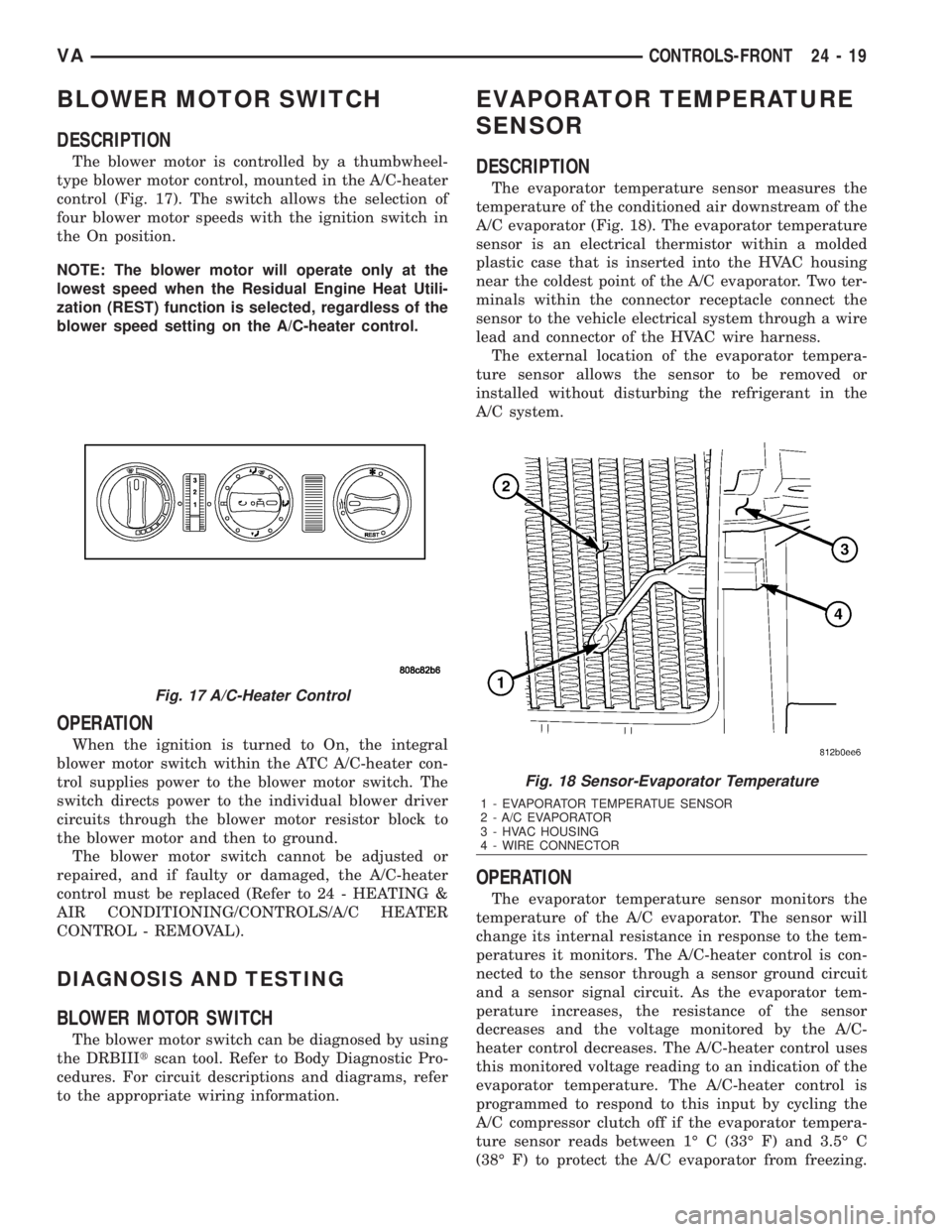
The blower motor is controlled by a thumbwheel-
type blower motor control, mounted in the A/C-heater
control (Fig. 17). The switch allows the selection of
four blower motor speeds with the ignition switch in
the On position.
NOTE: The blower motor will operate only at the
lowest speed when the Residual Engine Heat Utili-
zation (REST) function is selected, regardless of the
blower speed setting on the A/C-heater control.
OPERATION
When the ignition is turned to On, the integral
blower motor switch within the ATC A/C-heater con-
trol supplies power to the blower motor switch. The
switch directs power to the individual blower driver
circuits through the blower motor resistor block to
the blower motor and then to ground.
The blower motor switch cannot be adjusted or
repaired, and if faulty or damaged, the A/C-heater
control must be replaced (Refer to 24 - HEATING &
AIR CONDITIONING/CONTROLS/A/C HEATER
CONTROL - REMOVAL).
DIAGNOSIS AND TESTING
BLOWER MOTOR SWITCH
The blower motor switch can be diagnosed by using
the DRBIIItscan tool. Refer to Body Diagnostic Pro-
cedures. For circuit descriptions and diagrams, refer
to the appropriate wiring information.
EVAPORATOR TEMPERATURE
SENSOR
DESCRIPTION
The evaporator temperature sensor measures the
temperature of the conditioned air downstream of the
A/C evaporator (Fig. 18). The evaporator temperature
sensor is an electrical thermistor within a molded
plastic case that is inserted into the HVAC housing
near the coldest point of the A/C evaporator. Two ter-
minals within the connector receptacle connect the
sensor to the vehicle electrical system through a wire
lead and connector of the HVAC wire harness.
The external location of the evaporator tempera-
ture sensor allows the sensor to be removed or
installed without disturbing the refrigerant in the
A/C system.
OPERATION
The evaporator temperature sensor monitors the
temperature of the A/C evaporator. The sensor will
change its internal resistance in response to the tem-
peratures it monitors. The A/C-heater control is con-
nected to the sensor through a sensor ground circuit
and a sensor signal circuit. As the evaporator tem-
perature increases, the resistance of the sensor
decreases and the voltage monitored by the A/C-
heater control decreases. The A/C-heater control uses
this monitored voltage reading to an indication of the
evaporator temperature. The A/C-heater control is
programmed to respond to this input by cycling the
A/C compressor clutch off if the evaporator tempera-
ture sensor reads between 1É C (33É F) and 3.5É C
(38É F) to protect the A/C evaporator from freezing.
Fig. 17 A/C-Heater Control
Fig. 18 Sensor-Evaporator Temperature
1 - EVAPORATOR TEMPERATUE SENSOR
2 - A/C EVAPORATOR
3 - HVAC HOUSING
4 - WIRE CONNECTOR
VACONTROLS-FRONT 24 - 19
Page 2112 of 2305
(4) Install the two bolts that secure the A/C expan-
sion valve to the evaporator tube tapping plate.
Tighten the bolts to 5 N´m (45 in. lbs.).
(5) Remove the tape or plugs from the liquid and
suction line fittings and both expansion valve ports.
(6) Lubricate new rubber O-ring seals with clean
refrigerant oil and install them on the liquid and suc-
tion line fittings.
(7) Connect the liquid line fitting to the A/C expan-
sion valve.
(8) Connect the suction line fitting to the A/C
expansion valve.
(9) Install the nut that secures the suction line
and liquid line fittings to the stud on the A/C expan-
sion valve. Tighten the nut to 10 N´m (89 in. lbs.).
(10) Reconnect the negative battery cable.
(11) Evacuate the refrigerant system (Refer to 24 -
HEATING & AIR CONDITIONING/PLUMBING -
STANDARD PROCEDURE - REFRIGERANT SYS-
TEM EVACUATE).
(12) Charge the refrigerant system (Refer to 24 -
HEATING & AIR CONDITIONING/PLUMBING -
STANDARD PROCEDURE - REFRIGERANT SYS-
TEM CHARGE).
ELECTRIC COOLANT PUMP
DESCRIPTION
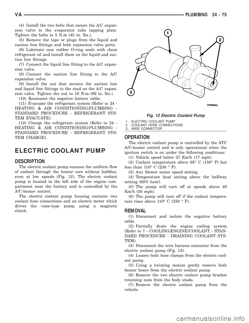
The electric coolant pump ensures the uniform flow
of coolant through the heater core without bubbles,
even at low speeds (Fig. 12). The electric coolant
pump is located in the left side of the engine com-
partment near the battery and is controlled by the
A/C-heater control.
The electric coolant pump housing contains two
coolant hose connections and an electric motor which
drives the vane-type pump using a magnetic
clutch.
OPERATION
The electric coolant pump is controlled by the ATC
A/C-heater control and is only operational when the
ignition switch is on under the following conditions:
(1) Vehicle speed below 27 Km/h (17 mph).
(2) Coolant temperature above 65É C (150É F) but
less than 110É C (230 É F).
(3) Any blower motor speed setting.
(4) Temperature heat setting above the halfway
setting (60% heat).
(5) The pump will turn off at speeds above 48
Km/h (30 mph).
(6) The pump will turn off if the coolant tempera-
ture rises above 110É C (230 É F).
REMOVAL
(1) Disconnect and isolate the negative battery
cable.
(2) Partially drain the engine cooling system
(Refer to 7 - COOLING/ENGINE/COOLANT - STAN-
DARD PROCEDURE - DRAINING COOLANT SYS-
TEM).
(3) Disconnect the wire harness connector from the
electric coolant pump (Fig. 13).
(4) Loosen both hose clamps from the electric cool-
ant pump.
(5) Using a twisting motion gently remove both
heater hoses from the electric coolant pump.
(6) Remove the two electric coolant pump bracket
retaining nuts from the body studs.
(7) Remove the electric coolant pump from the
vehicle.
Fig. 12 Electric Coolant Pump
1 - ELECTRIC COOLANT PUMP
2 - COOLANT HOSE CONNECTIONS
3 - WIRE CONNECTOR
VAPLUMBING 24 - 75
Page 2141 of 2305
CABIN HEATER
TABLE OF CONTENTS
page page
CABIN HEATER
DESCRIPTION........................104
OPERATION..........................104
DIAGNOSIS AND TESTING
SUPPLEMENTAL CABIN HEATER........104
EXHAUST TUBE
REMOVAL............................105
INSTALLATION........................106
FUEL DOSING PUMP
DESCRIPTION........................106
OPERATION..........................106
REMOVAL............................106
INSTALLATION........................107
FUEL LINE
STANDARD PROCEDURE
CLEANING.........................107REMOVAL............................108
INSTALLATION........................109
HEATER UNIT
REMOVAL
HEATER UNIT.......................110
WIRE HARNESS.....................110
INSTALLATION
HEATER UNIT.......................110
WIRE HARNESS.....................111
INLET HOSE
REMOVAL............................111
INSTALLATION........................112
CABIN HEATER
DESCRIPTION
Vehicles equipped with the diesel engine are also
equipped with a supplemental cabin heater. This
cabin heater is mounted under the vehicle and oper-
ates similar to an oil fired furnace. The heater burns
small amounts of fuel to provide additional heat to
the coolant. Coolant is routed from the engine, to the
supplemental cabin heater and then to the front
heater core. This provides additional heat to the pas-
senger compartment. The supplemental cabin heater
system is interfaced to the vehicles on-board com-
puter systems and DRBIIItdiagnostics.
The supplemental cabin heater has an electronic
control module that monitors the heat output of the
heater. The cabin heater operates at full load (5 kW),
half load or idle mode (no additional heat) depending
on engine coolant temperature.
OPERATION
The supplemental cabin heater is activated by
using the temperature control on the A/C-heater con-
trol. The supplemental cabin heater is activated
when the temperature control is set to/or above the
upper set point. The supplemental cabin heater can
operate in a full or partial load range as well as an
idle mode, all dependent on the engine coolant tem-
perature. The heater unit will also turn off if the
temperature control is set to less than the lower set
point. The supplemental cabin heater can take up to
three minutes to completely shut down when eitherthe heater temperature is set below the lower set
point or the vehicle ignition is turned off.
The supplemental cabin heater only operates when
the engine is running, the mileage exceeds 8 kilome-
ter (5 mph) and the fuel tank volume exceeds 1/8 of a
tank. The heater should start if the coolant temper-
ature is below 40É C (104É F).
NOTE: Do not apply a strong vacuum directly on
the supplemental cabin heater exhaust line. Place
the vacuum within 75 mm (3 inches) of the exhaust
port. Too strong of a vacuum can prevent the heater
from starting. The heater control module monitors
the blower speed and combustion during its start-
up.
DIAGNOSIS AND TESTING
SUPPLEMENTAL CABIN HEATER
Refer to the Symptoms Diagnosis table for basic
checks of the diesel fueled supplemental cabin heater.
24 - 104 CABIN HEATERVA
Page 2146 of 2305
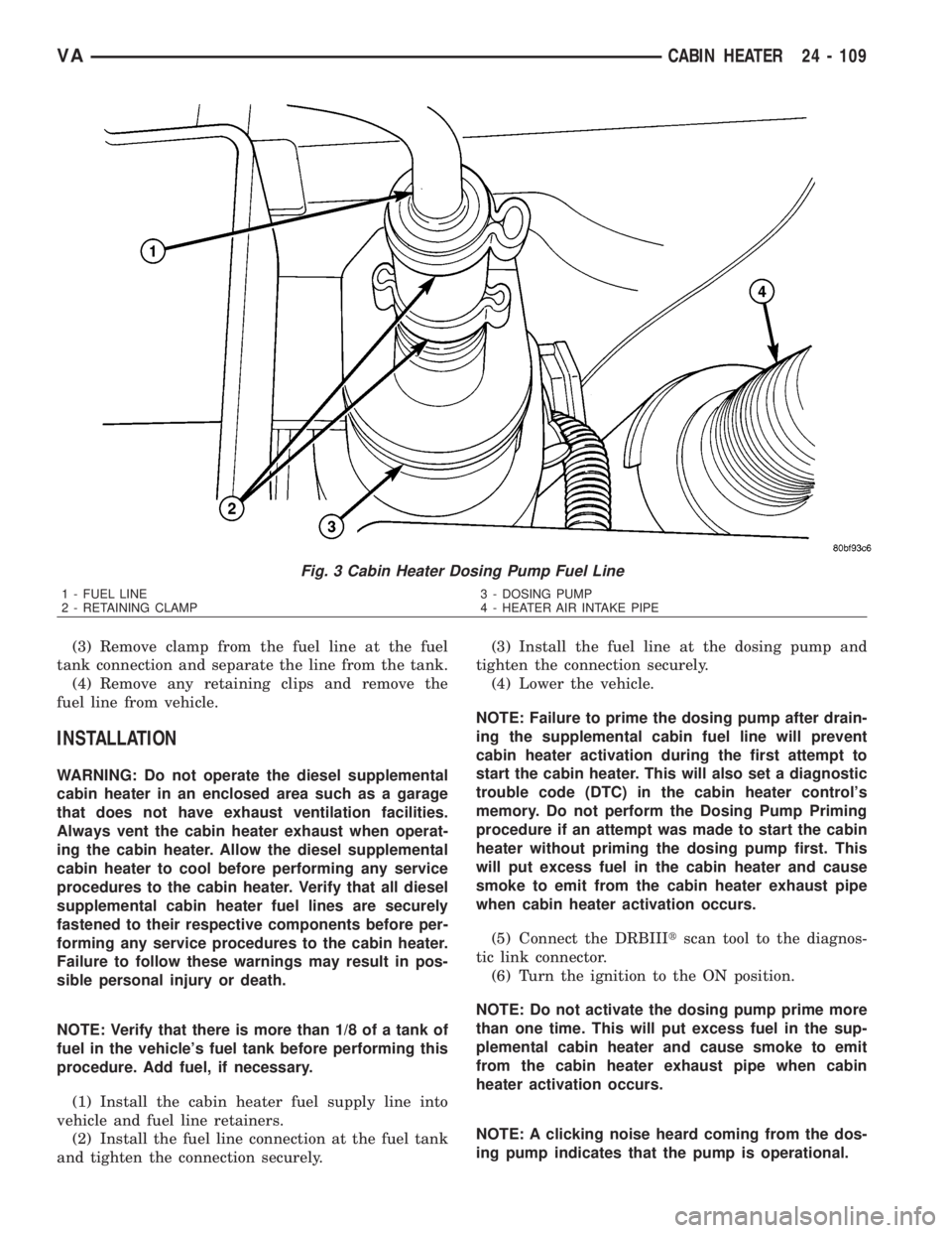
(3) Remove clamp from the fuel line at the fuel
tank connection and separate the line from the tank.
(4) Remove any retaining clips and remove the
fuel line from vehicle.
INSTALLATION
WARNING: Do not operate the diesel supplemental
cabin heater in an enclosed area such as a garage
that does not have exhaust ventilation facilities.
Always vent the cabin heater exhaust when operat-
ing the cabin heater. Allow the diesel supplemental
cabin heater to cool before performing any service
procedures to the cabin heater. Verify that all diesel
supplemental cabin heater fuel lines are securely
fastened to their respective components before per-
forming any service procedures to the cabin heater.
Failure to follow these warnings may result in pos-
sible personal injury or death.
NOTE: Verify that there is more than 1/8 of a tank of
fuel in the vehicle's fuel tank before performing this
procedure. Add fuel, if necessary.
(1) Install the cabin heater fuel supply line into
vehicle and fuel line retainers.
(2) Install the fuel line connection at the fuel tank
and tighten the connection securely.(3) Install the fuel line at the dosing pump and
tighten the connection securely.
(4) Lower the vehicle.
NOTE: Failure to prime the dosing pump after drain-
ing the supplemental cabin fuel line will prevent
cabin heater activation during the first attempt to
start the cabin heater. This will also set a diagnostic
trouble code (DTC) in the cabin heater control's
memory. Do not perform the Dosing Pump Priming
procedure if an attempt was made to start the cabin
heater without priming the dosing pump first. This
will put excess fuel in the cabin heater and cause
smoke to emit from the cabin heater exhaust pipe
when cabin heater activation occurs.
(5) Connect the DRBIIItscan tool to the diagnos-
tic link connector.
(6) Turn the ignition to the ON position.
NOTE: Do not activate the dosing pump prime more
than one time. This will put excess fuel in the sup-
plemental cabin heater and cause smoke to emit
from the cabin heater exhaust pipe when cabin
heater activation occurs.
NOTE: A clicking noise heard coming from the dos-
ing pump indicates that the pump is operational.
Fig. 3 Cabin Heater Dosing Pump Fuel Line
1 - FUEL LINE
2 - RETAINING CLAMP3 - DOSING PUMP
4 - HEATER AIR INTAKE PIPE
VACABIN HEATER 24 - 109
Page 2154 of 2305
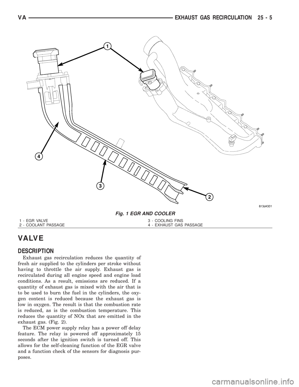
VA LV E
DESCRIPTION
Exhaust gas recirculation reduces the quantity of
fresh air supplied to the cylinders per stroke without
having to throttle the air supply. Exhaust gas is
recirculated during all engine speed and engine load
conditions. As a result, emissions are reduced. If a
quantity of exhaust gas is mixed with the air that is
to be used to burn the fuel in the cylinders, the oxy-
gen content is reduced because the exhaust gas is
low in oxygen. The result is that the combustion rate
is reduced, as is the combustion temperature. This
reduces the quantity of NOx that are emitted in the
exhaust gas. (Fig. 2).
The ECM power supply relay has a power off delay
feature. The relay is powered off approximately 15
seconds after the ignition switch is turned off. This
allows for the self-cleaning function of the EGR valve
and a function check of the sensors for diagnosis pur-
poses.
Fig. 1 EGR AND COOLER
1 - EGR VALVE 3 - COOLING FINS
2 - COOLANT PASSAGE 4 - EXHAUST GAS PASSAGE
VAEXHAUST GAS RECIRCULATION 25 - 5
Page 2155 of 2305
OPERATION
The mass of the air supplied to the cylinders per
stroke is the decisive factor for determining the opti-
mum quantity of exhaust gas for the operating con-
dition. This is calculated from the Mass Air Flow
sensor information.
The ECM evaluates this signal as well as that
from the Charge Air Pressure sensor, and outputs a
PWM signal in accordance with one of the maps
stored in it. The signal is sent to the exhaust gas
recirculation valve. The map is formulated to keep
the NOx as low as possible. The EGR valve is actu-
ated by an electric positioning motor and has a self
cleaning function. Every time the ignition switch is
turned off, the valve rotates twice to eliminate any
carbon deposits.
REMOVAL
NOTE: The EGR and EGR Cooler are serviced as an
assembly.
(1) Disconnect the negative battery cable.
(2) Partailly drain the cooling system (Refer to 7 -
COOLING/ENGINE/COOLANT - STANDARD PRO-
CEDURE).
(3) Lift up on the charge air hose retaining clip at
the intake manifold and disconnect hose with seal
(4) Disconnect the electrical connector at the EGR
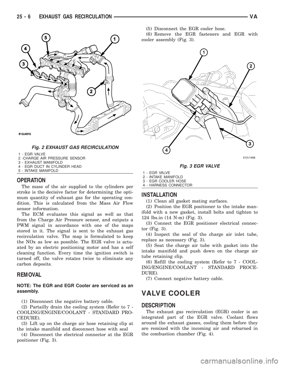
positioner (Fig. 3).(5) Disconnect the EGR cooler hose.
(6) Remove the EGR fasteners and EGR with
cooler assembly (Fig. 3).
INSTALLATION
(1) Clean all gasket mating surfaces.
(2) Position the EGR positioner to the intake man-
ifold with a new gasket, install bolts and tighten to
124 lbs.in (14 N´m) (Fig. 3).
(3) Connect the EGR positioner electrical connec-
tor (Fig. 3).
(4) Inspect the seal of the charge air inlet tube,
replace as necessary (Fig. 3).
(5) Seat the charge air tube with gasket into the
intake manifold and push down on the charge air
tube retaining clip.
(6) Refill the cooling system (Refer to 7 - COOL-
ING/ENGINE/COOLANT - STANDARD PROCE-
DURE).
(7) Connect negative battery cable.
VALVE COOLER
DESCRIPTION
The exhaust gas recirculation (EGR) cooler is an
integrated part of the EGR valve. Coolant flows
around the exhaust gasses, cooling them before they
are remixed with the incoming air and reburned in
the combustion chamber (Fig. 4).
Fig. 2 EXHAUST GAS RECIRCULATION
1 - E G R VA LV E
2 -CHARGE AIR PRESSURE SENSOR
3 - EXHAUST MANIFOLD
4 - EGR DUCT IN CYLINDER HEAD
5 - INTAKE MANIFOLD
Fig. 3 EGR VALVE
1 - E G R VA LV E
2 - INTAKE MANIFOLD
3 - EGR COOLER HOSE
4 - HARNESS CONNECTOR
25 - 6 EXHAUST GAS RECIRCULATIONVA