2006 MERCEDES-BENZ SPRINTER ignition
[x] Cancel search: ignitionPage 1503 of 2305
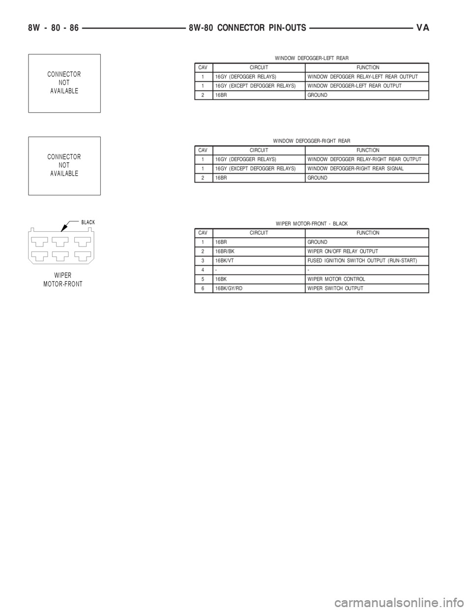
WINDOW DEFOGGER-LEFT REAR
CAV CIRCUIT FUNCTION
1 16GY (DEFOGGER RELAYS) WINDOW DEFOGGER RELAY-LEFT REAR OUTPUT
1 16GY (EXCEPT DEFOGGER RELAYS) WINDOW DEFOGGER-LEFT REAR OUTPUT
2 16BR GROUND
WINDOW DEFOGGER-RIGHT REAR
CAV CIRCUIT FUNCTION
1 16GY (DEFOGGER RELAYS) WINDOW DEFOGGER RELAY-RIGHT REAR OUTPUT
1 16GY (EXCEPT DEFOGGER RELAYS) WINDOW DEFOGGER-RIGHT REAR SIGNAL
2 16BR GROUND
WIPER MOTOR-FRONT - BLACK
CAV CIRCUIT FUNCTION
1 16BR GROUND
2 16BR/BK WIPER ON/OFF RELAY OUTPUT
3 16BK/VT FUSED IGNITION SWITCH OUTPUT (RUN-START)
4- -
5 16BK WIPER MOTOR CONTROL
6 16BK/GY/RD WIPER SWITCH OUTPUT
8W - 80 - 86 8W-80 CONNECTOR PIN-OUTSVA
Page 1509 of 2305
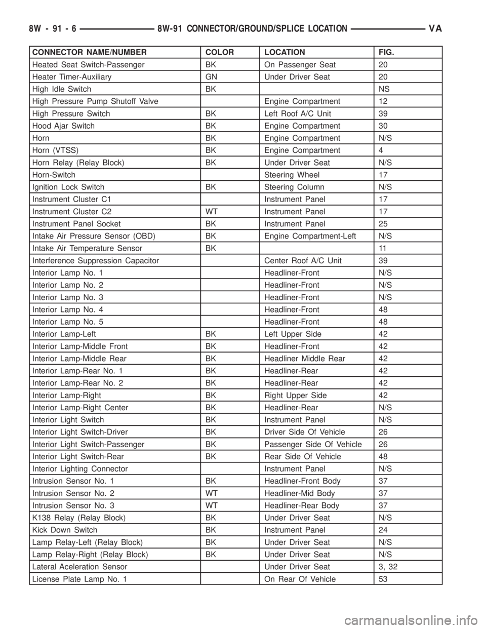
CONNECTOR NAME/NUMBER COLOR LOCATION FIG.
Heated Seat Switch-Passenger BK On Passenger Seat 20
Heater Timer-Auxiliary GN Under Driver Seat 20
High Idle Switch BK NS
High Pressure Pump Shutoff Valve Engine Compartment 12
High Pressure Switch BK Left Roof A/C Unit 39
Hood Ajar Switch BK Engine Compartment 30
Horn BK Engine Compartment N/S
Horn (VTSS) BK Engine Compartment 4
Horn Relay (Relay Block) BK Under Driver Seat N/S
Horn-Switch Steering Wheel 17
Ignition Lock Switch BK Steering Column N/S
Instrument Cluster C1 Instrument Panel 17
Instrument Cluster C2 WT Instrument Panel 17
Instrument Panel Socket BK Instrument Panel 25
Intake Air Pressure Sensor (OBD) BK Engine Compartment-Left N/S
Intake Air Temperature Sensor BK 11
Interference Suppression Capacitor Center Roof A/C Unit 39
Interior Lamp No. 1 Headliner-Front N/S
Interior Lamp No. 2 Headliner-Front N/S
Interior Lamp No. 3 Headliner-Front N/S
Interior Lamp No. 4 Headliner-Front 48
Interior Lamp No. 5 Headliner-Front 48
Interior Lamp-Left BK Left Upper Side 42
Interior Lamp-Middle Front BK Headliner-Front 42
Interior Lamp-Middle Rear BK Headliner Middle Rear 42
Interior Lamp-Rear No. 1 BK Headliner-Rear 42
Interior Lamp-Rear No. 2 BK Headliner-Rear 42
Interior Lamp-Right BK Right Upper Side 42
Interior Lamp-Right Center BK Headliner-Rear N/S
Interior Light Switch BK Instrument Panel N/S
Interior Light Switch-Driver BK Driver Side Of Vehicle 26
Interior Light Switch-Passenger BK Passenger Side Of Vehicle 26
Interior Light Switch-Rear BK Rear Side Of Vehicle 48
Interior Lighting Connector Instrument Panel N/S
Intrusion Sensor No. 1 BK Headliner-Front Body 37
Intrusion Sensor No. 2 WT Headliner-Mid Body 37
Intrusion Sensor No. 3 WT Headliner-Rear Body 37
K138 Relay (Relay Block) BK Under Driver Seat N/S
Kick Down Switch BK Instrument Panel 24
Lamp Relay-Left (Relay Block) BK Under Driver Seat N/S
Lamp Relay-Right (Relay Block) BK Under Driver Seat N/S
Lateral Aceleration Sensor Under Driver Seat 3, 32
License Plate Lamp No. 1 On Rear Of Vehicle 53
8W - 91 - 6 8W-91 CONNECTOR/GROUND/SPLICE LOCATIONVA
Page 1571 of 2305
OPERATION
The cigar lighter consists of two major components:
a knob and heating element unit, and the cigar
lighter base or receptacle shell. The receptacle shell
is connected to ground, and an insulated contact in
the bottom of the shell is connected to battery cur-
rent. The cigar lighter receives battery voltage from a
fuse in the fuseblock only when the ignition switch is
in the Accessory or On positions.
The knob and heating element are encased within
a spring-loaded housing, which also features a sliding
protective heat shield. When the heating element is
inserted in the receptacle shell, the heating element
resistor coil is grounded through its housing to the
receptacle shell. If the cigar lighter knob is pushed
inward, the heat shield slides up toward the knob
exposing the heating element.
Two small spring-clip retainers are located on
either side of the insulated contact inside the bottom
of the receptacle shell. These clips engage and hold
the heating element against the insulated contact
long enough for the resistor coil to heat up and glow.
When the resistor coil becomes sufficiently heated,
excess heat radiates from the heating element caus-
ing the spring-clips to expand. Once the spring-clips
expand far enough to release the heating element,
the spring-loaded housing forces the knob and heat-
ing element to pop back outward to their relaxed
position. When the cigar lighter knob and element
are pulled out of the receptacle shell, the protective
heat shield slides downward on the housing so that
the heating element is recessed and shielded around
its circumference for safety.
DIAGNOSIS AND TESTING - CIGAR LIGHTER
OUTLET
For cigar lighter outlet diagnosis and testing pro-
cedures (Refer to 8 - ELECTRICAL/POWER DISTRI-
BUTION/POWER OUTLET - DIAGNOSIS AND
TESTING)
REMOVAL
For cigar lighter outlet removal procedure (Refer to
8 - ELECTRICAL/POWER DISTRIBUTION/POWER
OUTLET - REMOVAL).
CIRCUIT BREAKER
DESCRIPTION
Automatic resetting circuit breakers are used to
protect the power window voltage supply circuits.
These circuit breakers can protect the systems from a
short circuit, or from an overload condition caused byan obstructed or stuck power window regulator or
switch.
The circuit breaker cannot be repaired and, if
faulty or damaged, it must be replaced.
OPERATION
The circuit breaker contains a bi-metal strip sand-
wiched between two contacts forming the connection
in the circuit. An overload condition causes the
bi-metal strip to heat and bend to the open position,
disconnecting current flow to the circuit. Then as the
system overload or short circuit is removed, the
bi-metal strip cools, re-establishing contact to allow
current flow to the circuit.
DIAGNOSIS AND TESTING - CIRCUIT BREAKER
For complete circuit descriptions and diagrams,
refer toWiring.
(1) Locate the correct circuit breaker in the fuse-
block. Pull out the circuit breaker slightly, but be cer-
tain that the circuit breaker terminals still contact
the terminals in the fuseblock cavities.
(2) Connect the negative lead of a 12-volt DC volt-
meter to a good ground.
(3) With the voltmeter positive lead, check both
terminals of the circuit breaker for battery voltage.
If only one terminal has battery voltage, the circuit
breaker is faulty and must be replaced. If neither ter-
minal has battery voltage, repair the open circuit
from the Power Distribution Center as required.
FUSE BLOCK #1
DESCRIPTION
An electrical fuse block is concealed under the
driver side steering column. The fuse block serves to
distribute electrical current to many of the electrical
systems in the vehicle. The fuse block contains blade-
type mini fuses, relays and micro processors that
enable automatic control of some of the power distri-
bution circuits throughout the vehicle.
The molded plastic fuse block housing has an inte-
gral mounting bracket that is secured with screws to
the steering column. A finger recess is molded into
the cover for easy removal. A fuse layout map is
molded onto the back side of the cover to ensure
proper fuse identification.
The fuse block cannot be repaired, if the fuse block
is faulty or damaged or if any internal circuit is
faulty or damaged, the entire fuse block must be
replaced.
8W - 97 - 2 8W-97 POWER DISTRIBUTIONVA
Page 1573 of 2305
repaired and, if faulty or damaged, it must be
replaced.
OPERATION
The power outlet base or receptacle shell is con-
nected to ground, and an insulated contact in the
bottom of the shell is connected to battery current.
The power outlet receives battery voltage from a fuse
in the fuse block at all times.
DIAGNOSIS AND TESTING - POWER OUTLET
(1) Check for battery voltage at the fused B(+) fuse
in the fuse block. If OK, go to Step 2. If not OK,
repair the open fused B(+) circuit to the battery as
required.
(2) Check for continuity between the inside cir-
cumference of the power outlet receptacle and a good
ground. There should be continuity. If OK, go to Step
3. If not OK, go to Step 4.
(3) Check for battery voltage at the insulated con-
tact located at the back of the power outlet recepta-
cle. If not OK, go to Step 4.
(4) Disconnect and isolate the battery negative
cable. Check for continuity between the ground cir-
cuit cavity of the power outlet wire harness connector
and a good ground. There should be continuity. If
OK, go to Step 5. If not OK, repair the open ground
circuit to ground as required.
(5) Connect the battery negative cable. Check for
battery voltage at the fused B(+) circuit cavity of the
power outlet wire harness connector. If OK, replace
the faulty power outlet receptacle. If not OK, repair
the open fused B(+) circuit to the fuse in the fuse
block as required.
REMOVAL
(1) Disconnect and isolate the battery negative
cable.
(2) Pull the cigar lighter knob and element out of
the cigar lighter receptacle base, or unsnap the pro-
tective cap from the power outlet receptacle base.
(3) Look inside the cigar lighter or power outlet
receptacle base and note the position of the rectangu-
lar retaining bosses of the mount that secures the
receptacle base to the instrument panel.
(4) Insert a pair of external snap ring pliers into
the cigar lighter or power outlet receptacle base and
engage the tips of the pliers with the retaining
bosses of the mount.
(5) Squeeze the pliers to disengage the mount
retaining bosses from the receptacle base and, using
a gentle rocking motion, pull the pliers and the
receptacle base out of the mount.
(6) Disconnect the instrument panel wire harness
connector from the connector receptacle of the cigar
lighter or the power outlet receptacle base.(7) Remove the cigar lighter or power outlet mount
from the instrument panel.
INSTALLATION
(1) Install the cigar lighter or power outlet mount
into the instrument panel.
(2) Reconnect the instrument panel wire harness
connector to the connector receptacle of the cigar
lighter or the power outlet receptacle base.
(3) Align the splines on the outside of the cigar
lighter or power outlet receptacle base connector
receptacle with the grooves on the inside of the
mount.
(4) Press firmly on the cigar lighter or power out-
let receptacle base until the retaining bosses of the
mount are fully engaged in their receptacles.
(5) Install the cigar lighter knob and element into
the cigar lighter receptacle base.
(6) Reconnect the battery negative cable.
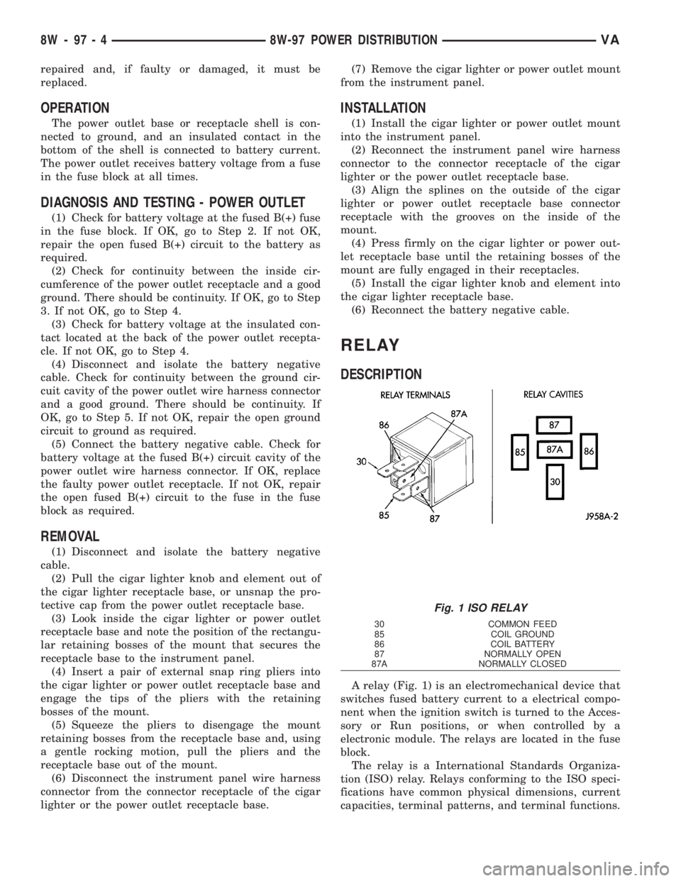
RELAY
DESCRIPTION
A relay (Fig. 1) is an electromechanical device that
switches fused battery current to a electrical compo-
nent when the ignition switch is turned to the Acces-
sory or Run positions, or when controlled by a
electronic module. The relays are located in the fuse
block.
The relay is a International Standards Organiza-
tion (ISO) relay. Relays conforming to the ISO speci-
fications have common physical dimensions, current
capacities, terminal patterns, and terminal functions.
Fig. 1 ISO RELAY
30 COMMON FEED
85 COIL GROUND
86 COIL BATTERY
87 NORMALLY OPEN
87A NORMALLY CLOSED
8W - 97 - 4 8W-97 POWER DISTRIBUTIONVA
Page 1574 of 2305
A relay cannot be repaired or adjusted and, if
faulty or damaged, it must be replaced.
OPERATION
The ISO relay consists of an electromagnetic coil, a
resistor and three (two fixed and one movable) elec-
trical contacts. The movable (common feed) relay con-
tact is held against one of the fixed contacts
(normally closed) by spring pressure. When the elec-
tromagnetic coil is energized, it draws the movable
contact away from the normally closed fixed contact,
and holds it against the other (normally open) fixed
contact.
When the electromagnetic coil is de-energized,
spring pressure returns the movable contact to the
normally closed position. The resistor is connected in
parallel with the electromagnetic coil in the relay,
and helps to dissipate voltage spikes that are pro-
duced when the coil is de-energized.
DIAGNOSIS AND TESTING - RELAY
(1) Remove the relay from its mounting location.
(2) A relay in the de-energized position should
have continuity between terminals 87A and 30, and
no continuity between terminals 87 and 30. If OK, go
to Step 3. If not OK, replace the faulty relay.
(3) Resistance between terminals 85 and 86 (elec-
tromagnet) should be 60.7 - 80.3 ohms. If OK, go to
Step 4. If not OK, replace the faulty relay.
(4) Connect a battery to terminals 85 and 86.
There should now be continuity between terminals
30 and 87, and no continuity between terminals 87A
and 30. If OK, perform the Relay Circuit Test that
follows. If not OK, replace the faulty relay.
DIAGNOSIS AND TESTING - RELAY CIRCUIT TEST
(1) The relay common feed terminal cavity (30) of
the fuse block is connected to battery voltage and
should be hot at all times. Check for battery voltage
at the fused B(+) circuit cavity in the fuse block
receptacle for the relay. If OK, go to Step 2. If not
OK, repair the fused B(+) circuit to the fuse block
fuse as required.
(2) The relay normally closed terminal (87A) is
connected to terminal 30 in the de-energized position,
but is not used for this application. Go to Step 3.
(3) The relay normally open terminal (87) is con-
nected to the common feed terminal (30) in the ener-
gized position. This terminal supplies battery voltage
to the fused B(+) fuse in the fuse block that feeds the
accessory when the relay is energized by the ignition
switch. There should be continuity between the fuse
block cavity for relay terminal 87 and the fused B(+)
fuse in the fuse block at all times. If OK, go to Step
4. If not OK, repair the open fused B(+) circuit to the
fuse block fuse as required.(4) The coil ground terminal (85) is connected to
the electromagnet in the relay. It receives battery
feed to energize the relay when the ignition switch is
in the Accessory or Run positions. Turn the ignition
switch to the On position. Check for battery voltage
at the fused ignition switch output (acc/run) circuit
cavity for relay terminal 85 in the fuse block recep-
tacle for the relay. If OK, go to Step 5. If not OK,
repair the open fused ignition switch output (acc/run)
circuit to the ignition switch as required.
(5) The coil battery terminal (86) is connected to
the electromagnet in the relay. The fuse block cavity
for this terminal should have continuity to ground at
all times. If not OK, repair the open ground circuit to
ground as required.
REMOVAL
(1) Disconnect and isolate the negative battery
cable.
(2) Remove the relay by grasping it firmly and
pulling it straight out from its receptacle. A slight
back and fourth rocking motion may help the
removal process.
INSTALLATION
(1) Position the relay to the proper receptacle.
(2) Align the relay terminals with the terminal
cavities in the receptacle.
(3) Push firmly and evenly on the top of the relay
until the terminals are fully seated in the terminal
cavities in the receptacle.
(4) Connect the negative battery cable.
VA8W-97 POWER DISTRIBUTION 8W - 97 - 5
Page 1578 of 2305
DESCRIPTION SPECIFICATION
Engine 2.7L CDI
Engine Description 5 Cylinder In-Line En-
gine With 4-Valve Tech-
nology
Air Intake Turbo-Charged Engine
with Charge Air Cooling
Fuel Injection System 2 nd. Generation Com-
mon Rail Direct Injection
(CDI)
Fuel Diesel
Firing Order 1-2-4-5-3
Rated Output 154 HP at 3800 RPM
Torque 243 ft. lbs. at 1600-2400
RPM
Maximum Speed 4800 RPM
Compression Ratio 18:1
Bore/Stroke 3.46/3.48
Eff. Displacement 2688 cm3
STANDARD PROCEDURE
STANDARD PROCEDURE - COMPRESSION
TESTING ENGINE
(1) Warm up engine to operating temperature
(approx. 80 ÉC, 176ÉF).
(2) Shut off engine.
(3) Remove engine cover (Refer to 9 - ENGINE -
REMOVAL).
(4) Remove glow plugs (Refer to 8 - ELECTRICAL/
IGNITION CONTROL/GLOW PLUG - REMOVAL).
(5) Crank engine several times with the starter to
eliminate combustion residues in the cylinders.
(6) Insert compression tester adapter #8927 (Refer
to 9 - ENGINE - SPECIAL TOOLS) with check valve
installed into glow plug hole of cylinder to be tested.
(7) Connect compression tester hose adapter #9295
to compression gauge and test compression pressure
by cranking engine with starter for at least 8 revolu-
tions.
(8) Carry out test procedure at the remaining cyl-
inders in the same way.
(9) Compare pressure readings obtained with the
specified pressures. If the pressure reading is below
the minimum compression pressure or if the permis-
sible difference between the individual cylinders is
exceeded. Refer to cylinder leak down test.
(10) Remove compression tester and adapter from
cylinder head.
(11) Install glow plugs (Refer to 8 - ELECTRICAL/
IGNITION CONTROL/GLOW PLUG - INSTALLA-
TION).(12) Install engine cover (Refer to 9 - ENGINE -
INSTALLATION).
COMPRESSION SPECIFICATIONS
Maximum Compression 29-35 bar (420-507 psi)
Minimum Compression 18bar (261 psi)
Permissible Difference
Between Cylinders 3bar ( 44 psi)
STANDARD PROCEDURE - CYLINDER LEAK
DOWN TEST
(1) Warm engine to operating temperature.
WARNING: DO NOT OPEN COOLING SYSTEM
UNLESS COOLANT TEMPERATURE IS BELOW 90C
(194ÉF). RISK OF INJURY TO SKIN AND EYES AS A
RESULT OF SCALDING WITH HOT COOLANT
WHICH SPLASHES OUT. RISK OF POISONING
FROM SWALLOWING COOLANT. OPEN CAP
SLOWLY AND RELEASE PRESSURE. STORE COOL-
ANT IN PROPER CONTAINERS ONLY. WEAR PRO-
TECTIVE GLOVES, CLOTHING AND EYE
PROTECTION.
NOTE: Turn cap carefully as far as first detent,
release pressure, then unscrew cap.
(2) Open cooling system cap at coolant recover
pressure container.
(3) Remove engine cover (Refer to 9 - ENGINE -
REMOVAL).
(4) Unscrew oil filler cap.
(5) Remove glow plugs (Refer to 8 - ELECTRICAL/
IGNITION CONTROL/GLOW PLUG - REMOVAL).
NOTE: Crank engine at crankshaft in direction of
rotation of the engine (clockwise).
(6) Position cylinder to be tested to ignition Top
Dead Center (DTC).
NOTE: Calibrate cylinder leak down tester and
remove check valve in screw-in fitting.
(7) Connect cylinder leak down tester and follow
INSPECTING Instruction.
INSPECTING
NOTE: If crankshaft rotates, install retaining lock for
crankshaft/ring gear.
(1) Pressurize cylinder with compressed air and
read off pressure loss at cylinder leak tester. If exces-
sive pressure loss exists, determine possible cause
(Refer to 9 - ENGINE - STANDARD PROCEDURE).
VAENGINE 9 - 3
Page 1598 of 2305
NOTE: The camshaft housing Must Not be
machined. Basic bore of the camshaft bearings will
be altered.
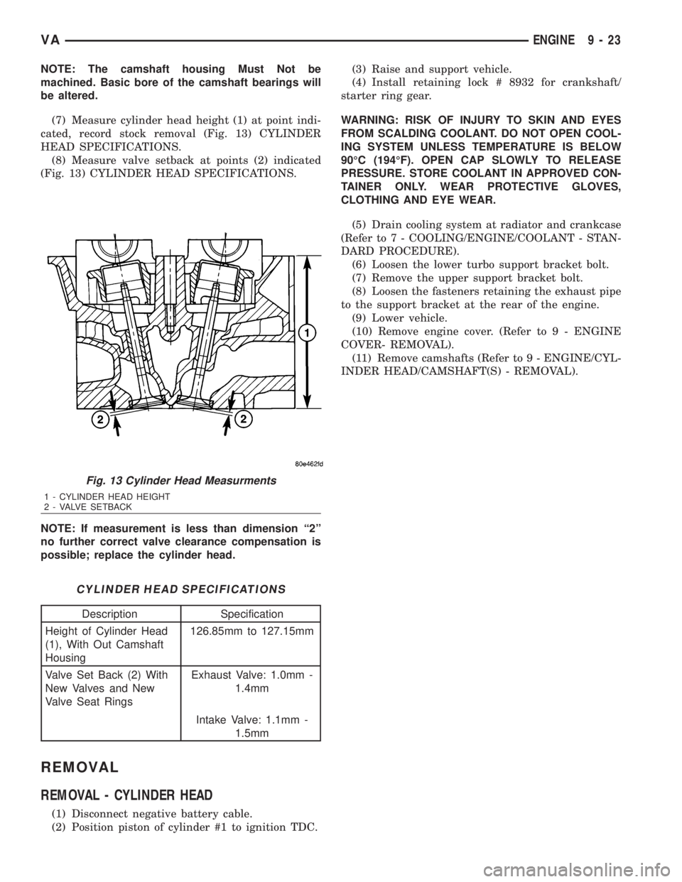
(7) Measure cylinder head height (1) at point indi-
cated, record stock removal (Fig. 13) CYLINDER
HEAD SPECIFICATIONS.
(8) Measure valve setback at points (2) indicated
(Fig. 13) CYLINDER HEAD SPECIFICATIONS.
NOTE: If measurement is less than dimension ª2º
no further correct valve clearance compensation is
possible; replace the cylinder head.
CYLINDER HEAD SPECIFICATIONS
Description Specification
Height of Cylinder Head
(1), With Out Camshaft
Housing126.85mm to 127.15mm
Valve Set Back (2) With
New Valves and New
Valve Seat RingsExhaust Valve: 1.0mm -
1.4mm
Intake Valve: 1.1mm -
1.5mm
REMOVAL
REMOVAL - CYLINDER HEAD
(1) Disconnect negative battery cable.
(2) Position piston of cylinder #1 to ignition TDC.(3) Raise and support vehicle.
(4) Install retaining lock # 8932 for crankshaft/
starter ring gear.
WARNING: RISK OF INJURY TO SKIN AND EYES
FROM SCALDING COOLANT. DO NOT OPEN COOL-
ING SYSTEM UNLESS TEMPERATURE IS BELOW
90ÉC (194ÉF). OPEN CAP SLOWLY TO RELEASE
PRESSURE. STORE COOLANT IN APPROVED CON-
TAINER ONLY. WEAR PROTECTIVE GLOVES,
CLOTHING AND EYE WEAR.
(5) Drain cooling system at radiator and crankcase
(Refer to 7 - COOLING/ENGINE/COOLANT - STAN-
DARD PROCEDURE).
(6) Loosen the lower turbo support bracket bolt.
(7) Remove the upper support bracket bolt.
(8) Loosen the fasteners retaining the exhaust pipe
to the support bracket at the rear of the engine.
(9) Lower vehicle.
(10) Remove engine cover. (Refer to 9 - ENGINE
COVER- REMOVAL).
(11) Remove camshafts (Refer to 9 - ENGINE/CYL-
INDER HEAD/CAMSHAFT(S) - REMOVAL).
Fig. 13 Cylinder Head Measurments
1 - CYLINDER HEAD HEIGHT
2 - VALVE SETBACK
VAENGINE 9 - 23
Page 1600 of 2305
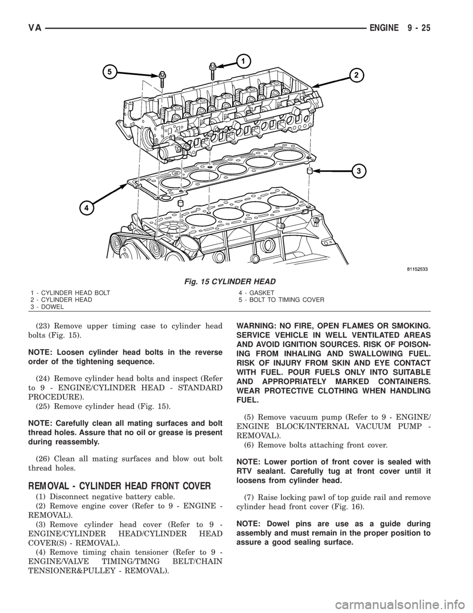
(23) Remove upper timing case to cylinder head
bolts (Fig. 15).
NOTE: Loosen cylinder head bolts in the reverse
order of the tightening sequence.
(24) Remove cylinder head bolts and inspect (Refer
to 9 - ENGINE/CYLINDER HEAD - STANDARD
PROCEDURE).
(25) Remove cylinder head (Fig. 15).
NOTE: Carefully clean all mating surfaces and bolt
thread holes. Assure that no oil or grease is present
during reassembly.
(26) Clean all mating surfaces and blow out bolt
thread holes.
REMOVAL - CYLINDER HEAD FRONT COVER
(1) Disconnect negative battery cable.
(2) Remove engine cover (Refer to 9 - ENGINE -
REMOVAL).
(3) Remove cylinder head cover (Refer to 9 -
ENGINE/CYLINDER HEAD/CYLINDER HEAD
COVER(S) - REMOVAL).
(4) Remove timing chain tensioner (Refer to 9 -
ENGINE/VALVE TIMING/TMNG BELT/CHAIN
TENSIONER&PULLEY - REMOVAL).WARNING: NO FIRE, OPEN FLAMES OR SMOKING.
SERVICE VEHICLE IN WELL VENTILATED AREAS
AND AVOID IGNITION SOURCES. RISK OF POISON-
ING FROM INHALING AND SWALLOWING FUEL.
RISK OF INJURY FROM SKIN AND EYE CONTACT
WITH FUEL. POUR FUELS ONLY INTO SUITABLE
AND APPROPRIATELY MARKED CONTAINERS.
WEAR PROTECTIVE CLOTHING WHEN HANDLING
FUEL.
(5) Remove vacuum pump (Refer to 9 - ENGINE/
ENGINE BLOCK/INTERNAL VACUUM PUMP -
REMOVAL).
(6) Remove bolts attaching front cover.
NOTE: Lower portion of front cover is sealed with
RTV sealant. Carefully tug at front cover until it
loosens from cylinder head.
(7) Raise locking pawl of top guide rail and remove
cylinder head front cover (Fig. 16).
NOTE: Dowel pins are use as a guide during
assembly and must remain in the proper position to
assure a good sealing surface.
Fig. 15 CYLINDER HEAD
1 - CYLINDER HEAD BOLT
2 - CYLINDER HEAD
3 - DOWEL4 - GASKET
5 - BOLT TO TIMING COVER
VAENGINE 9 - 25