2006 MERCEDES-BENZ SPRINTER ignition
[x] Cancel search: ignitionPage 1734 of 2305
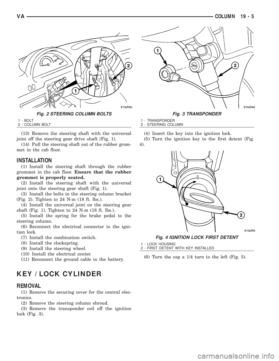
(13) Remove the steering shaft with the universal
joint off the steering gear drive shaft (Fig. 1).
(14) Pull the steering shaft out of the rubber grom-
met in the cab floor.
INSTALLATION
(1) Install the steering shaft through the rubber
grommet in the cab floor.Ensure that the rubber
grommet is properly seated.
(2) Install the steering shaft with the universal
joint onto the steering gear shaft (Fig. 1).
(3) Install the bolts in the steering column bracket
(Fig. 2). Tighten to 24 N´m (18 ft. lbs.).
(4) Install the universal joint on the steering gear
shaft (Fig. 1). Tighten to 24 N´m (18 ft. lbs.).
(5) Install the spring for the brake pedal to the
steering column.
(6) Reconnect the electrical connector to the igni-
tion lock.
(7) Install the combination switch.
(8) Install the clockspring.
(9) Install the steering wheel.
(10) Install the electrical center.
(11) Reconnect the ground cable to the battery.
KEY / LOCK CYLINDER
REMOVAL
(1) Remove the securing cover for the central elec-
tronics.
(2) Remove the steering column shroud.
(3) Remove the transponder coil off the ignition
lock (Fig. 3).(4) Insert the key into the ignition lock.
(5) Turn the ignition key to the first detent (Fig.
4).
(6) Turn the cap a 1/4 turn to the left (Fig. 5).
Fig. 2 STEERING COLUMN BOLTS
1 - BOLT
2 - COLUMN BOLT
Fig. 3 TRANSPONDER
1 - TRANSPONDER
2 - STEERING COLUMN
Fig. 4 IGNITION LOCK FIRST DETENT
1 - LOCK HOUSING
2 - FIRST DETENT WITH KEY INSTALLED
VACOLUMN 19 - 5
Page 1735 of 2305
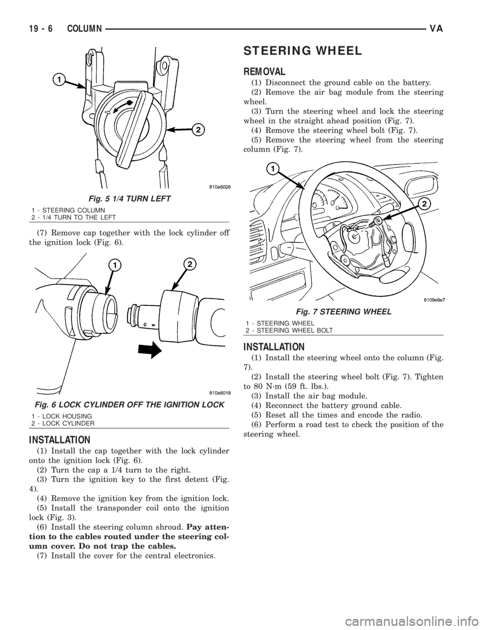
(7) Remove cap together with the lock cylinder off
the ignition lock (Fig. 6).
INSTALLATION
(1) Install the cap together with the lock cylinder
onto the ignition lock (Fig. 6).
(2) Turn the cap a 1/4 turn to the right.
(3) Turn the ignition key to the first detent (Fig.
4).
(4) Remove the ignition key from the ignition lock.
(5) Install the transponder coil onto the ignition
lock (Fig. 3).
(6) Install the steering column shroud.Pay atten-
tion to the cables routed under the steering col-
umn cover. Do not trap the cables.
(7) Install the cover for the central electronics.
STEERING WHEEL
REMOVAL
(1) Disconnect the ground cable on the battery.
(2) Remove the air bag module from the steering
wheel.
(3) Turn the steering wheel and lock the steering
wheel in the straight ahead position (Fig. 7).
(4) Remove the steering wheel bolt (Fig. 7).
(5) Remove the steering wheel from the steering
column (Fig. 7).
INSTALLATION
(1) Install the steering wheel onto the column (Fig.
7).
(2) Install the steering wheel bolt (Fig. 7). Tighten
to 80 N´m (59 ft. lbs.).
(3) Install the air bag module.
(4) Reconnect the battery ground cable.
(5) Reset all the times and encode the radio.
(6) Perform a road test to check the position of the
steering wheel.
Fig. 5 1/4 TURN LEFT
1 - STEERING COLUMN
2 - 1/4 TURN TO THE LEFT
Fig. 6 LOCK CYLINDER OFF THE IGNITION LOCK
1 - LOCK HOUSING
2 - LOCK CYLINDER
Fig. 7 STEERING WHEEL
1 - STEERING WHEEL
2 - STEERING WHEEL BOLT
19 - 6 COLUMNVA
Page 1748 of 2305
flexible adaptation to different vehicle and engine
variants.
EMERGENCY RUNNING FUNCTION
In order to ensure a safe driving state and to pre-
vent damage to the automatic transmission, the TCM
control module switches to limp-home mode in the
event of critical faults. A diagnostic trouble code
(DTC) assigned to the fault is stored in memory. All
solenoid and regulating valves are thus de-energized.
The net effect is:
²The last engaged gear remains engaged.
²The modulating pressure and shift pressures
rise to the maximum levels.
²The torque converter lockup clutch is deacti-
vated.
In order to preserve the operability of the vehicle
to some extent, the hydraulic control can be used to
engage 2nd gear or reverse using the following pro-
cedure:²Stop the vehicle.
²Move selector lever to ªPº.
²Switch off engine.
²Wait at least 10 seconds.
²Start engine.
²Move selector lever to D: 2nd gear.
²Move selector lever to R: Reverse gear.
The limp-home function remains active until the
DTC is rectified or the stored DTC is erased with the
appropriate scan tool. Sporadic faults can be reset
via ignition OFF/ON.
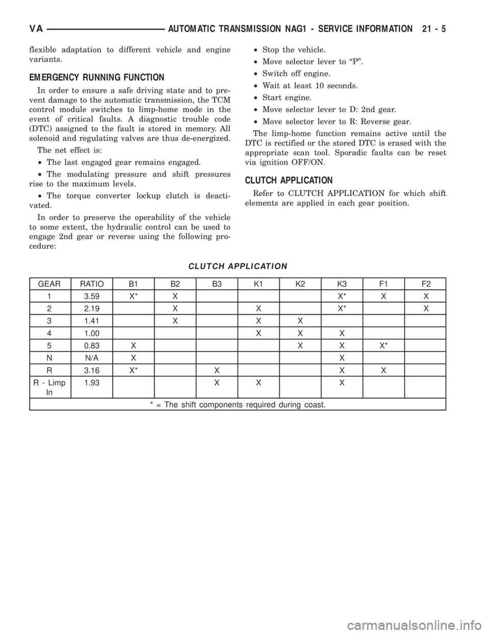
CLUTCH APPLICATION
Refer to CLUTCH APPLICATION for which shift
elements are applied in each gear position.
CLUTCH APPLICATION
GEAR RATIO B1 B2 B3 K1 K2 K3 F1 F2
1 3.59 X* X X* X X
2 2.19 X X X* X
3 1.41 X X X
4 1.00 X X X
5 0.83 X X X X*
N N/A X X
R 3.16 X* X X X
R - Limp
In1.93 X X X
* = The shift components required during coast.
VAAUTOMATIC TRANSMISSION NAG1 - SERVICE INFORMATION 21 - 5
Page 1904 of 2305
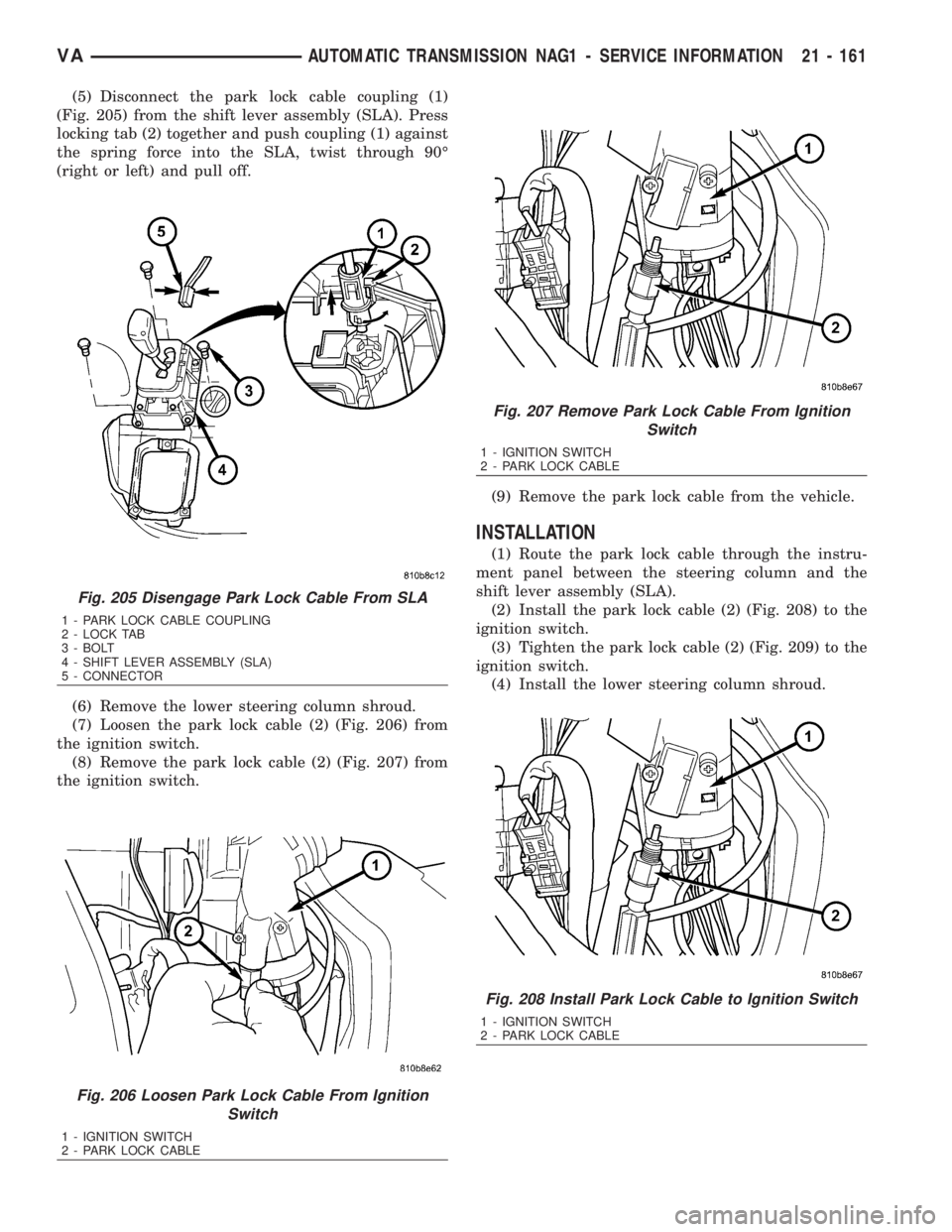
(5) Disconnect the park lock cable coupling (1)
(Fig. 205) from the shift lever assembly (SLA). Press
locking tab (2) together and push coupling (1) against
the spring force into the SLA, twist through 90É
(right or left) and pull off.
(6) Remove the lower steering column shroud.
(7) Loosen the park lock cable (2) (Fig. 206) from
the ignition switch.
(8) Remove the park lock cable (2) (Fig. 207) from
the ignition switch.(9) Remove the park lock cable from the vehicle.
INSTALLATION
(1) Route the park lock cable through the instru-
ment panel between the steering column and the
shift lever assembly (SLA).
(2) Install the park lock cable (2) (Fig. 208) to the
ignition switch.
(3) Tighten the park lock cable (2) (Fig. 209) to the
ignition switch.
(4) Install the lower steering column shroud.
Fig. 205 Disengage Park Lock Cable From SLA
1 - PARK LOCK CABLE COUPLING
2 - LOCK TAB
3 - BOLT
4 - SHIFT LEVER ASSEMBLY (SLA)
5 - CONNECTOR
Fig. 206 Loosen Park Lock Cable From Ignition
Switch
1 - IGNITION SWITCH
2 - PARK LOCK CABLE
Fig. 207 Remove Park Lock Cable From Ignition
Switch
1 - IGNITION SWITCH
2 - PARK LOCK CABLE
Fig. 208 Install Park Lock Cable to Ignition Switch
1 - IGNITION SWITCH
2 - PARK LOCK CABLE
VAAUTOMATIC TRANSMISSION NAG1 - SERVICE INFORMATION 21 - 161
Page 1905 of 2305
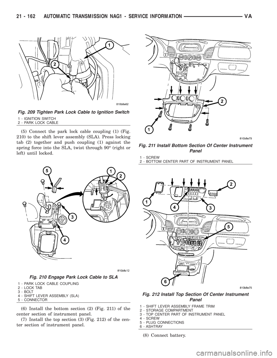
(5) Connect the park lock cable coupling (1) (Fig.
210) to the shift lever assembly (SLA). Press locking
tab (2) together and push coupling (1) against the
spring force into the SLA, twist through 90É (right or
left) until locked.
(6) Install the bottom section (2) (Fig. 211) of the
center section of instrument panel.
(7) Install the top section (3) (Fig. 212) of the cen-
ter section of instrument panel.
(8) Connect battery.
Fig. 209 Tighten Park Lock Cable to Ignition Switch
1 - IGNITION SWITCH
2 - PARK LOCK CABLE
Fig. 210 Engage Park Lock Cable to SLA
1 - PARK LOCK CABLE COUPLING
2 - LOCK TAB
3 - BOLT
4 - SHIFT LEVER ASSEMBLY (SLA)
5 - CONNECTOR
Fig. 211 Install Bottom Section Of Center Instrument
Panel
1 - SCREW
2 - BOTTOM CENTER PART OF INSTRUMENT PANEL
Fig. 212 Install Top Section Of Center Instrument
Panel
1 - SHIFT LEVER ASSEMBLY FRAME TRIM
2 - STORAGE COMPARTMENT
3 - TOP CENTER PART OF INSTRUMENT PANEL
4 - SCREW
5 - PLUG CONNECTIONS
6 - ASHTRAY
21 - 162 AUTOMATIC TRANSMISSION NAG1 - SERVICE INFORMATIONVA
Page 1911 of 2305
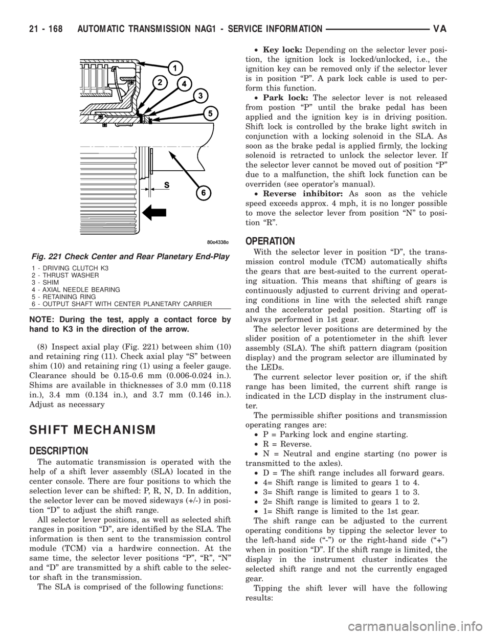
NOTE: During the test, apply a contact force by
hand to K3 in the direction of the arrow.
(8) Inspect axial play (Fig. 221) between shim (10)
and retaining ring (11). Check axial play ªSº between
shim (10) and retaining ring (1) using a feeler gauge.
Clearance should be 0.15-0.6 mm (0.006-0.024 in.).
Shims are available in thicknesses of 3.0 mm (0.118
in.), 3.4 mm (0.134 in.), and 3.7 mm (0.146 in.).
Adjust as necessary
SHIFT MECHANISM
DESCRIPTION
The automatic transmission is operated with the
help of a shift lever assembly (SLA) located in the
center console. There are four positions to which the
selection lever can be shifted: P, R, N, D. In addition,
the selector lever can be moved sideways (+/-) in posi-
tion ªDº to adjust the shift range.
All selector lever positions, as well as selected shift
ranges in position ªDº, are identified by the SLA. The
information is then sent to the transmission control
module (TCM) via a hardwire connection. At the
same time, the selector lever positions ªPº, ªRº, ªNº
and ªDº are transmitted by a shift cable to the selec-
tor shaft in the transmission.
The SLA is comprised of the following functions:²Key lock:Depending on the selector lever posi-
tion, the ignition lock is locked/unlocked, i.e., the
ignition key can be removed only if the selector lever
is in position ªPº. A park lock cable is used to per-
form this function.
²Park lock:The selector lever is not released
from postion ªPº until the brake pedal has been
applied and the ignition key is in driving position.
Shift lock is controlled by the brake light switch in
conjunction with a locking solenoid in the SLA. As
soon as the brake pedal is applied firmly, the locking
solenoid is retracted to unlock the selector lever. If
the selector lever cannot be moved out of position ªPº
due to a malfunction, the shift lock function can be
overriden (see operator's manual).
²Reverse inhibitor:As soon as the vehicle
speed exceeds approx. 4 mph, it is no longer possible
to move the selector lever from position ªNº to posi-
tion ªRº.
OPERATION
With the selector lever in position ªDº, the trans-
mission control module (TCM) automatically shifts
the gears that are best-suited to the current operat-
ing situation. This means that shifting of gears is
continuously adjusted to current driving and operat-
ing conditions in line with the selected shift range
and the accelerator pedal position. Starting off is
always performed in 1st gear.
The selector lever positions are determined by the
slider position of a potentiometer in the shift lever
assembly (SLA). The shift pattern diagram (position
display) and the program selector are illuminated by
the LEDs.
The current selector lever position or, if the shift
range has been limited, the current shift range is
indicated in the LCD display in the instrument clus-
ter.
The permissible shifter positions and transmission
operating ranges are:
²P = Parking lock and engine starting.
²R = Reverse.
²N = Neutral and engine starting (no power is
transmitted to the axles).
²D = The shift range includes all forward gears.
²4= Shift range is limited to gears 1 to 4.
²3= Shift range is limited to gears 1 to 3.
²2= Shift range is limited to gears 1 to 2.
²1= Shift range is limited to the 1st gear.
The shift range can be adjusted to the current
operating conditions by tipping the selector lever to
the left-hand side (ª-º) or the right-hand side (ª+º)
when in position ªDº. If the shift range is limited, the
display in the instrument cluster indicates the
selected shift range and not the currently engaged
gear.
Tipping the shift lever will have the following
results:Fig. 221 Check Center and Rear Planetary End-Play
1 - DRIVING CLUTCH K3
2 - THRUST WASHER
3 - SHIM
4 - AXIAL NEEDLE BEARING
5 - RETAINING RING
6 - OUTPUT SHAFT WITH CENTER PLANETARY CARRIER
21 - 168 AUTOMATIC TRANSMISSION NAG1 - SERVICE INFORMATIONVA
Page 1914 of 2305
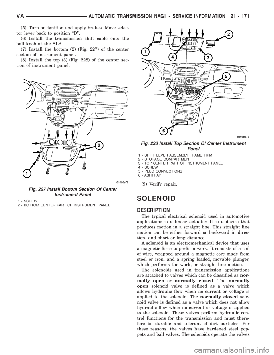
(5) Turn on ignition and apply brakes. Move selec-
tor lever back to position ªDº.
(6) Install the transmission shift cable onto the
ball knob at the SLA.
(7) Install the bottom (2) (Fig. 227) of the center
section of instrument panel.
(8) Install the top (3) (Fig. 228) of the center sec-
tion of instrument panel.
(9) Verify repair.
SOLENOID
DESCRIPTION
The typical electrical solenoid used in automotive
applications is a linear actuator. It is a device that
produces motion in a straight line. This straight line
motion can be either forward or backward in direc-
tion, and short or long distance.
A solenoid is an electromechanical device that uses
a magnetic force to perform work. It consists of a coil
of wire, wrapped around a magnetic core made from
steel or iron, and a spring loaded, movable plunger,
which performs the work, or straight line motion.
The solenoids used in transmission applications
are attached to valves which can be classified asnor-
mally openornormally closed. Thenormally
opensolenoid valve is defined as a valve which
allows hydraulic flow when no current or voltage is
applied to the solenoid. Thenormally closedsole-
noid valve is defined as a valve which does not allow
hydraulic flow when no current or voltage is applied
to the solenoid. These valves perform hydraulic con-
trol functions for the transmission and must there-
fore be durable and tolerant of dirt particles. For
these reasons, the valves have hardened steel pop-
pets and ball valves. The solenoids operate the valves
Fig. 227 Install Bottom Section Of Center
Instrument Panel
1 - SCREW
2 - BOTTOM CENTER PART OF INSTRUMENT PANEL
Fig. 228 Install Top Section Of Center Instrument
Panel
1 - SHIFT LEVER ASSEMBLY FRAME TRIM
2 - STORAGE COMPARTMENT
3 - TOP CENTER PART OF INSTRUMENT PANEL
4 - SCREW
5 - PLUG CONNECTIONS
6 - ASHTRAY
VAAUTOMATIC TRANSMISSION NAG1 - SERVICE INFORMATION 21 - 171
Page 1944 of 2305
BODY
TABLE OF CONTENTS
page page
BODY
WARNING
SAFETY PRECAUTIONS AND WARNINGS . . . 1
DIAGNOSIS AND TESTING
DIAGNOSIS AND TESTING - WATER LEAKS . 1
DIAGNOSIS AND TESTING - WIND NOISE . . . 2
STANDARD PROCEDURE
STANDARD PROCEDURE - PLASTIC BODY
PANEL REPAIR........................3
STANDARD PROCEDURE - BUZZ, SQUEAK
& RATTLE...........................10
SPECIFICATIONS.......................11DOOR - FRONT..........................13
DOORS - REAR..........................23
DOORS - SLIDING........................35
EXTERIOR..............................48
HOOD.................................51
INSTRUMENT PANEL.....................55
INTERIOR..............................70
PAINT.................................77
SEATS.................................79
STATIONARY GLASS.....................84
WEATHERSTRIP/SEALS...................90
BODY STRUCTURE.......................91
BODY
WARNING
SAFETY PRECAUTIONS AND WARNINGS
WARNING: USE AN OSHA APPROVED BREATHING
FILTER WHEN SPRAYING PAINT OR SOLVENTS IN
A CONFINED AREA. PERSONAL INJURY CAN
RESULT.
²AVOID PROLONGED SKIN CONTACT WITH
PETROLEUM OR ALCOHOL ± BASED CLEANING
SOLVENTS. PERSONAL INJURY CAN RESULT.
²DO NOT STAND UNDER A HOISTED VEHICLE
THAT IS NOT PROPERLY SUPPORTED ON SAFETY
STANDS. PERSONAL INJURY CAN RESULT.
CAUTION: When holes must be drilled or punched
in an inner body panel, verify depth of space to the
outer body panel, electrical wiring, or other compo-
nents. Damage to vehicle can result.
²Do not weld exterior panels unless combustible
material on the interior of vehicle is removed from
the repair area. Fire or hazardous conditions, can
result.
²Always have a fire extinguisher ready for use
when welding.
²Disconnect the negative (-) cable clamp from
the battery when servicing electrical components
that are live when the ignition is OFF. Damage to
electrical system can result.
²Do not use abrasive chemicals or compounds
on painted surfaces. Damage to finish can result.²Do not use harsh alkaline based cleaning sol-
vents on painted or upholstered surfaces. Damage
to finish or color can result.
²Do not hammer or pound on plastic trim panel
when servicing interior trim. Plastic panels can
break.DIAGNOSIS AND TESTING
DIAGNOSIS AND TESTING - WATER LEAKS
Water leaks can be caused by poor sealing,
improper body component alignment, body seam
porosity, missing plugs, or blocked drain holes. Cen-
trifugal and gravitational force can cause water to
drip from a location away from the actual leak point,
making leak detection difficult. All body sealing
points should be water tight in normal wet-driving
conditions. Water flowing downward from the front of
the vehicle should not enter the passenger or luggage
compartment. Moving sealing surfaces will not
always seal water tight under all conditions. At
times, side glass or door seals will allow water to
enter the passenger compartment during high pres-
sure washing or hard driving rain (severe) condi-
tions. Overcompensating on door or glass
adjustments to stop a water leak that occurs under
severe conditions can cause premature seal wear and
excessive closing or latching effort. After completing
a repair, water test vehicle to verify leak has stopped
before returning vehicle to use.
VISUAL INSPECTION BEFORE WATER LEAK TESTS
Verify that floor and body plugs are in place, body
drains are clear, and body components are properly
VABODY 23 - 1