2006 MERCEDES-BENZ SPRINTER ignition
[x] Cancel search: ignitionPage 1656 of 2305
TIMING CHAIN TENSIONER
REMOVAL
(1) Disconnect negative battery cable.
CAUTION: Rotate engine at crankshaft only. DO
NOT rotate the engine with the bolt of the camshaft
sprocket. DO NOT rotate the engine counter clock-
wise.
NOTE: Markings on the camshaft and camshaft
bearing cap must be aligned.
(2) Position piston of number 1 cylinder to ignition
TDC.
(3) Remove intake air duct.
(4) Remove accessory drive belt and idler pulley
above generator (Refer to 7 - COOLING/ACCES-
SORY DRIVE/DRIVE BELTS - REMOVAL).
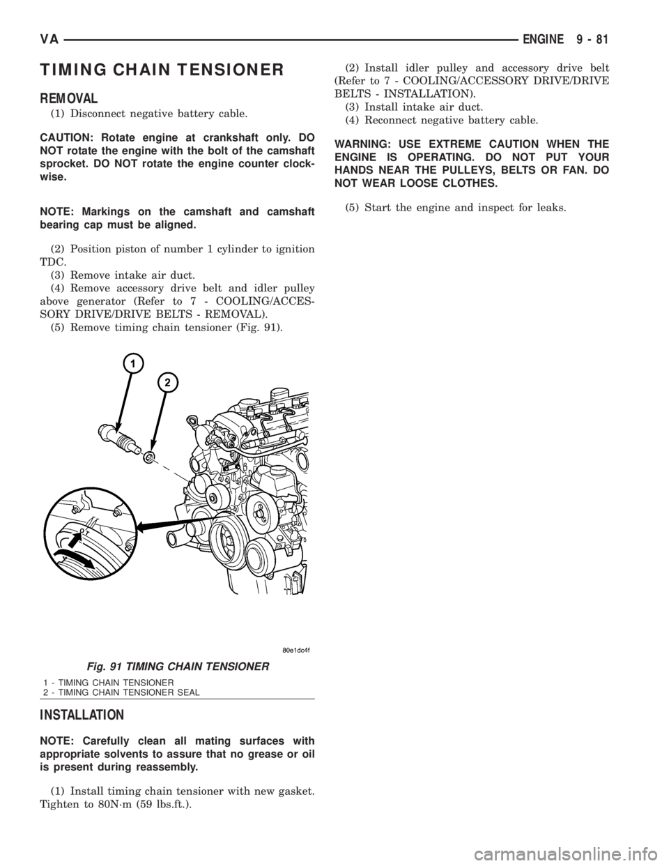
(5) Remove timing chain tensioner (Fig. 91).
INSTALLATION
NOTE: Carefully clean all mating surfaces with
appropriate solvents to assure that no grease or oil
is present during reassembly.
(1) Install timing chain tensioner with new gasket.
Tighten to 80N´m (59 lbs.ft.).(2) Install idler pulley and accessory drive belt
(Refer to 7 - COOLING/ACCESSORY DRIVE/DRIVE
BELTS - INSTALLATION).
(3) Install intake air duct.
(4) Reconnect negative battery cable.
WARNING: USE EXTREME CAUTION WHEN THE
ENGINE IS OPERATING. DO NOT PUT YOUR
HANDS NEAR THE PULLEYS, BELTS OR FAN. DO
NOT WEAR LOOSE CLOTHES.
(5) Start the engine and inspect for leaks.
Fig. 91 TIMING CHAIN TENSIONER
1 - TIMING CHAIN TENSIONER
2 - TIMING CHAIN TENSIONER SEAL
VAENGINE 9 - 81
Page 1683 of 2305
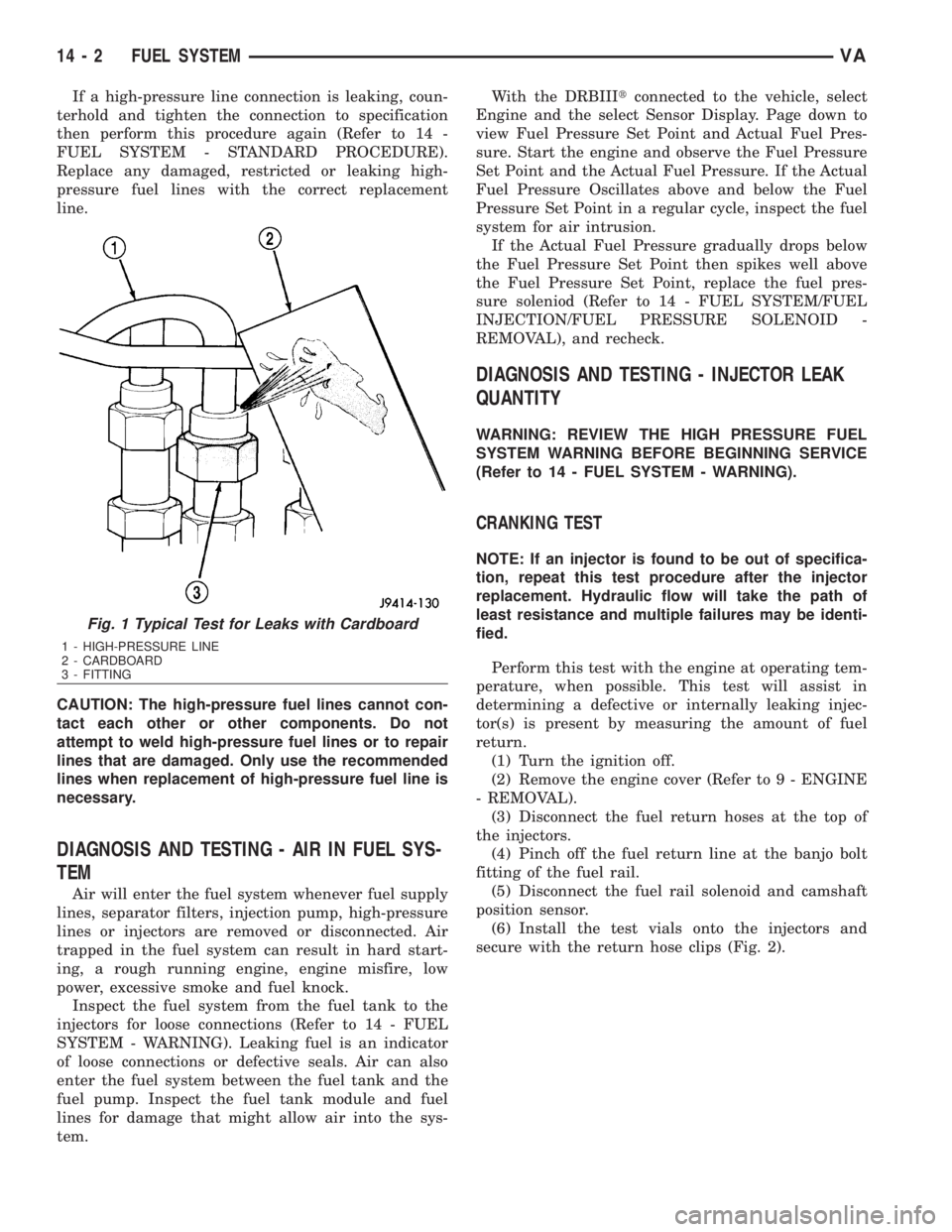
If a high-pressure line connection is leaking, coun-
terhold and tighten the connection to specification
then perform this procedure again (Refer to 14 -
FUEL SYSTEM - STANDARD PROCEDURE).
Replace any damaged, restricted or leaking high-
pressure fuel lines with the correct replacement
line.
CAUTION: The high-pressure fuel lines cannot con-
tact each other or other components. Do not
attempt to weld high-pressure fuel lines or to repair
lines that are damaged. Only use the recommended
lines when replacement of high-pressure fuel line is
necessary.
DIAGNOSIS AND TESTING - AIR IN FUEL SYS-
TEM
Air will enter the fuel system whenever fuel supply
lines, separator filters, injection pump, high-pressure
lines or injectors are removed or disconnected. Air
trapped in the fuel system can result in hard start-
ing, a rough running engine, engine misfire, low
power, excessive smoke and fuel knock.
Inspect the fuel system from the fuel tank to the
injectors for loose connections (Refer to 14 - FUEL
SYSTEM - WARNING). Leaking fuel is an indicator
of loose connections or defective seals. Air can also
enter the fuel system between the fuel tank and the
fuel pump. Inspect the fuel tank module and fuel
lines for damage that might allow air into the sys-
tem.With the DRBIIItconnected to the vehicle, select
Engine and the select Sensor Display. Page down to
view Fuel Pressure Set Point and Actual Fuel Pres-
sure. Start the engine and observe the Fuel Pressure
Set Point and the Actual Fuel Pressure. If the Actual
Fuel Pressure Oscillates above and below the Fuel
Pressure Set Point in a regular cycle, inspect the fuel
system for air intrusion.
If the Actual Fuel Pressure gradually drops below
the Fuel Pressure Set Point then spikes well above
the Fuel Pressure Set Point, replace the fuel pres-
sure soleniod (Refer to 14 - FUEL SYSTEM/FUEL
INJECTION/FUEL PRESSURE SOLENOID -
REMOVAL), and recheck.
DIAGNOSIS AND TESTING - INJECTOR LEAK
QUANTITY
WARNING: REVIEW THE HIGH PRESSURE FUEL
SYSTEM WARNING BEFORE BEGINNING SERVICE
(Refer to 14 - FUEL SYSTEM - WARNING).
CRANKING TEST
NOTE: If an injector is found to be out of specifica-
tion, repeat this test procedure after the injector
replacement. Hydraulic flow will take the path of
least resistance and multiple failures may be identi-
fied.
Perform this test with the engine at operating tem-
perature, when possible. This test will assist in
determining a defective or internally leaking injec-
tor(s) is present by measuring the amount of fuel
return.
(1) Turn the ignition off.
(2) Remove the engine cover (Refer to 9 - ENGINE
- REMOVAL).
(3) Disconnect the fuel return hoses at the top of
the injectors.
(4) Pinch off the fuel return line at the banjo bolt
fitting of the fuel rail.
(5) Disconnect the fuel rail solenoid and camshaft
position sensor.
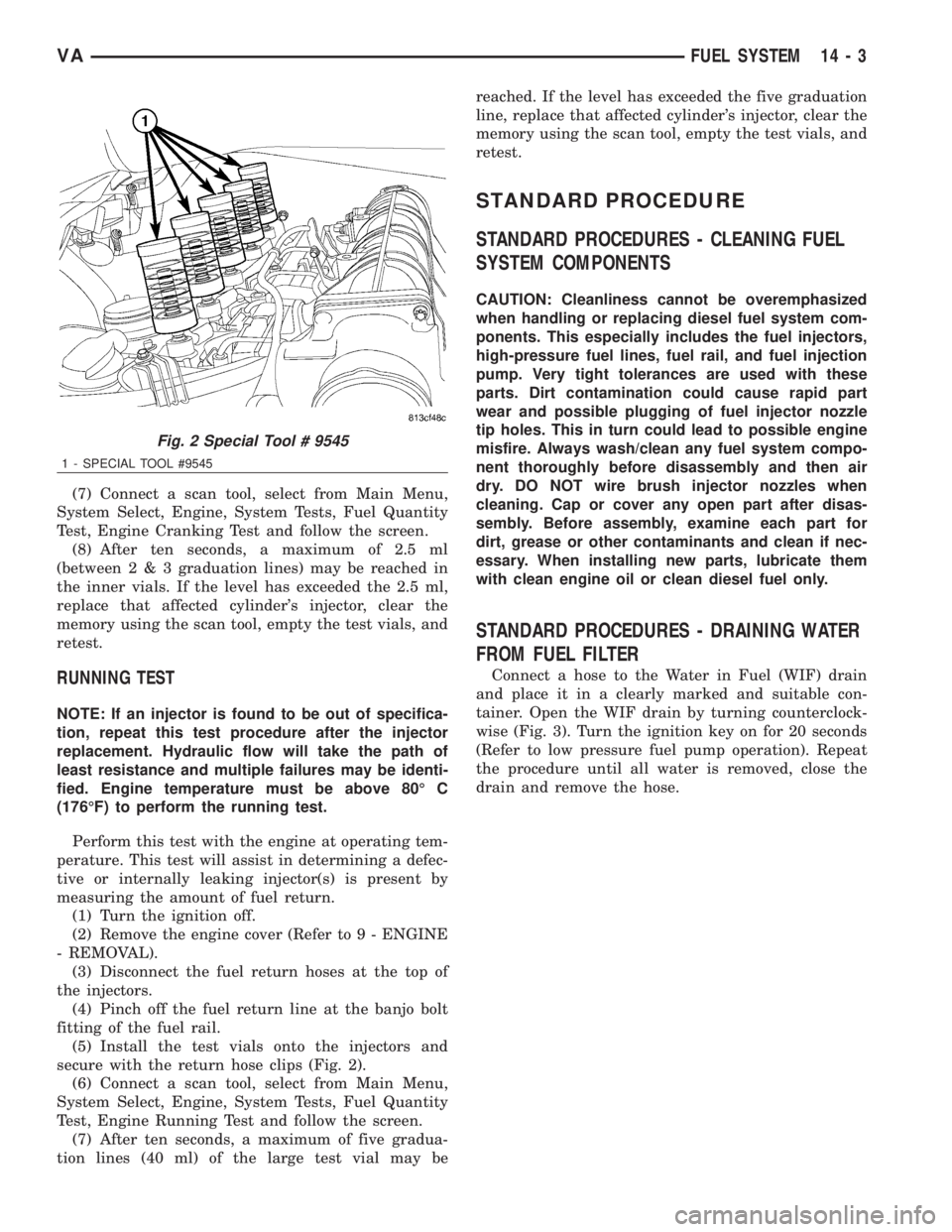
(6) Install the test vials onto the injectors and
secure with the return hose clips (Fig. 2).
Fig. 1 Typical Test for Leaks with Cardboard
1 - HIGH-PRESSURE LINE
2 - CARDBOARD
3 - FITTING
14 - 2 FUEL SYSTEMVA
Page 1684 of 2305
(7) Connect a scan tool, select from Main Menu,
System Select, Engine, System Tests, Fuel Quantity
Test, Engine Cranking Test and follow the screen.
(8) After ten seconds, a maximum of 2.5 ml
(between2&3graduation lines) may be reached in
the inner vials. If the level has exceeded the 2.5 ml,
replace that affected cylinder's injector, clear the
memory using the scan tool, empty the test vials, and
retest.
RUNNING TEST
NOTE: If an injector is found to be out of specifica-
tion, repeat this test procedure after the injector
replacement. Hydraulic flow will take the path of
least resistance and multiple failures may be identi-
fied. Engine temperature must be above 80É C
(176ÉF) to perform the running test.
Perform this test with the engine at operating tem-
perature. This test will assist in determining a defec-
tive or internally leaking injector(s) is present by
measuring the amount of fuel return.
(1) Turn the ignition off.
(2) Remove the engine cover (Refer to 9 - ENGINE
- REMOVAL).
(3) Disconnect the fuel return hoses at the top of
the injectors.
(4) Pinch off the fuel return line at the banjo bolt
fitting of the fuel rail.
(5) Install the test vials onto the injectors and
secure with the return hose clips (Fig. 2).
(6) Connect a scan tool, select from Main Menu,
System Select, Engine, System Tests, Fuel Quantity
Test, Engine Running Test and follow the screen.
(7) After ten seconds, a maximum of five gradua-
tion lines (40 ml) of the large test vial may bereached. If the level has exceeded the five graduation
line, replace that affected cylinder's injector, clear the
memory using the scan tool, empty the test vials, and
retest.
STANDARD PROCEDURE
STANDARD PROCEDURES - CLEANING FUEL
SYSTEM COMPONENTS
CAUTION: Cleanliness cannot be overemphasized
when handling or replacing diesel fuel system com-
ponents. This especially includes the fuel injectors,
high-pressure fuel lines, fuel rail, and fuel injection
pump. Very tight tolerances are used with these
parts. Dirt contamination could cause rapid part
wear and possible plugging of fuel injector nozzle
tip holes. This in turn could lead to possible engine
misfire. Always wash/clean any fuel system compo-
nent thoroughly before disassembly and then air
dry. DO NOT wire brush injector nozzles when
cleaning. Cap or cover any open part after disas-
sembly. Before assembly, examine each part for
dirt, grease or other contaminants and clean if nec-
essary. When installing new parts, lubricate them
with clean engine oil or clean diesel fuel only.
STANDARD PROCEDURES - DRAINING WATER
FROM FUEL FILTER
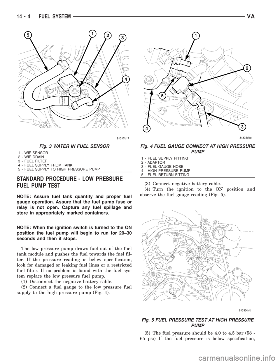
Connect a hose to the Water in Fuel (WIF) drain
and place it in a clearly marked and suitable con-
tainer. Open the WIF drain by turning counterclock-
wise (Fig. 3). Turn the ignition key on for 20 seconds
(Refer to low pressure fuel pump operation). Repeat
the procedure until all water is removed, close the
drain and remove the hose.
Fig. 2 Special Tool # 9545
1 - SPECIAL TOOL #9545
VAFUEL SYSTEM 14 - 3
Page 1685 of 2305
STANDARD PROCEDURE - LOW PRESSURE
FUEL PUMP TEST
NOTE: Assure fuel tank quantity and proper fuel
gauge operation. Assure that the fuel pump fuse or
relay is not open. Capture any fuel spillage and
store in appropriately marked containers.
NOTE: When the ignition switch is turned to the ON
position the fuel pump will begin to run for 20±30
seconds and then it stops.
The low pressure pump draws fuel out of the fuel
tank module and pushes the fuel towards the fuel fil-
ter. If the pressure reading is below specification,
look for damaged or leaking fuel lines or a restricted
fuel filter. If no problem is found with the fuel sys-
tem replace the low pressure fuel pump.
(1) Disconnect the negative battery cable.
(2) Connect a fuel gauge to the low pressure fuel
supply to the high pressure pump (Fig. 4).(3) Connect negative battery cable.
(4) Turn the ignition to the ON position and
observe the fuel gauge reading (Fig. 5).
(5) The fuel pressure should be 4.0 to 4.5 bar (58 -
65 psi) If the fuel pressure is below specification,
Fig. 3 WATER IN FUEL SENSOR
1 - WIF SENSOR
2 - WIF DRAIN
3 - FUEL FILTER
4 - FUEL SUPPLY FROM TANK
5 - FUEL SUPPLY TO HIGH PRESSURE PUMP
Fig. 4 FUEL GAUGE CONNECT AT HIGH PRESSURE
PUMP
1 - FUEL SUPPLY FITTING
2 - ADAPTOR
3 - FUEL GAUGE HOSE
4 - HIGH PRESSURE PUMP
5 - FUEL RETURN FITTING
Fig. 5 FUEL PRESSURE TEST AT HIGH PRESSURE
PUMP
14 - 4 FUEL SYSTEMVA
Page 1692 of 2305
INSTALLATION
WARNING: NO SPARKS, OPEN FLAMES OR SMOK-
ING. RISK OF POISONING FROM INHALING AND
SWALLOWING FUEL. RISK OF INJURY TO EYES
AND SKIN FROM CONTACT WITH FUEL. POUR
FUELS ONLY INTO SUITABLE AND APPROPRI-
ATELY MARKED CONTAINERS. WEAR PROTECTIVE
CLOTHING.
CAUTION: DO NOT bend, twist or cut the fuel hose
clamps. The fuel hose clamps through out the fuel
system are reusable when using special tool #9539.
Orginal clamps must be used when servicing the
fuel system.
NOTE: Capture any fuel spillage and dispose of in
appropriately marked container.
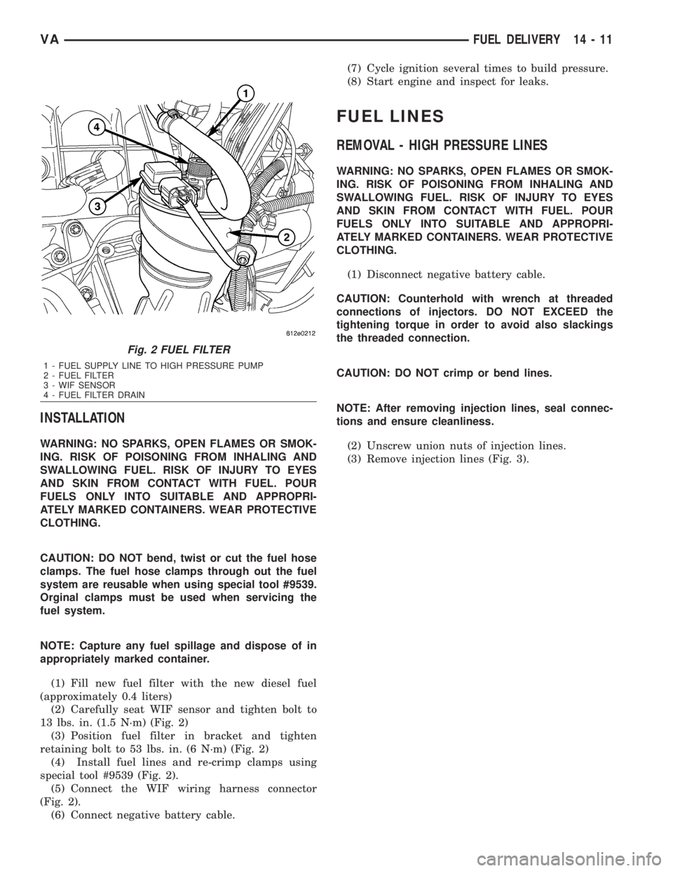
(1) Fill new fuel filter with the new diesel fuel
(approximately 0.4 liters)
(2) Carefully seat WIF sensor and tighten bolt to
13 lbs. in. (1.5 N´m) (Fig. 2)
(3) Position fuel filter in bracket and tighten
retaining bolt to 53 lbs. in. (6 N´m) (Fig. 2)
(4) Install fuel lines and re-crimp clamps using
special tool #9539 (Fig. 2).
(5) Connect the WIF wiring harness connector
(Fig. 2).
(6) Connect negative battery cable.(7) Cycle ignition several times to build pressure.
(8) Start engine and inspect for leaks.
FUEL LINES
REMOVAL - HIGH PRESSURE LINES
WARNING: NO SPARKS, OPEN FLAMES OR SMOK-
ING. RISK OF POISONING FROM INHALING AND
SWALLOWING FUEL. RISK OF INJURY TO EYES
AND SKIN FROM CONTACT WITH FUEL. POUR
FUELS ONLY INTO SUITABLE AND APPROPRI-
ATELY MARKED CONTAINERS. WEAR PROTECTIVE
CLOTHING.
(1) Disconnect negative battery cable.
CAUTION: Counterhold with wrench at threaded
connections of injectors. DO NOT EXCEED the
tightening torque in order to avoid also slackings
the threaded connection.
CAUTION: DO NOT crimp or bend lines.
NOTE: After removing injection lines, seal connec-
tions and ensure cleanliness.
(2) Unscrew union nuts of injection lines.
(3) Remove injection lines (Fig. 3).
Fig. 2 FUEL FILTER
1 - FUEL SUPPLY LINE TO HIGH PRESSURE PUMP
2 - FUEL FILTER
3 - WIF SENSOR
4 - FUEL FILTER DRAIN
VAFUEL DELIVERY 14 - 11
Page 1697 of 2305
OPERATION - LOW PRESSURE PUMP
When the ignition switch is on, fused battery posi-
tive voltage is supplied to the electric lift pump,
which will run for 20±30 seconds and then stop. If
the engine is cranked, the pump will begin running
immediately supplying fuel through fuel filter and
onto the high pressure pump. The lift pump and low
pressure fuel circuit operate at a pressure between
3.8 -5.5 bar (55 - 80 psi.).
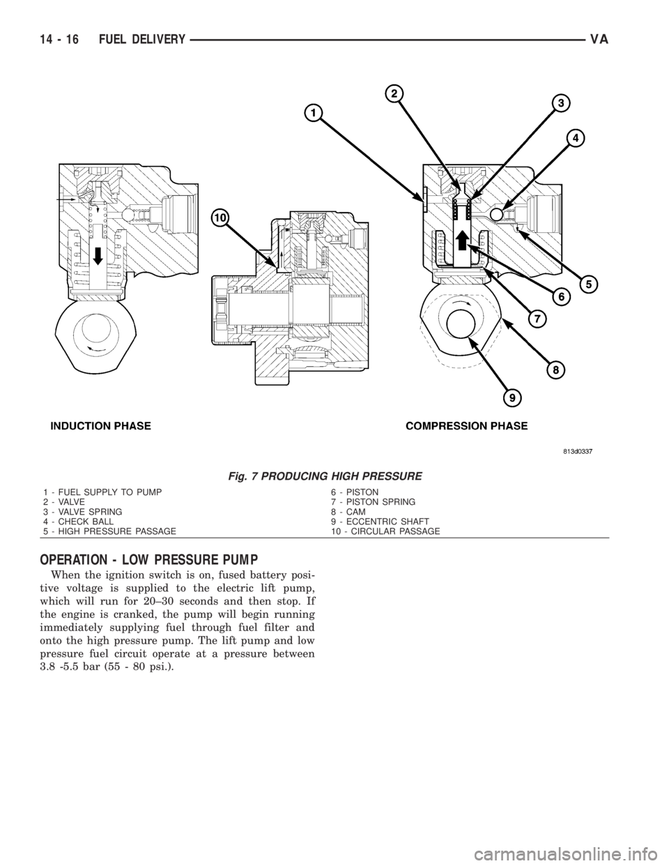
Fig. 7 PRODUCING HIGH PRESSURE
1 - FUEL SUPPLY TO PUMP 6 - PISTON
2 - VALVE 7 - PISTON SPRING
3 - VALVE SPRING 8 - CAM
4 - CHECK BALL 9 - ECCENTRIC SHAFT
5 - HIGH PRESSURE PASSAGE 10 - CIRCULAR PASSAGE
14 - 16 FUEL DELIVERYVA
Page 1715 of 2305
is synchronized by means of the camshaft signal and
the crankshaft signal.
OPERATION
On the camshaft sensor's signal line, a high signal
correspons to a voltage of 0-5V. If the segment
machined into the exhaust camshaft sprocket is posi-
tioned opposite the camshaft sensor, the camshaft
signal is low, approximately 0V. This signal is used
by the engine control module (ECM) for detecting
ignition TDC of cylinder 1 as the engine rotates. If no
signal is supplied by the camshaft position sensor,
the vehicle will not start because cylinder order can
not be detected.
REMOVAL
(1) Disconnect negative battery cable.
(2) Remove engine cover
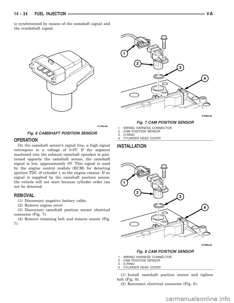
(3) Disconnect camshaft position sensor electrical
connector (Fig. 7).
(4) Remove retaining bolt and remove sensor (Fig.
7).
INSTALLATION
(1) Install camshaft position sensor and tighten
bolt (Fig. 8).
(2) Reconnect electrical connector (Fig. 8).
Fig. 6 CAMSHAFT POSITION SENSOR
Fig. 7 CAM POSITION SENSOR
1 - WIRING HARNESS CONNECTOR
2 - CAM POSITION SENSOR
3 - O-RING
4 - CYLINDER HEAD COVER
Fig. 8 CAM POSITION SENSOR
1 - WIRING HARNESS CONNECTOR
2 - CAM POSITION SENSOR
3 - O-RING
4 - CYLINDER HEAD COVER
14 - 34 FUEL INJECTIONVA
Page 1719 of 2305
INJECTOR CLASSIFICATION PROCEDURE
(1) Turn ignition switch ªONº.
(2) Using a DRB IIItand select ENGINE then
MISCELLANEOUS.
(3) Select LEARN INJECTORS.
(4) Using the up and down arrows, scroll to the
appropriate injector.
(5) Using the right and left arrows, set injector to
proper classification.
(6) Once injectors are classified, cycle ignition to
complete.
CLEANING FUEL INJECTORS
NOTE: Before cleaning the injector recesses, seal
the injector holes in the injector recesses with the
appropriate pin to prevent debris from falling into
the recesses and entering the motor.
(1) Seal the injector holes inside the cylinder head
recesses.
(2) Wipe out injector recesses with a non-woven
cloth, then clean with a cylinder brush.
(3) Clean the bottom of the cylinder recess with a
round brush.
(4) Blow out the recess and clean again with a
non-woven cloth and cover over.
(5) Perform these steps for each injector recess.
NOTE: DO NOT clean the tip of the injector with a
wire brush. Use a non - woven cloth.
(6) Clean injector body with a wire brush.
(7) Clean injector tips with a non-woven cloth.
NOTE: Do Not apply antiseize lubricant to the injec-
tor nozzle area.
(8) Grease injector body with anti seize lubricant.
NOTE: Always replace the seals that seal off the
injectors at the cylinder head to the combustion
chamber and replace the retaining screws.
REMOVAL
WARNING: NO SPARKS, OPEN FLAMES OR SMOK-
ING. RISK OF POISONING FROM INHALING AND
SWALLOWING FUEL. RISK OF INJURY TO EYES
AND SKIN FROM CONTACT WITH FUEL. POUR
FUELS ONLY INTO SUITABLE AND APPROPRI-
ATELY MARKED CONTAINERS. WEAR PROTECTIVE
CLOTHING.
NOTE: When removing injectors, the seal rings and
retaining stretch bolts must always be replaced.
Coat the injector body with the anti-seize com-pound before installing. Keep lubricant away from
the injector nozzle.
(1) Disconnect negative battery cable.
(2) Remove engine cover (Refer to 9 - ENGINE -
REMOVAL).
(3) Remove the fuel return hose locking clamps at
the injector and remove return hose.
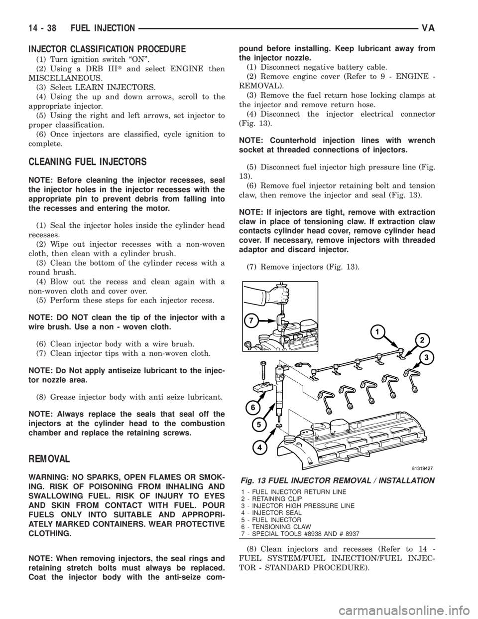
(4) Disconnect the injector electrical connector
(Fig. 13).
NOTE: Counterhold injection lines with wrench
socket at threaded connections of injectors.
(5) Disconnect fuel injector high pressure line (Fig.
13).
(6) Remove fuel injector retaining bolt and tension
claw, then remove the injector and seal (Fig. 13).
NOTE: If injectors are tight, remove with extraction
claw in place of tensioning claw. If extraction claw
contacts cylinder head cover, remove cylinder head
cover. If necessary, remove injectors with threaded
adaptor and discard injector.
(7) Remove injectors (Fig. 13).
(8) Clean injectors and recesses (Refer to 14 -
FUEL SYSTEM/FUEL INJECTION/FUEL INJEC-
TOR - STANDARD PROCEDURE).Fig. 13 FUEL INJECTOR REMOVAL / INSTALLATION
1 - FUEL INJECTOR RETURN LINE
2 - RETAINING CLIP
3 - INJECTOR HIGH PRESSURE LINE
4 - INJECTOR SEAL
5 - FUEL INJECTOR
6 - TENSIONING CLAW
7 - SPECIAL TOOLS #8938 AND # 8937
14 - 38 FUEL INJECTIONVA