Page 2176 of 2305

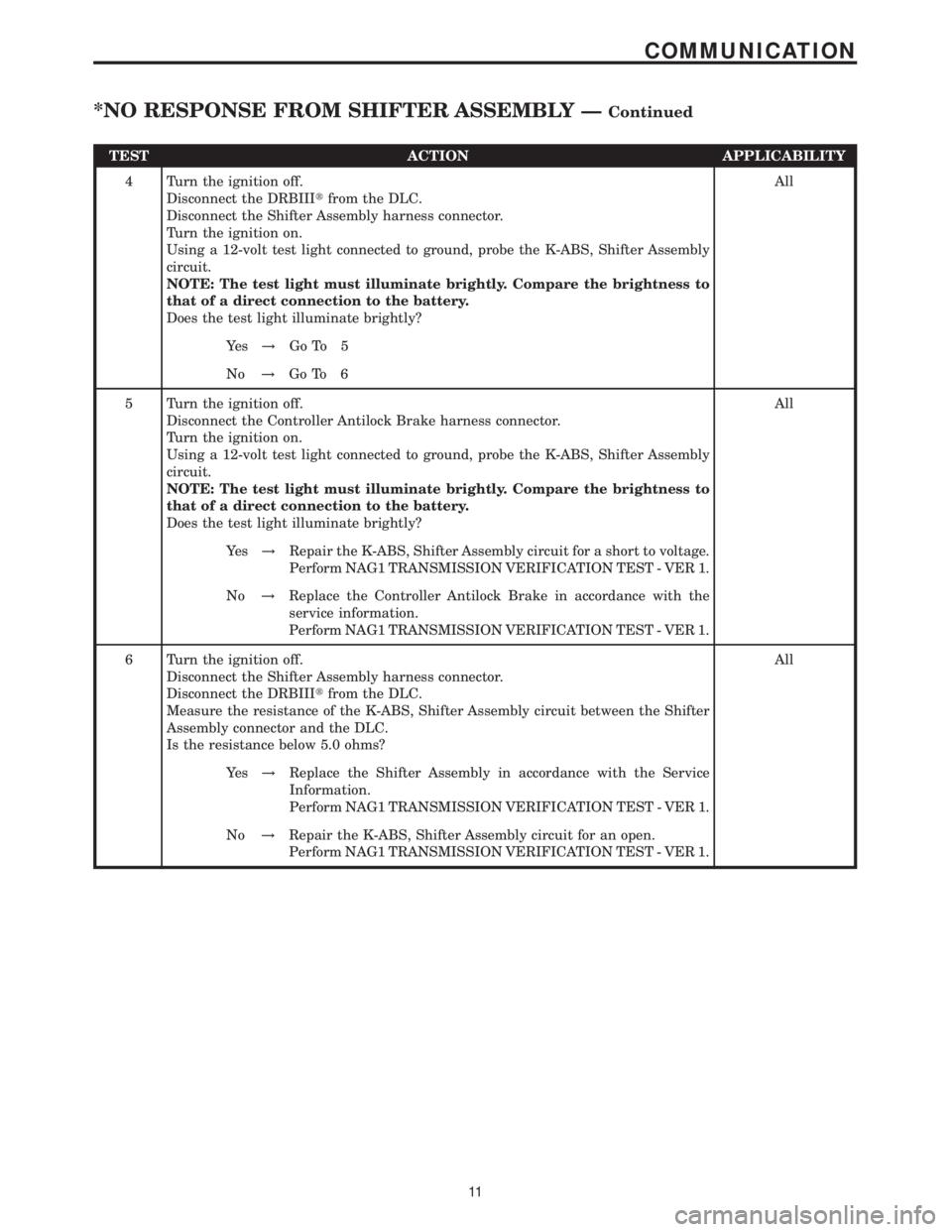
TEST ACTION APPLICABILITY
4 Turn the ignition off.
Disconnect the DRBIIItfrom the DLC.
Disconnect the Shifter Assembly harness connector.
Turn the ignition on.
Using a 12-volt test light connected to ground, probe the K-ABS, Shifter Assembly
circuit.
NOTE: The test light must illuminate brightly. Compare the brightness to
that of a direct connection to the battery.
Does the test light illuminate brightly?All
Ye s!Go To 5
No!Go To 6
5 Turn the ignition off.
Disconnect the Controller Antilock Brake harness connector.
Turn the ignition on.
Using a 12-volt test light connected to ground, probe the K-ABS, Shifter Assembly
circuit.
NOTE: The test light must illuminate brightly. Compare the brightness to
that of a direct connection to the battery.
Does the test light illuminate brightly?All
Ye s!Repair the K-ABS, Shifter Assembly circuit for a short to voltage.
Perform NAG1 TRANSMISSION VERIFICATION TEST - VER 1.
No!Replace the Controller Antilock Brake in accordance with the
service information.
Perform NAG1 TRANSMISSION VERIFICATION TEST - VER 1.
6 Turn the ignition off.
Disconnect the Shifter Assembly harness connector.
Disconnect the DRBIIItfrom the DLC.
Measure the resistance of the K-ABS, Shifter Assembly circuit between the Shifter
Assembly connector and the DLC.
Is the resistance below 5.0 ohms?All
Ye s!Replace the Shifter Assembly in accordance with the Service
Information.
Perform NAG1 TRANSMISSION VERIFICATION TEST - VER 1.
No!Repair the K-ABS, Shifter Assembly circuit for an open.
Perform NAG1 TRANSMISSION VERIFICATION TEST - VER 1.
11
COMMUNICATION
*NO RESPONSE FROM SHIFTER ASSEMBLY ÐContinued
Page 2177 of 2305

Symptom:
*NO RESPONSE FROM TRANSMISSION CONTROL MODULE
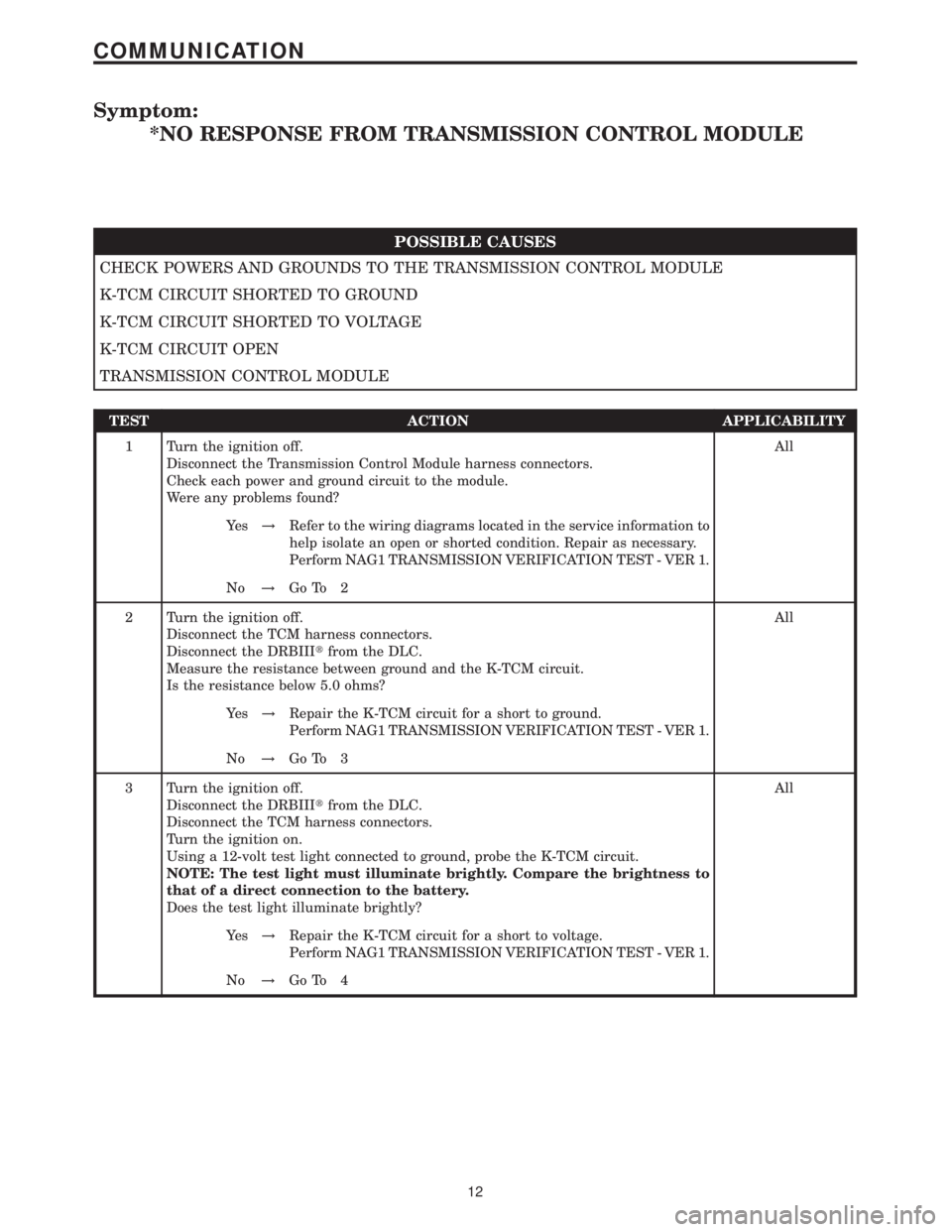
POSSIBLE CAUSES
CHECK POWERS AND GROUNDS TO THE TRANSMISSION CONTROL MODULE
K-TCM CIRCUIT SHORTED TO GROUND
K-TCM CIRCUIT SHORTED TO VOLTAGE
K-TCM CIRCUIT OPEN
TRANSMISSION CONTROL MODULE
TEST ACTION APPLICABILITY
1 Turn the ignition off.
Disconnect the Transmission Control Module harness connectors.
Check each power and ground circuit to the module.
Were any problems found?All
Ye s!Refer to the wiring diagrams located in the service information to
help isolate an open or shorted condition. Repair as necessary.
Perform NAG1 TRANSMISSION VERIFICATION TEST - VER 1.
No!Go To 2
2 Turn the ignition off.
Disconnect the TCM harness connectors.
Disconnect the DRBIIItfrom the DLC.
Measure the resistance between ground and the K-TCM circuit.
Is the resistance below 5.0 ohms?All
Ye s!Repair the K-TCM circuit for a short to ground.
Perform NAG1 TRANSMISSION VERIFICATION TEST - VER 1.
No!Go To 3
3 Turn the ignition off.
Disconnect the DRBIIItfrom the DLC.
Disconnect the TCM harness connectors.
Turn the ignition on.
Using a 12-volt test light connected to ground, probe the K-TCM circuit.
NOTE: The test light must illuminate brightly. Compare the brightness to
that of a direct connection to the battery.
Does the test light illuminate brightly?All
Ye s!Repair the K-TCM circuit for a short to voltage.
Perform NAG1 TRANSMISSION VERIFICATION TEST - VER 1.
No!Go To 4
12
COMMUNICATION
Page 2178 of 2305
TEST ACTION APPLICABILITY
4 Turn the ignition off.
Disconnect the TCM harness connectors.
Disconnect the DRBIIItfrom the DLC.
Measure the resistance of the K-TCM circuit between the TCM connector and the
DLC.
Is the resistance below 5.0 ohms?All
Ye s!Replace the Transmission Control Module in accordance with the
Service Information.
Perform NAG1 TRANSMISSION VERIFICATION TEST - VER 1.
No!Repair the K-TCM circuit for an open.
Perform NAG1 TRANSMISSION VERIFICATION TEST - VER 1.
13
COMMUNICATION
*NO RESPONSE FROM TRANSMISSION CONTROL MODULE ÐContinued
Page 2179 of 2305
Symptom:
BACKUP LAMP CKT SHORT TO GROUND
POSSIBLE CAUSES
BACKUP LAMP CIRCUIT SHORT TO GROUND
SHIFT LEVER ASSEMBLY
TEST ACTION APPLICABILITY
1 Turn the ignition off to the lock position.
Disconnect the Shift Lever Assembly harness connector.
Isolate the Backup Lamp circuit, remove the Backup Lamp bulbs.
NOTE: Check Backup Lamp bulbs and socket for a short or corrosion.
Measure the resistance between ground and the Backup Lamp circuit.
Is the resistance below 5.0 ohms?All
Ye s!Repair the Backup Lamp circuit for a short to ground.
No!Replace the Shift Lever Assembly per the Service Information.
14
SHIFT LEVER ASSEMBLY
Page 2180 of 2305

Symptom:
BACKUP LAMP CKT SHORT TO VOLTAGE OR OPEN
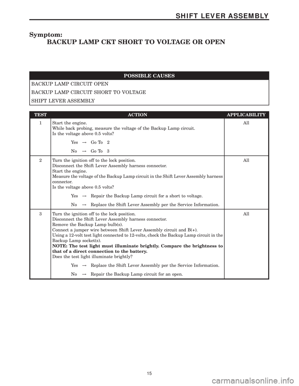
POSSIBLE CAUSES
BACKUP LAMP CIRCUIT OPEN
BACKUP LAMP CIRCUIT SHORT TO VOLTAGE
SHIFT LEVER ASSEMBLY
TEST ACTION APPLICABILITY
1 Start the engine.
While back probing, measure the voltage of the Backup Lamp circuit.
Is the voltage above 0.5 volts?All
Ye s!Go To 2
No!Go To 3
2 Turn the ignition off to the lock position.
Disconnect the Shift Lever Assembly harness connector.
Start the engine.
Measure the voltage of the Backup Lamp circuit in the Shift Lever Assembly harness
connector.
Is the voltage above 0.5 volts?All
Ye s!Repair the Backup Lamp circuit for a short to voltage.
No!Replace the Shift Lever Assembly per the Service Information.
3 Turn the ignition off to the lock position.
Disconnect the Shift Lever Assembly harness connector.
Remove the Backup Lamp bulb(s).
Connect a jumper wire between Shift Lever Assembly circuit and B(+).
Using a 12-volt test light connected to 12-volts, check the Backup Lamp circuit in the
Backup Lamp socket(s).
NOTE: The test light must illuminate brightly. Compare the brightness to
that of a direct connection to the battery.
Does the test light illuminate brightly?All
Ye s!Replace the Shift Lever Assembly per the Service Information.
No!Repair the Backup Lamp circuit for an open.
15
SHIFT LEVER ASSEMBLY
Page 2181 of 2305
Symptom:
BACKUP LAMP SUPPLY CIRCUIT OPEN
POSSIBLE CAUSES
FUSED IGNITION SWITCH OUTPUT OPEN
SHIFT LEVER ASSEMBLY
TEST ACTION APPLICABILITY
1 Turn the ignition off to the lock position.
Disconnect the Shift Lever Assembly harness connector.
Start the engine.
Using a 12-volt test light connected to ground, check the Fused Ignition Switch
Output circuit.
NOTE: The test light must illuminate brightly. Compare the brightness to
that of a direct connection to the battery.
Does the test light illuminate brightly?All
Ye s!Replace the Shift Lever Assembly per the Service Information.
No!Repair the Fused Ignition Switch Output circuit for an open. If
the fuse is open, make sure to check for a short to ground.
16
SHIFT LEVER ASSEMBLY
Page 2182 of 2305
Symptom:
CAN BUS CIRCUIT
POSSIBLE CAUSES
CAN COMMUNICATION FAILURE
CAN BUS (+) OR (-) OPEN
SHIFT LEVER ASSEMBLY
TEST ACTION APPLICABILITY
1 With the DRBIIIt, read the stored and active DTCs for all modules on the CAN bus.
Are other modules reporting CAN bus DTCs?All
Ye s!Refer to the reporting category and perform the appropriate
symptom. If the ECM is reporting a CAN bus failure, refer to its
respective test first.
No!Go To 2
2 Turn the ignition off to the lock position.
Disconnect the ECM harness connector.
Disconnect the SLA harness connector.
Measure the resistance of both the CAN bus (+) and CAN bus (-) circuits from the
ECM harness connector to the SLA harness connector.
Is the resistance above 5.0 ohms and/or either circuit?All
Ye s!Repair the CAN bus (+) and/or (-) circuits for an open.
No!Replace the Shift Lever Assembly per the Service Information.
17
SHIFT LEVER ASSEMBLY
Page 2183 of 2305
Symptom:
INCORRECT CAN MESSAGE FROM ABS
POSSIBLE CAUSES
ABS - INTERNAL
SLA - INTERNAL
TEST ACTION APPLICABILITY
1 Turn the ignition off to the lock position.
Replace the ABS Control Module per the Service Information.
Ignition on, engine not running.
With the DRBIIIt, erase Transmission DTCs.
Start the engine and with the brakes firmly applied place the gear selector into Drive.
With the DRBIIIt, read Transmission DTCs.
Did the DTC, ABS CAN MESSAGES INCORRECT, reset?All
Ye s!Replace the Shift Lever Assembly per the Service Information.
No!Test complete.
18
SHIFT LEVER ASSEMBLY