2006 MERCEDES-BENZ SPRINTER steering wheel adjustment
[x] Cancel search: steering wheel adjustmentPage 742 of 2305
WHEEL ALIGNMENT
TABLE OF CONTENTS
page page
WHEEL ALIGNMENT
DESCRIPTION........................17
DIAGNOSIS AND TESTING - PRE-ALIGNMENT
INSPECTION.........................17STANDARD PROCEDURE - TOE
ADJUSTMENT........................18
SPECIFICATIONS.....................19
WHEEL ALIGNMENT
DESCRIPTION
NOTE: Camber and Caster are not adjustable on
this vehicle. (TOE ONLY).
NOTE: Suspension components with rubber/ure-
thane bushings should be tightened with the vehi-
cle at normal ride height. It is important to have the
springs supporting the weight of the vehicle when
the fasteners are torqued. If springs are not at their
normal ride position, vehicle ride comfort could be
affected and premature bushing wear may occur.
Wheel alignment involves the correct positioning of
the wheels in relation to the vehicle. The positioning
is accomplished through suspension and steering
linkage adjustments. An alignment is considered
essential for efficient steering, good directional stabil-
ity and to minimize tire wear. The most important
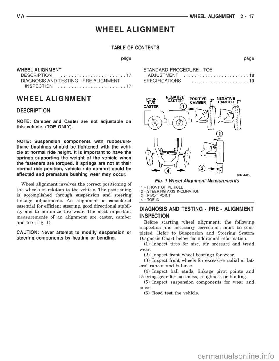
measurements of an alignment are caster, camber
and toe (Fig. 1).
CAUTION: Never attempt to modify suspension or
steering components by heating or bending.
DIAGNOSIS AND TESTING - PRE - ALIGNMENT
INSPECTION
Before starting wheel alignment, the following
inspection and necessary corrections must be com-
pleted. Refer to Suspension and Steering System
Diagnosis Chart below for additional information.
(1) Inspect tires for size, air pressure and tread
wear.
(2) Inspect front wheel bearings for wear.
(3) Inspect front wheels for excessive radial or lat-
eral runout and balance.
(4) Inspect ball studs, linkage pivot points and
steering gear for looseness, roughness or binding.
(5) Inspect suspension components for wear and
noise.
(6) Road test the vehicle.
Fig. 1 Wheel Alignment Measurements
1 - FRONT OF VEHICLE
2 - STEERING AXIS INCLINATION
3 - PIVOT POINT
4 - TOE-IN
VAWHEEL ALIGNMENT 2 - 17
Page 743 of 2305
SUSPENSION AND STEERING SYSTEM DIAGNOSIS
CONDITION POSSIBLE CAUSES CORRECTION
FRONT END NOISE 1. Loose or worn wheel bearing. 1. Replace wheel bearing.
2. Loose or worn steering or sus-
pension components.2. Tighten or replace components as nec-
essary.
3. Loose or worn steering or sus-
pension components.3. Tighten or replace components as nec-
essary.
EXCESSIVE PLAY IN
STEERING1. Loose or worn wheel bearing. 1. Replace wheel bearing.
2. Loose or worn steering or sus-
pension components.2. Tighten or replace components as nec-
essary.
3. Loose or worn steering gear. 3. Replace steering gear.
FRONT WHEELS SHIMMY 1. Loose or worn wheel bearing. 1. Replace wheel bearing.
2. Loose or worn steering or sus-
pension components.2. Tighten or replace components as nec-
essary.
3. Tires worn or out of balance. 3. Replace or balance tires.
4. Alignment. 4. Align vehicle to specifications.
VEHICLE INSTABILITY 1. Loose or worn wheel bearing. 1. Replace wheel bearing.
2. Loose or worn steering or sus-
pension components.2. Tighten or replace components as nec-
essary.
3. Tire pressure. 3. Adjust tire pressure.
4. Alignment. 4. Align vehicle to specifications.
EXCESSIVE STEERING
EFFORT1. Loose or worn steering gear. 1. Replace steering gear.
2. Column coupler binding. 2. Replace coupler.
3. Tire pressure. 3. Adjust tire pressure.
4. Alignment. 4. Align vehicle to specifications.
VEHICLE PULLS TO ONE
SIDE1. Tire pressure. 1. Adjust tire pressure.
2. Tire. 2. Criss-Cross Front Tires.
3. Alignment. 3. Align vehicle to specifications.
4. Loose or worn steering or sus-
pension components.4. Tighten or replace components as nec-
essary.
5. Radial tire lead. 5. Rotate or replace tire as necessary.
6. Brake pull. 6. Repair brake as necessary.
7. Weak or broken spring. 7. Replace spring.
STANDARD PROCEDURE - TOE ADJUSTMENT
CAMBER AND CASTER ARE NOT ADJUSTABLE
(TOE ONLY)..
The wheel toe position adjustment is the final
adjustment.
(1) Start the engine and turn wheels both ways
before straightening the wheels. Secure the steering
wheel with the front wheels in the straight-ahead
position.(2) Loosen the tie rod jam nuts.
NOTE: Each front wheel should be adjusted for
one-half of the total toe position specification. This
will ensure the steering wheel will be centered
when the wheels are positioned straight-ahead.
(3) Adjust the wheel toe position by turning the
inner tie rod as necessary.
2 - 18 WHEEL ALIGNMENTVA
Page 791 of 2305
POWER BRAKE BOOSTER
DESCRIPTION.........................19
OPERATION...........................19
REMOVAL.............................20
INSTALLATION.........................20
ROTORS
REMOVAL
REMOVAL - FRONT (SRW)..............20
REMOVAL - REAR (SRW)...............20
REMOVAL - FRONT (DRW)..............21
REMOVAL - REAR (DRW)...............21
INSTALLATION
INSTALLATION - FRONT (SRW)..........22
INSTALLATION - REAR (SRW)...........22
INSTALLATION - FRONT (DRW)..........22
INSTALLATION - REAR (DRW)...........22
SUPPORT PLATE
REMOVAL - REAR......................23
INSTALLATION - REAR...................23
PARKING BRAKE
SPECIFICATIONS
TORQUE CHART......................23
SPECIAL TOOLS
PARK BRAKE........................24
CABLE TENSIONER
REMOVAL.............................24INSTALLATION.........................24
CABLES
REMOVAL
REMOVAL - FRONT....................24
REMOVAL - REAR.....................25
INSTALLATION
INSTALLATION - FRONT................25
INSTALLATION - REAR.................26
ADJUSTMENTS
ADJUSTMENT - PARKING BRAKE CABLES . 26
LEVER
REMOVAL.............................26
INSTALLATION.........................27
SHOES
REMOVAL
REMOVAL - (SRW)....................27
REMOVAL - (DRW)....................27
CLEANING - REAR DRUM IN HAT BRAKE....28
INSTALLATION
INSTALLATION - (SRW).................28
INSTALLATION - (DRW).................28
ADJUSTMENTS
ADJUSTMENT........................28
BRAKES - BASE
DIAGNOSIS AND TESTING - BASE BRAKE SYS-
TEM
Base brake components consist of the brake pads,
calipers, brake drum in hat rotor in the rear, rotors,
brake lines, master cylinder, booster, and parking
brake components.
Brake diagnosis involves determining if the prob-
lem is related to a mechanical, hydraulic, or vacuum
operated component.
The first diagnosis step is the preliminary check.
PRELIMINARY BRAKE CHECK
(1) Check condition of tires and wheels. Damaged
wheels and worn, damaged, or underinflated tires
can cause pull, shudder, vibration, and a condition
similar to grab.
(2) If complaint was based on noise when braking,
check suspension components. Jounce front and rear
of vehicle and listen for noise that might be caused
by loose, worn or damaged suspension or steering
components.
(3) Inspect brake fluid level and condition. Note
that the brake reservoir fluid level will decrease in
proportion to normal lining wear.Also note that
brake fluid tends to darken over time. This is
normal and should not be mistaken for contam-
ination.(a) If fluid level is abnormally low, look for evi-
dence of leaks at calipers, wheel cylinders, brake
lines, and master cylinder.
(b) If fluid appears contaminated, drain out a
sample to examine. System will have to be flushed
if fluid is separated into layers, or contains a sub-
stance other than brake fluid. The system seals
and cups will also have to be replaced after flush-
ing. Use clean brake fluid to flush the system.
(4) Check parking brake operation. Verify free
movement and full release of cables and pedal. Also
note if vehicle was being operated with parking
brake partially applied.
(5) Check brake pedal operation. Verify that pedal
does not bind and has adequate free play. If pedal
lacks free play, check pedal and power booster for
being loose or for bind condition. Do not road test
until condition is corrected.
(6) Check booster vacuum check valve and hose.
(7) If components checked appear OK, road test
the vehicle.
ROAD TESTING
(1) If complaint involved low brake pedal, pump
pedal and note if it comes back up to normal height.
(2) Check brake pedal response with transmission
in Neutral and engine running. Pedal should remain
firm under constant foot pressure.
5 - 2 BRAKES - BASEVA
Page 953 of 2305
seat riser, a fog lamp switch installed in the cluster
bezel on the instrument panel outboard of the steer-
ing column, and a fog lamp bulb installed in each of
the two front lamp units. The front fog lamps have a
path to ground at all times through their connection
to the vehicle wire harness. The headlamp switch cir-
cuitry of the left (lighting) control stalk of the multi-
function switch controls front fog lamp operation by
providing battery current to the front fog lamp relay
only when the low beam headlamps are selected. The
fog lamp switch controls front fog lamp operation by
energizing or de-energizing the front fog lamp relay
control coil.
HAZARD WARNING LAMPS
With the hazard switch in the On position, the
hazard switch button illuminates and the right and
left turn signal indicators as well as the right and
left turn signal lamps begin to flash on and off. When
the hazard warning system is activated, the hazard
switch circuitry within the multi-function switch and
the wipers, turn signals and engine start control
module electronic circuitry within the fuse block will
repeatedly energize and de-energize the turn signal
relay located in the fuse block. The turn signal relay
switches battery current from a fused B(+) fuse in
the fuse block to the turn signal indicators and the
turn signal lamps. The flashing of the hazard switch
button illumination lamp is also controlled by the
output from the turn signal relay.
HEADLAMPS
The headlamp system includes the exterior lighting
switches integral to the left (lighting) control stalk of
the multi-function switch as well as the low and high
beam bulbs installed in the right and left front lamp
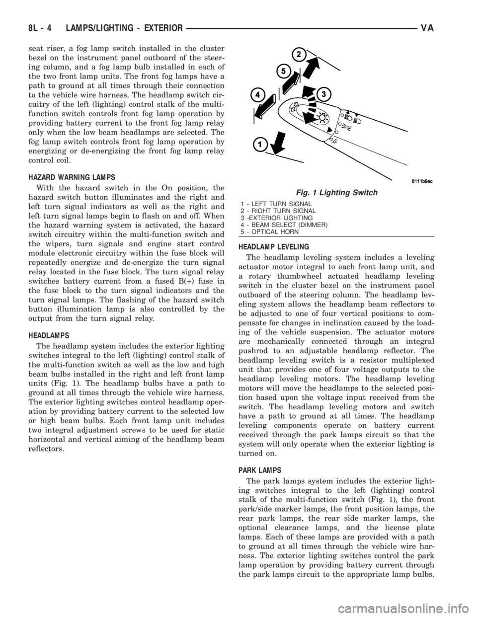
units (Fig. 1). The headlamp bulbs have a path to
ground at all times through the vehicle wire harness.
The exterior lighting switches control headlamp oper-
ation by providing battery current to the selected low
or high beam bulbs. Each front lamp unit includes
two integral adjustment screws to be used for static
horizontal and vertical aiming of the headlamp beam
reflectors.HEADLAMP LEVELING
The headlamp leveling system includes a leveling
actuator motor integral to each front lamp unit, and
a rotary thumbwheel actuated headlamp leveling
switch in the cluster bezel on the instrument panel
outboard of the steering column. The headlamp lev-
eling system allows the headlamp beam reflectors to
be adjusted to one of four vertical positions to com-
pensate for changes in inclination caused by the load-
ing of the vehicle suspension. The actuator motors
are mechanically connected through an integral
pushrod to an adjustable headlamp reflector. The
headlamp leveling switch is a resistor multiplexed
unit that provides one of four voltage outputs to the
headlamp leveling motors. The headlamp leveling
motors will move the headlamps to the selected posi-
tion based upon the voltage input received from the
switch. The headlamp leveling motors and switch
have a path to ground at all times. The headlamp
leveling components operate on battery current
received through the park lamps circuit so that the
system will only operate when the exterior lighting is
turned on.
PARK LAMPS
The park lamps system includes the exterior light-
ing switches integral to the left (lighting) control
stalk of the multi-function switch (Fig. 1), the front
park/side marker lamps, the front position lamps, the
rear park lamps, the rear side marker lamps, the
optional clearance lamps, and the license plate
lamps. Each of these lamps are provided with a path
to ground at all times through the vehicle wire har-
ness. The exterior lighting switches control the park
lamp operation by providing battery current through
the park lamps circuit to the appropriate lamp bulbs.
Fig. 1 Lighting Switch
1 - LEFT TURN SIGNAL
2 - RIGHT TURN SIGNAL
3 -EXTERIOR LIGHTING
4 - BEAM SELECT (DIMMER)
5 - OPTICAL HORN
8L - 4 LAMPS/LIGHTING - EXTERIORVA
Page 956 of 2305
INSTALLATION
WARNING: To avoid personal injury or death, on
vehicles equipped with airbags, disable the supple-
mental restraint system before attempting any
steering wheel, steering column, airbag, seat belt
tensioner, or instrument panel component diagno-
sis or service. Disconnect and isolate the battery
negative (ground) cable, then wait two minutes for
the system capacitor to discharge before perform-
ing further diagnosis or service. This is the only
sure way to disable the supplemental restraint sys-
tem. Failure to take the proper precautions could
result in accidental airbag deployment.
(1) Pull the plunger of the brake lamp switch out-
ward from the switch body to its travel limit (Fig. 5).
(2) Reconnect the vehicle wire harness to the
brake lamp switch connector receptacle.
(3) Depress and hold the brake pedal in the
depressed position until the brake lamp switch
installation is completed (Fig. 4).
(4) Insert the brake lamp switch plunger through
the mounting hole from behind until the switch lock-
ing collar is fully seated against the pedal bracket.
(5) Rotate the brake lamp switch clockwise until
the locking tab on the switch body fully engages the
pedal bracket. Full locking tab engagement will be
accompanied by an audible click.
NOTE: Do not pull the brake pedal upwards as this
will adjust the switch plunger to an incorrect posi-
tion. The switch is properly adjusted when the
switch plunger is just contacting (no gap) the brake
pedal arm with the pedal in the relaxed (released)
position.
(6) Release the brake pedal from its depressed
position to automatically adjust the brake lamp
switch plunger.
(7) Reconnect the battery negative cable.
ADJUSTMENTS
ADJUSTMENT
WARNING: To avoid personal injury or death, on
vehicles equipped with airbags, disable the supple-
mental restraint system before attempting any
steering wheel, steering column, airbag, seat belt
tensioner, or instrument panel component diagno-
sis or service. Disconnect and isolate the battery
negative (ground) cable, then wait two minutes for
the system capacitor to discharge before perform-
ing further diagnosis or service. This is the only
sure way to disable the supplemental restraint sys-tem. Failure to take the proper precautions could
result in accidental airbag deployment.
(1) Disconnect and isolate the battery negative
cable.
(2) Depress and hold the brake pedal in the
depressed position until the brake lamp switch
adjustment is completed.
(3) Pull the plunger of the brake lamp switch out-
ward from the switch body to its travel limit.
NOTE: Do not pull the brake pedal upwards as this
will adjust the switch plunger to an incorrect posi-
tion. The switch is properly adjusted when the
switch plunger is just contacting (no gap) the brake
pedal arm with the pedal in the relaxed (released)
position.
(4) Release the brake pedal from its depressed
position to automatically adjust the brake lamp
switch plunger.
BRAKE / PARK LAMP BULB
REMOVAL
(1) Disconnect and isolate the battery negative
cable.
(2) If the vehicle is so equipped, remove the trim
from the inside of the right or left rear corner pillar.
(3) From inside the vehicle, use hand pressure to
push the two latch tabs toward the center of the tail
lamp unit socket plate and pull the socket plate
straight out from the inner rear pillar (Fig. 6).
VALAMPS/LIGHTING - EXTERIOR 8L - 7
Page 1732 of 2305
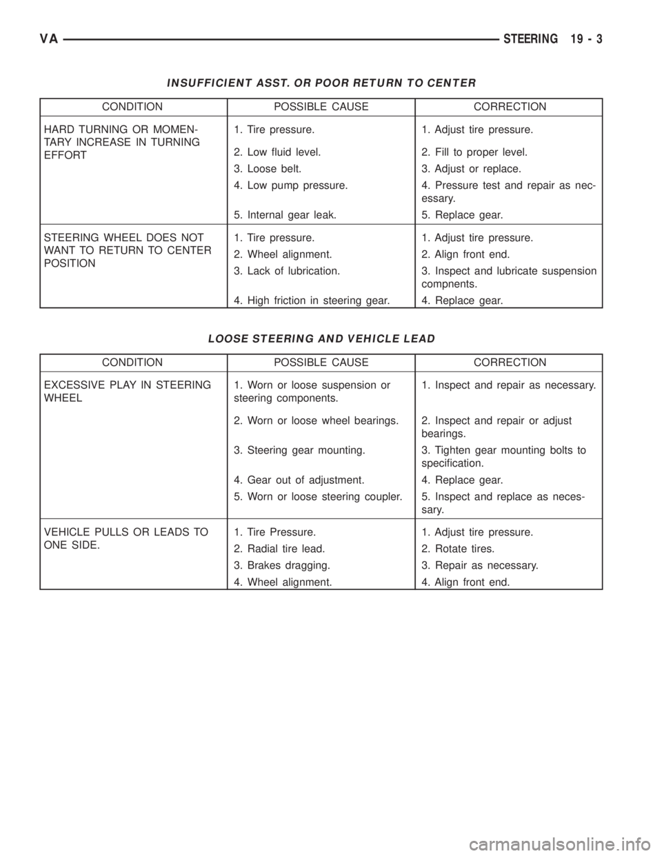
INSUFFICIENT ASST. OR POOR RETURN TO CENTER
CONDITION POSSIBLE CAUSE CORRECTION
HARD TURNING OR MOMEN-
TARY INCREASE IN TURNING
EFFORT1. Tire pressure. 1. Adjust tire pressure.
2. Low fluid level. 2. Fill to proper level.
3. Loose belt. 3. Adjust or replace.
4. Low pump pressure. 4. Pressure test and repair as nec-
essary.
5. Internal gear leak. 5. Replace gear.
STEERING WHEEL DOES NOT
WANT TO RETURN TO CENTER
POSITION1. Tire pressure. 1. Adjust tire pressure.
2. Wheel alignment. 2. Align front end.
3. Lack of lubrication. 3. Inspect and lubricate suspension
compnents.
4. High friction in steering gear. 4. Replace gear.
LOOSE STEERING AND VEHICLE LEAD
CONDITION POSSIBLE CAUSE CORRECTION
EXCESSIVE PLAY IN STEERING
WHEEL1. Worn or loose suspension or
steering components.1. Inspect and repair as necessary.
2. Worn or loose wheel bearings. 2. Inspect and repair or adjust
bearings.
3. Steering gear mounting. 3. Tighten gear mounting bolts to
specification.
4. Gear out of adjustment. 4. Replace gear.
5. Worn or loose steering coupler. 5. Inspect and replace as neces-
sary.
VEHICLE PULLS OR LEADS TO
ONE SIDE.1. Tire Pressure. 1. Adjust tire pressure.
2. Radial tire lead. 2. Rotate tires.
3. Brakes dragging. 3. Repair as necessary.
4. Wheel alignment. 4. Align front end.
VASTEERING 19 - 3
Page 1737 of 2305
torque to 45 N´m (33 ft. lbs.) and a final additional
90É turn for final torque.
(3) Install the universal joint to the steering gear
(Fig. 2). Tighten to 24 N´m (18 ft. lbs.).
(4) Install both the power steering hoses to the
steering gear (Fig. 2). Tighten the high pressure hose
to 37 N´m (27 ft. lbs.).
(5) Install the spring clamp plates (Refer to 2 -
SUSPENSION/FRONT/SPRING CLAMP PLATES -
INSTALLATION).
(6) Install the left outer tie rod end to the steering
gear.(7) Install both the outer tie rod ends to the steer-
ing knuckle (Fig. 2). Tighten to 130 N´m (96 ft. lbs.).
(8) Install the upper stabilizer bar link to the sta-
bilizer bar.
(9) Install the front wheels.
(10) Fill and bleed the power steering system
(Refer to 19 - STEERING/PUMP/FLUID - STAN-
DARD PROCEDURE).
(11) Reset toe adjustment.
(12) Check steering system for leaks.
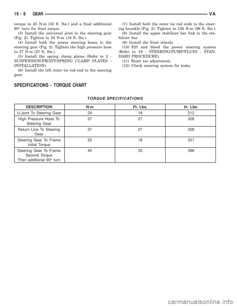
SPECIFICATIONS - TORQUE CHART
TORQUE SPECIFICATIONS
DESCRIPTION N´m Ft. Lbs. In. Lbs.
U-Joint To Steering Gear 24 18 212
High Pressure Hose To
Steering Gear37 27 328
Return Line To Steering
Gear37 27 328
Steering Gear To Frame
Initial Torque25 18 221
Steering Gear To Frame
Second Torque
Then additional 90É turn45 33 398
19 - 8 GEARVA
Page 1739 of 2305
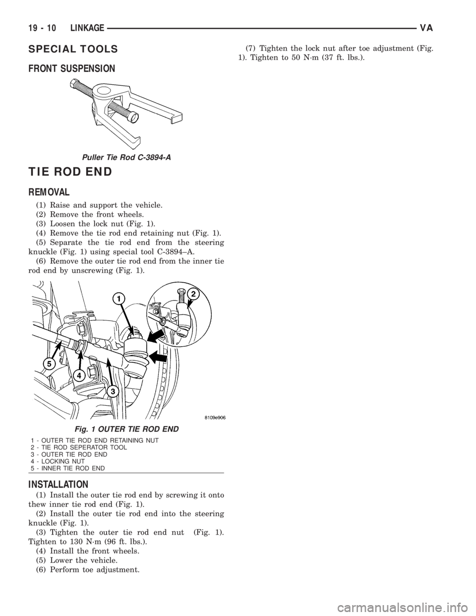
SPECIAL TOOLS
FRONT SUSPENSION
TIE ROD END
REMOVAL
(1) Raise and support the vehicle.
(2) Remove the front wheels.
(3) Loosen the lock nut (Fig. 1).
(4) Remove the tie rod end retaining nut (Fig. 1).
(5) Separate the tie rod end from the steering
knuckle (Fig. 1) using special tool C-3894±A.
(6) Remove the outer tie rod end from the inner tie
rod end by unscrewing (Fig. 1).
INSTALLATION
(1) Install the outer tie rod end by screwing it onto
thew inner tie rod end (Fig. 1).
(2) Install the outer tie rod end into the steering
knuckle (Fig. 1).
(3) Tighten the outer tie rod end nut (Fig. 1).
Tighten to 130 N´m (96 ft. lbs.).
(4) Install the front wheels.
(5) Lower the vehicle.
(6) Perform toe adjustment.(7) Tighten the lock nut after toe adjustment (Fig.
1). Tighten to 50 N´m (37 ft. lbs.).
Puller Tie Rod C-3894-A
Fig. 1 OUTER TIE ROD END
1 - OUTER TIE ROD END RETAINING NUT
2 - TIE ROD SEPERATOR TOOL
3 - OUTER TIE ROD END
4 - LOCKING NUT
5 - INNER TIE ROD END
19 - 10 LINKAGEVA