2006 MERCEDES-BENZ SPRINTER lock
[x] Cancel search: lockPage 1903 of 2305
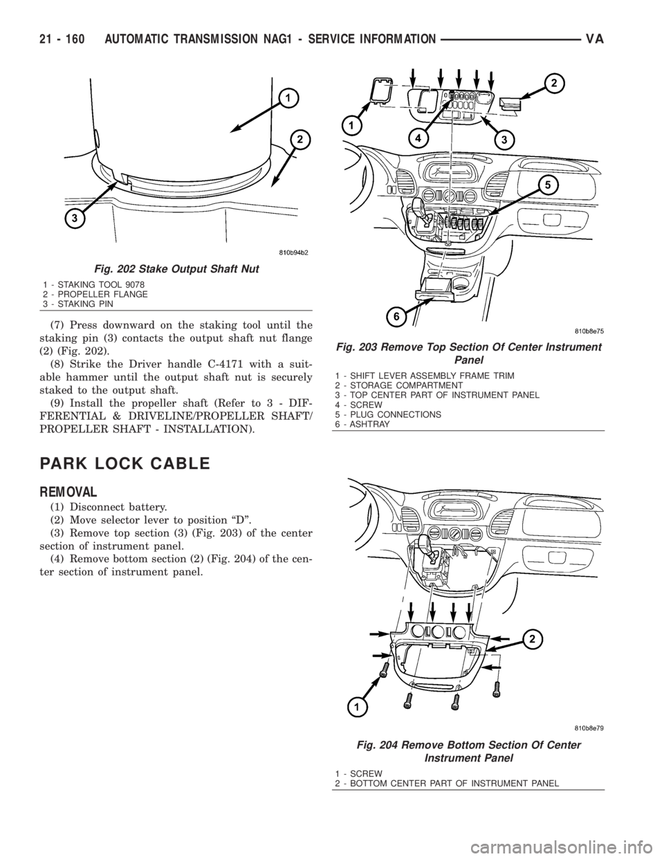
(7) Press downward on the staking tool until the
staking pin (3) contacts the output shaft nut flange
(2) (Fig. 202).
(8) Strike the Driver handle C-4171 with a suit-
able hammer until the output shaft nut is securely
staked to the output shaft.
(9) Install the propeller shaft (Refer to 3 - DIF-
FERENTIAL & DRIVELINE/PROPELLER SHAFT/
PROPELLER SHAFT - INSTALLATION).
PARK LOCK CABLE
REMOVAL
(1) Disconnect battery.
(2) Move selector lever to position ªDº.
(3) Remove top section (3) (Fig. 203) of the center
section of instrument panel.
(4) Remove bottom section (2) (Fig. 204) of the cen-
ter section of instrument panel.
Fig. 202 Stake Output Shaft Nut
1 - STAKING TOOL 9078
2 - PROPELLER FLANGE
3 - STAKING PIN
Fig. 203 Remove Top Section Of Center Instrument
Panel
1 - SHIFT LEVER ASSEMBLY FRAME TRIM
2 - STORAGE COMPARTMENT
3 - TOP CENTER PART OF INSTRUMENT PANEL
4 - SCREW
5 - PLUG CONNECTIONS
6 - ASHTRAY
Fig. 204 Remove Bottom Section Of Center
Instrument Panel
1 - SCREW
2 - BOTTOM CENTER PART OF INSTRUMENT PANEL
21 - 160 AUTOMATIC TRANSMISSION NAG1 - SERVICE INFORMATIONVA
Page 1904 of 2305
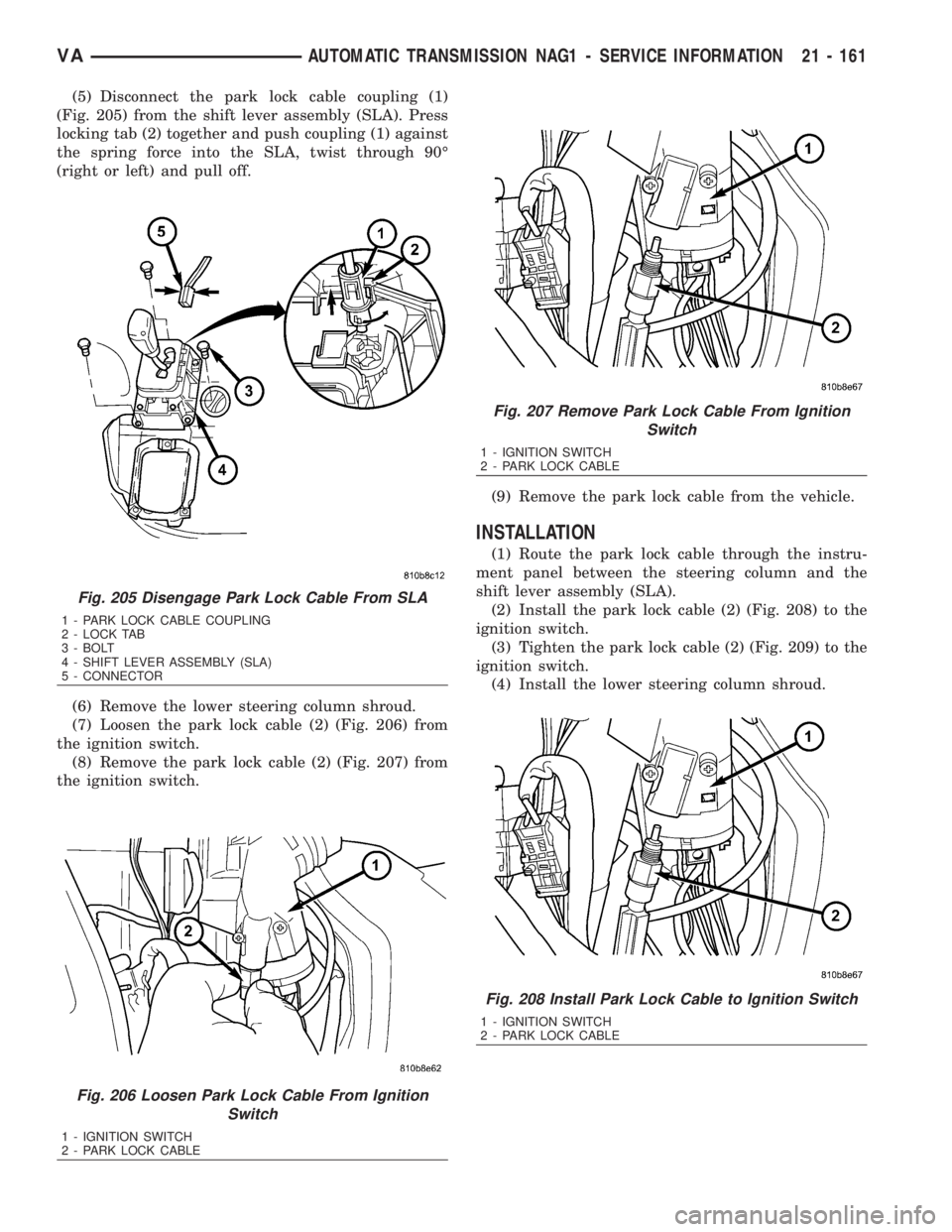
(5) Disconnect the park lock cable coupling (1)
(Fig. 205) from the shift lever assembly (SLA). Press
locking tab (2) together and push coupling (1) against
the spring force into the SLA, twist through 90É
(right or left) and pull off.
(6) Remove the lower steering column shroud.
(7) Loosen the park lock cable (2) (Fig. 206) from
the ignition switch.
(8) Remove the park lock cable (2) (Fig. 207) from
the ignition switch.(9) Remove the park lock cable from the vehicle.
INSTALLATION
(1) Route the park lock cable through the instru-
ment panel between the steering column and the
shift lever assembly (SLA).
(2) Install the park lock cable (2) (Fig. 208) to the
ignition switch.
(3) Tighten the park lock cable (2) (Fig. 209) to the
ignition switch.
(4) Install the lower steering column shroud.
Fig. 205 Disengage Park Lock Cable From SLA
1 - PARK LOCK CABLE COUPLING
2 - LOCK TAB
3 - BOLT
4 - SHIFT LEVER ASSEMBLY (SLA)
5 - CONNECTOR
Fig. 206 Loosen Park Lock Cable From Ignition
Switch
1 - IGNITION SWITCH
2 - PARK LOCK CABLE
Fig. 207 Remove Park Lock Cable From Ignition
Switch
1 - IGNITION SWITCH
2 - PARK LOCK CABLE
Fig. 208 Install Park Lock Cable to Ignition Switch
1 - IGNITION SWITCH
2 - PARK LOCK CABLE
VAAUTOMATIC TRANSMISSION NAG1 - SERVICE INFORMATION 21 - 161
Page 1905 of 2305
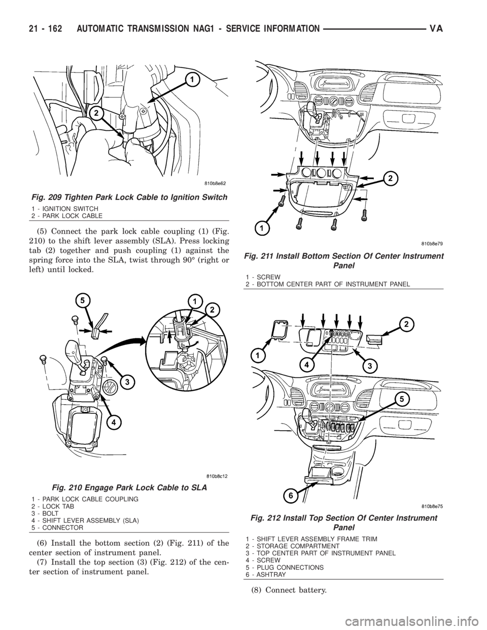
(5) Connect the park lock cable coupling (1) (Fig.
210) to the shift lever assembly (SLA). Press locking
tab (2) together and push coupling (1) against the
spring force into the SLA, twist through 90É (right or
left) until locked.
(6) Install the bottom section (2) (Fig. 211) of the
center section of instrument panel.
(7) Install the top section (3) (Fig. 212) of the cen-
ter section of instrument panel.
(8) Connect battery.
Fig. 209 Tighten Park Lock Cable to Ignition Switch
1 - IGNITION SWITCH
2 - PARK LOCK CABLE
Fig. 210 Engage Park Lock Cable to SLA
1 - PARK LOCK CABLE COUPLING
2 - LOCK TAB
3 - BOLT
4 - SHIFT LEVER ASSEMBLY (SLA)
5 - CONNECTOR
Fig. 211 Install Bottom Section Of Center Instrument
Panel
1 - SCREW
2 - BOTTOM CENTER PART OF INSTRUMENT PANEL
Fig. 212 Install Top Section Of Center Instrument
Panel
1 - SHIFT LEVER ASSEMBLY FRAME TRIM
2 - STORAGE COMPARTMENT
3 - TOP CENTER PART OF INSTRUMENT PANEL
4 - SCREW
5 - PLUG CONNECTIONS
6 - ASHTRAY
21 - 162 AUTOMATIC TRANSMISSION NAG1 - SERVICE INFORMATIONVA
Page 1906 of 2305
(9) Verify repair.
PISTONS
DESCRIPTION
There are several sizes and types of pistons used in
an automatic transmission. Some pistons are used to
apply clutches. They all have in common the fact
that they are round or circular in shape, located
within a smooth walled cylinder, which is closed at
one end and converts fluid pressure into mechanical
movement. The fluid pressure exerted on the piston
is contained within the system through the use of
piston rings or seals.
OPERATION
The principal which makes this operation possible
is known as Pascal's Law. Pascal's Law can be stated
as: ªPressure on a confined fluid is transmitted
equally in all directions and acts with equal force on
equal areas.º
PRESSURE
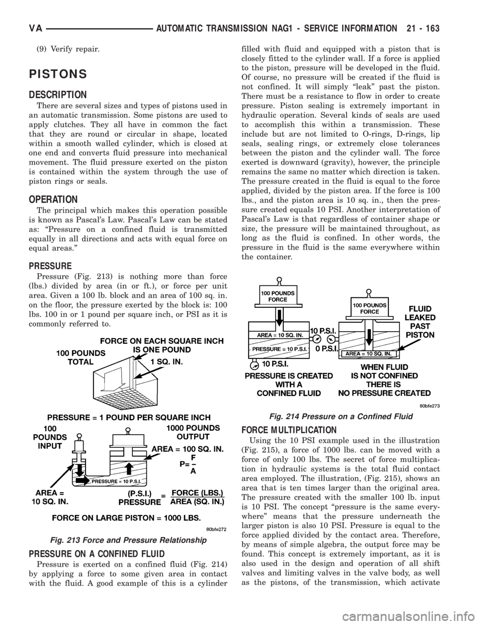
Pressure (Fig. 213) is nothing more than force
(lbs.) divided by area (in or ft.), or force per unit
area. Given a 100 lb. block and an area of 100 sq. in.
on the floor, the pressure exerted by the block is: 100
lbs. 100 in or 1 pound per square inch, or PSI as it is
commonly referred to.
PRESSURE ON A CONFINED FLUID
Pressure is exerted on a confined fluid (Fig. 214)
by applying a force to some given area in contact
with the fluid. A good example of this is a cylinderfilled with fluid and equipped with a piston that is
closely fitted to the cylinder wall. If a force is applied
to the piston, pressure will be developed in the fluid.
Of course, no pressure will be created if the fluid is
not confined. It will simply ªleakº past the piston.
There must be a resistance to flow in order to create
pressure. Piston sealing is extremely important in
hydraulic operation. Several kinds of seals are used
to accomplish this within a transmission. These
include but are not limited to O-rings, D-rings, lip
seals, sealing rings, or extremely close tolerances
between the piston and the cylinder wall. The force
exerted is downward (gravity), however, the principle
remains the same no matter which direction is taken.
The pressure created in the fluid is equal to the force
applied, divided by the piston area. If the force is 100
lbs., and the piston area is 10 sq. in., then the pres-
sure created equals 10 PSI. Another interpretation of
Pascal's Law is that regardless of container shape or
size, the pressure will be maintained throughout, as
long as the fluid is confined. In other words, the
pressure in the fluid is the same everywhere within
the container.
FORCE MULTIPLICATION
Using the 10 PSI example used in the illustration
(Fig. 215), a force of 1000 lbs. can be moved with a
force of only 100 lbs. The secret of force multiplica-
tion in hydraulic systems is the total fluid contact
area employed. The illustration, (Fig. 215), shows an
area that is ten times larger than the original area.
The pressure created with the smaller 100 lb. input
is 10 PSI. The concept ªpressure is the same every-
whereº means that the pressure underneath the
larger piston is also 10 PSI. Pressure is equal to the
force applied divided by the contact area. Therefore,
by means of simple algebra, the output force may be
found. This concept is extremely important, as it is
also used in the design and operation of all shift
valves and limiting valves in the valve body, as well
as the pistons, of the transmission, which activate
Fig. 213 Force and Pressure Relationship
Fig. 214 Pressure on a Confined Fluid
VAAUTOMATIC TRANSMISSION NAG1 - SERVICE INFORMATION 21 - 163
Page 1908 of 2305
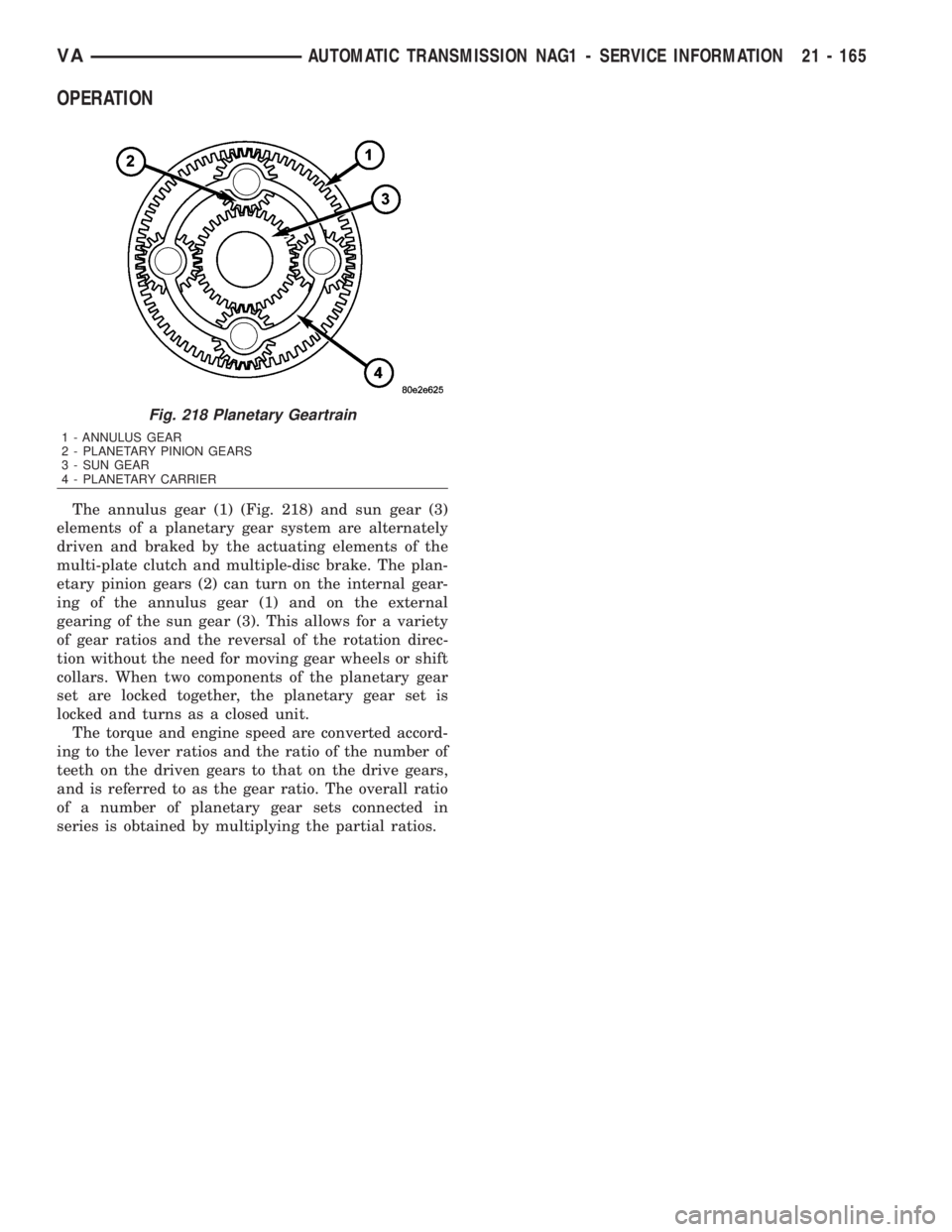
OPERATION
The annulus gear (1) (Fig. 218) and sun gear (3)
elements of a planetary gear system are alternately
driven and braked by the actuating elements of the
multi-plate clutch and multiple-disc brake. The plan-
etary pinion gears (2) can turn on the internal gear-
ing of the annulus gear (1) and on the external
gearing of the sun gear (3). This allows for a variety
of gear ratios and the reversal of the rotation direc-
tion without the need for moving gear wheels or shift
collars. When two components of the planetary gear
set are locked together, the planetary gear set is
locked and turns as a closed unit.
The torque and engine speed are converted accord-
ing to the lever ratios and the ratio of the number of
teeth on the driven gears to that on the drive gears,
and is referred to as the gear ratio. The overall ratio
of a number of planetary gear sets connected in
series is obtained by multiplying the partial ratios.
Fig. 218 Planetary Geartrain
1 - ANNULUS GEAR
2 - PLANETARY PINION GEARS
3 - SUN GEAR
4 - PLANETARY CARRIER
VAAUTOMATIC TRANSMISSION NAG1 - SERVICE INFORMATION 21 - 165
Page 1911 of 2305
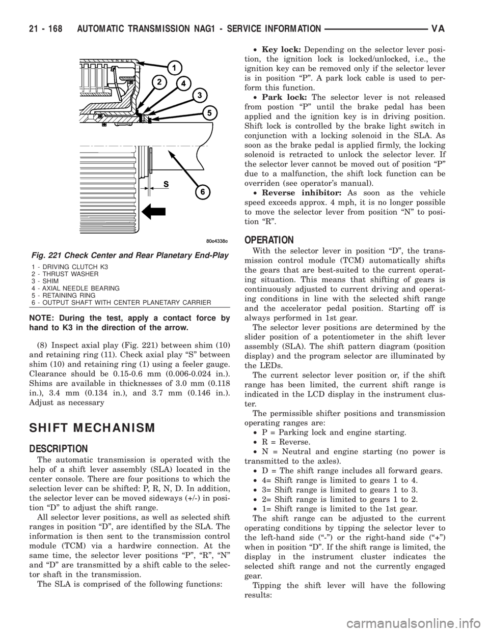
NOTE: During the test, apply a contact force by
hand to K3 in the direction of the arrow.
(8) Inspect axial play (Fig. 221) between shim (10)
and retaining ring (11). Check axial play ªSº between
shim (10) and retaining ring (1) using a feeler gauge.
Clearance should be 0.15-0.6 mm (0.006-0.024 in.).
Shims are available in thicknesses of 3.0 mm (0.118
in.), 3.4 mm (0.134 in.), and 3.7 mm (0.146 in.).
Adjust as necessary
SHIFT MECHANISM
DESCRIPTION
The automatic transmission is operated with the
help of a shift lever assembly (SLA) located in the
center console. There are four positions to which the
selection lever can be shifted: P, R, N, D. In addition,
the selector lever can be moved sideways (+/-) in posi-
tion ªDº to adjust the shift range.
All selector lever positions, as well as selected shift
ranges in position ªDº, are identified by the SLA. The
information is then sent to the transmission control
module (TCM) via a hardwire connection. At the
same time, the selector lever positions ªPº, ªRº, ªNº
and ªDº are transmitted by a shift cable to the selec-
tor shaft in the transmission.
The SLA is comprised of the following functions:²Key lock:Depending on the selector lever posi-
tion, the ignition lock is locked/unlocked, i.e., the
ignition key can be removed only if the selector lever
is in position ªPº. A park lock cable is used to per-
form this function.
²Park lock:The selector lever is not released
from postion ªPº until the brake pedal has been
applied and the ignition key is in driving position.
Shift lock is controlled by the brake light switch in
conjunction with a locking solenoid in the SLA. As
soon as the brake pedal is applied firmly, the locking
solenoid is retracted to unlock the selector lever. If
the selector lever cannot be moved out of position ªPº
due to a malfunction, the shift lock function can be
overriden (see operator's manual).
²Reverse inhibitor:As soon as the vehicle
speed exceeds approx. 4 mph, it is no longer possible
to move the selector lever from position ªNº to posi-
tion ªRº.
OPERATION
With the selector lever in position ªDº, the trans-
mission control module (TCM) automatically shifts
the gears that are best-suited to the current operat-
ing situation. This means that shifting of gears is
continuously adjusted to current driving and operat-
ing conditions in line with the selected shift range
and the accelerator pedal position. Starting off is
always performed in 1st gear.
The selector lever positions are determined by the
slider position of a potentiometer in the shift lever
assembly (SLA). The shift pattern diagram (position
display) and the program selector are illuminated by
the LEDs.
The current selector lever position or, if the shift
range has been limited, the current shift range is
indicated in the LCD display in the instrument clus-
ter.
The permissible shifter positions and transmission
operating ranges are:
²P = Parking lock and engine starting.
²R = Reverse.
²N = Neutral and engine starting (no power is
transmitted to the axles).
²D = The shift range includes all forward gears.
²4= Shift range is limited to gears 1 to 4.
²3= Shift range is limited to gears 1 to 3.
²2= Shift range is limited to gears 1 to 2.
²1= Shift range is limited to the 1st gear.
The shift range can be adjusted to the current
operating conditions by tipping the selector lever to
the left-hand side (ª-º) or the right-hand side (ª+º)
when in position ªDº. If the shift range is limited, the
display in the instrument cluster indicates the
selected shift range and not the currently engaged
gear.
Tipping the shift lever will have the following
results:Fig. 221 Check Center and Rear Planetary End-Play
1 - DRIVING CLUTCH K3
2 - THRUST WASHER
3 - SHIM
4 - AXIAL NEEDLE BEARING
5 - RETAINING RING
6 - OUTPUT SHAFT WITH CENTER PLANETARY CARRIER
21 - 168 AUTOMATIC TRANSMISSION NAG1 - SERVICE INFORMATIONVA
Page 1913 of 2305
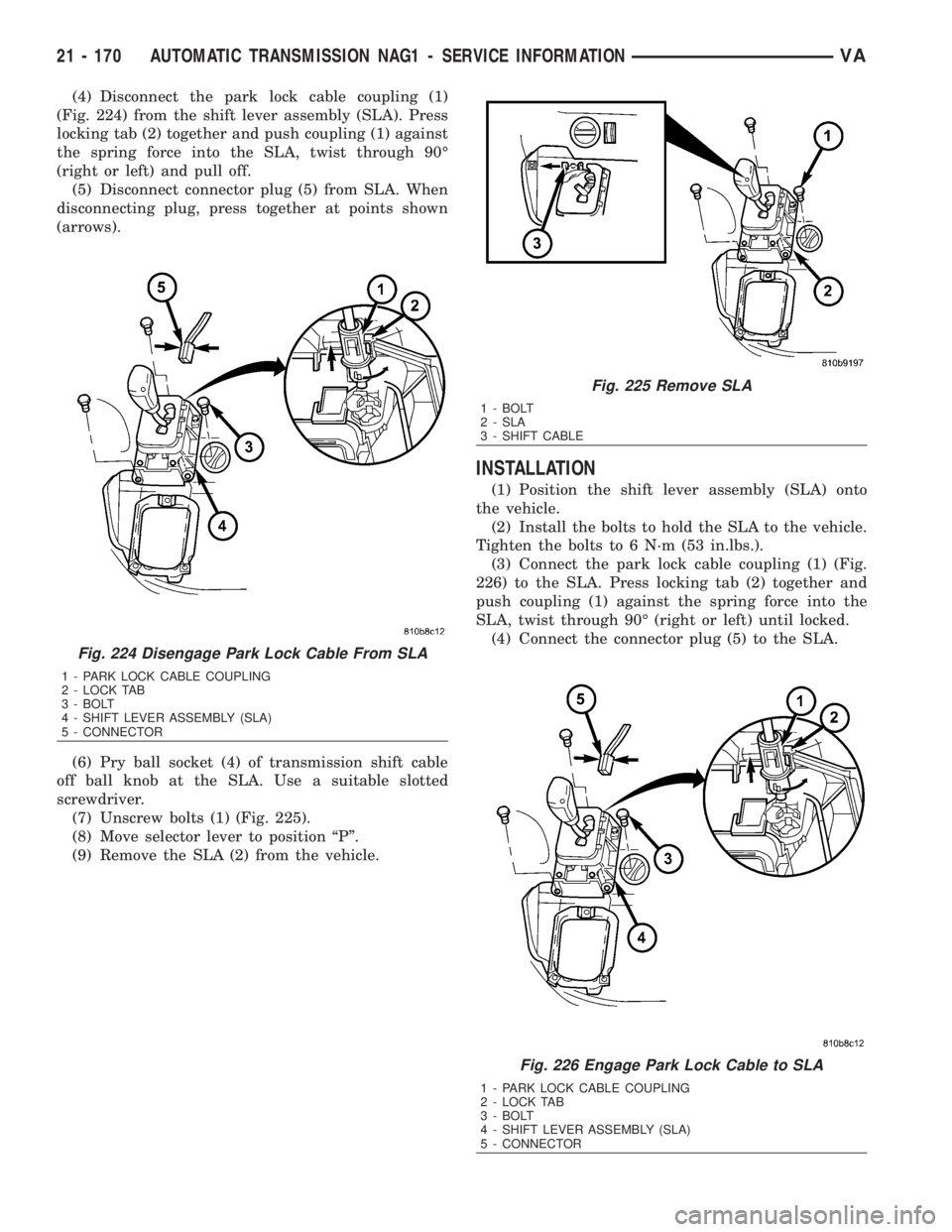
(4) Disconnect the park lock cable coupling (1)
(Fig. 224) from the shift lever assembly (SLA). Press
locking tab (2) together and push coupling (1) against
the spring force into the SLA, twist through 90É
(right or left) and pull off.
(5) Disconnect connector plug (5) from SLA. When
disconnecting plug, press together at points shown
(arrows).
(6) Pry ball socket (4) of transmission shift cable
off ball knob at the SLA. Use a suitable slotted
screwdriver.
(7) Unscrew bolts (1) (Fig. 225).
(8) Move selector lever to position ªPº.
(9) Remove the SLA (2) from the vehicle.
INSTALLATION
(1) Position the shift lever assembly (SLA) onto
the vehicle.
(2) Install the bolts to hold the SLA to the vehicle.
Tighten the bolts to 6 N´m (53 in.lbs.).
(3) Connect the park lock cable coupling (1) (Fig.
226) to the SLA. Press locking tab (2) together and
push coupling (1) against the spring force into the
SLA, twist through 90É (right or left) until locked.
(4) Connect the connector plug (5) to the SLA.
Fig. 224 Disengage Park Lock Cable From SLA
1 - PARK LOCK CABLE COUPLING
2 - LOCK TAB
3 - BOLT
4 - SHIFT LEVER ASSEMBLY (SLA)
5 - CONNECTOR
Fig. 225 Remove SLA
1 - BOLT
2 - SLA
3 - SHIFT CABLE
Fig. 226 Engage Park Lock Cable to SLA
1 - PARK LOCK CABLE COUPLING
2 - LOCK TAB
3 - BOLT
4 - SHIFT LEVER ASSEMBLY (SLA)
5 - CONNECTOR
21 - 170 AUTOMATIC TRANSMISSION NAG1 - SERVICE INFORMATIONVA
Page 1916 of 2305
MODULATING PRESSURE CONTROL SOLENOID
VALVE
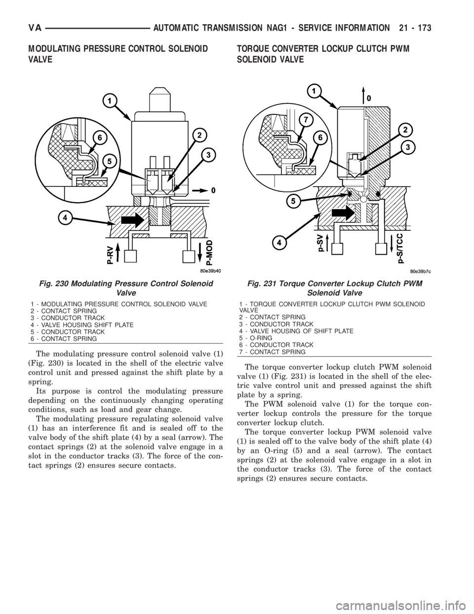
The modulating pressure control solenoid valve (1)
(Fig. 230) is located in the shell of the electric valve
control unit and pressed against the shift plate by a
spring.
Its purpose is control the modulating pressure
depending on the continuously changing operating
conditions, such as load and gear change.
The modulating pressure regulating solenoid valve
(1) has an interference fit and is sealed off to the
valve body of the shift plate (4) by a seal (arrow). The
contact springs (2) at the solenoid valve engage in a
slot in the conductor tracks (3). The force of the con-
tact springs (2) ensures secure contacts.
TORQUE CONVERTER LOCKUP CLUTCH PWM
SOLENOID VALVE
The torque converter lockup clutch PWM solenoid
valve (1) (Fig. 231) is located in the shell of the elec-
tric valve control unit and pressed against the shift
plate by a spring.
The PWM solenoid valve (1) for the torque con-
verter lockup controls the pressure for the torque
converter lockup clutch.
The torque converter lockup PWM solenoid valve
(1) is sealed off to the valve body of the shift plate (4)
by an O-ring (5) and a seal (arrow). The contact
springs (2) at the solenoid valve engage in a slot in
the conductor tracks (3). The force of the contact
springs (2) ensures secure contacts.
Fig. 230 Modulating Pressure Control Solenoid
Valve
1 - MODULATING PRESSURE CONTROL SOLENOID VALVE
2 - CONTACT SPRING
3 - CONDUCTOR TRACK
4 - VALVE HOUSING SHIFT PLATE
5 - CONDUCTOR TRACK
6 - CONTACT SPRING
Fig. 231 Torque Converter Lockup Clutch PWM
Solenoid Valve
1 - TORQUE CONVERTER LOCKUP CLUTCH PWM SOLENOID
VA LV E
2 - CONTACT SPRING
3 - CONDUCTOR TRACK
4 - VALVE HOUSING OF SHIFT PLATE
5 - O-RING
6 - CONDUCTOR TRACK
7 - CONTACT SPRING
VAAUTOMATIC TRANSMISSION NAG1 - SERVICE INFORMATION 21 - 173