2006 MERCEDES-BENZ SPRINTER lock
[x] Cancel search: lockPage 1783 of 2305
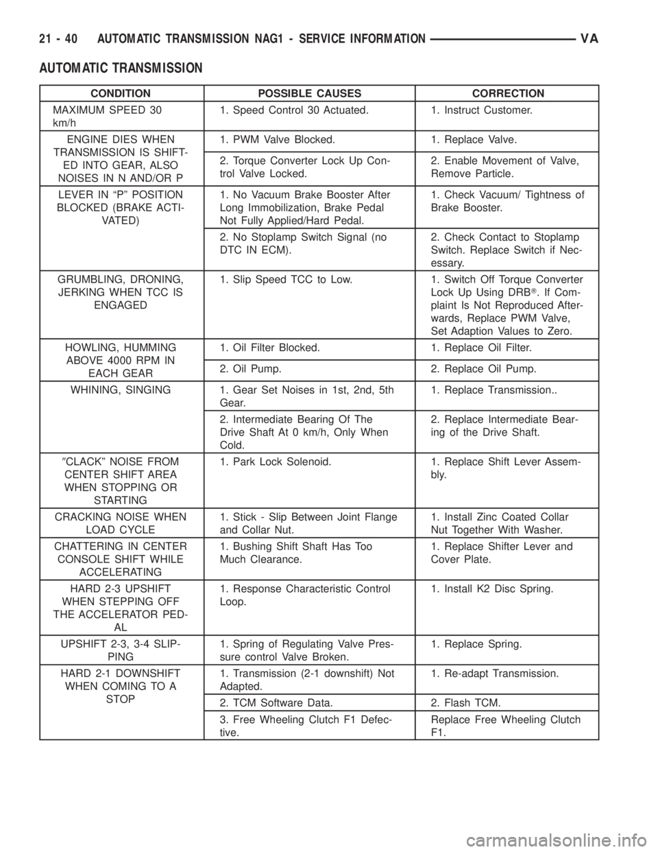
AUTOMATIC TRANSMISSION
CONDITION POSSIBLE CAUSES CORRECTION
MAXIMUM SPEED 30
km/h1. Speed Control 30 Actuated. 1. Instruct Customer.
ENGINE DIES WHEN
TRANSMISSION IS SHIFT-
ED INTO GEAR, ALSO
NOISES IN N AND/OR P1. PWM Valve Blocked. 1. Replace Valve.
2. Torque Converter Lock Up Con-
trol Valve Locked.2. Enable Movement of Valve,
Remove Particle.
LEVER IN ªPº POSITION
BLOCKED (BRAKE ACTI-
VATED)1. No Vacuum Brake Booster After
Long Immobilization, Brake Pedal
Not Fully Applied/Hard Pedal.1. Check Vacuum/ Tightness of
Brake Booster.
2. No Stoplamp Switch Signal (no
DTC IN ECM).2. Check Contact to Stoplamp
Switch. Replace Switch if Nec-
essary.
GRUMBLING, DRONING,
JERKING WHEN TCC IS
ENGAGED1. Slip Speed TCC to Low. 1. Switch Off Torque Converter
Lock Up Using DRBT. If Com-
plaint Is Not Reproduced After-
wards, Replace PWM Valve,
Set Adaption Values to Zero.
HOWLING, HUMMING
ABOVE 4000 RPM IN
EACH GEAR1. Oil Filter Blocked. 1. Replace Oil Filter.
2. Oil Pump. 2. Replace Oil Pump.
WHINING, SINGING 1. Gear Set Noises in 1st, 2nd, 5th
Gear.1. Replace Transmission..
2. Intermediate Bearing Of The
Drive Shaft At 0 km/h, Only When
Cold.2. Replace Intermediate Bear-
ing of the Drive Shaft.
9CLACKº NOISE FROM
CENTER SHIFT AREA
WHEN STOPPING OR
STARTING1. Park Lock Solenoid. 1. Replace Shift Lever Assem-
bly.
CRACKING NOISE WHEN
LOAD CYCLE1. Stick - Slip Between Joint Flange
and Collar Nut.1. Install Zinc Coated Collar
Nut Together With Washer.
CHATTERING IN CENTER
CONSOLE SHIFT WHILE
ACCELERATING1. Bushing Shift Shaft Has Too
Much Clearance.1. Replace Shifter Lever and
Cover Plate.
HARD 2-3 UPSHIFT
WHEN STEPPING OFF
THE ACCELERATOR PED-
AL1. Response Characteristic Control
Loop.1. Install K2 Disc Spring.
UPSHIFT 2-3, 3-4 SLIP-
PING1. Spring of Regulating Valve Pres-
sure control Valve Broken.1. Replace Spring.
HARD 2-1 DOWNSHIFT
WHEN COMING TO A
STOP1. Transmission (2-1 downshift) Not
Adapted.1. Re-adapt Transmission.
2. TCM Software Data. 2. Flash TCM.
3. Free Wheeling Clutch F1 Defec-
tive.Replace Free Wheeling Clutch
F1.
21 - 40 AUTOMATIC TRANSMISSION NAG1 - SERVICE INFORMATIONVA
Page 1784 of 2305
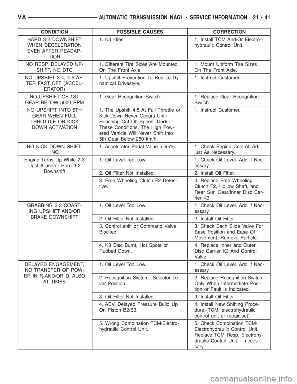
CONDITION POSSIBLE CAUSES CORRECTION
HARD 3-2 DOWNSHIFT
WHEN DECELERATION
EVEN AFTER READAP-
TION1. K3 Idles. 1. Install TCM And/Or Electro-
hydraulic Control Unit.
NO RESP. DELAYED UP-
SHIFT, NO DTC1. Different Tire Sizes Are Mounted
On The Front Axle.1. Mount Uniform Tire Sizes
On The Front Axle.
NO UPSHIFT 3-4, 4-5 AF-
TER FAST OFF (ACCEL-
ERATOR)1. Upshift Prevention To Realize Dy-
namical Drivestyle.1. Instruct Customer.
NO UPSHIFT OF 1ST
GEAR BELOW 5000 RPM1. Gear Recognition Switch. 1. Replace Gear Recognition
Switch.
NO UPSHIFT INTO 5TH
GEAR WHEN FULL
THROTTLE OR KICK
DOWN ACTIVATION1. The Upshift 4-5 At Full Throttle or
Kick Down Never Occurs Until
Reaching Cut Off Speed. Under
These Conditions, The High Pow-
ered Vehicle Will Never Shift Into
5th Gear Below 250 km/h.1. Instruct Customer.
NO KICK DOWN SHIFT-
ING1. Accelerator Pedal Value < 95%. 1. Check Engine Control. Ad-
just As Necessary.
Engine Turns Up While 2-3
Upshift and/or Hard 3-2
Downshift1. Oil Level Too Low. 1. Check Oil Level. Add if Nec-
essary.
2. Oil Filter Not Installed. 2. Install Oil Filter.
3. Free Wheeling Clutch F2 Defec-
tive.3. Replace Free Wheeling
Clutch F2, Hollow Shaft, and
Rear Sun Gear/Inner Disc Car-
rier K3.
GRABBING 2-3 COAST-
ING UPSHIFT AND/OR
BRAKE DOWNSHIFT1. Oil Level Too Low. 1. Check Oil Level. Add if Nec-
essary.
2. Oil Filter Not Installed. 2. Install Oil Filter.
3. Control shift or Command Valve
Blocked.3. Check Each Slide Valve For
Base Position and Ease Of
Movement, Remove Particle.
4. K3 Disc Burnt, Hot Spots or
Rubbed Down.4. Replace Inner and Outer
Disc Carrier K3 And Control
Valve.
DELAYED ENGAGEMENT,
NO TRANSFER OF POW-
ER IN R AND/OR D, ALSO
AT TIMES1. Oil Level Too Low. 1. Check Oil Level. Add if Nec-
essary.
2. Recognition Switch - Selector Le-
ver Position.2. Replace Recognition Switch
Only When Intermediate Posi-
tion or Fault is Indicated.
3. Oil Filter Not Installed. 3. Install Oil Filter.
4. AEV, Delayed Pressure Build Up
On Piston B2/B3.4. Install New Shifting Proce-
dure (TCM, electrohydraulic
control unit or repair set).
5. Wrong Combination TCM/Electro-
hydraulic Control Unit.5. Check Combination TCM/
Electrohydraulic Control Unit.
Replace TCM Resp. Electrohy-
draulic Control Unit, if neces-
sary.
VAAUTOMATIC TRANSMISSION NAG1 - SERVICE INFORMATION 21 - 41
Page 1787 of 2305
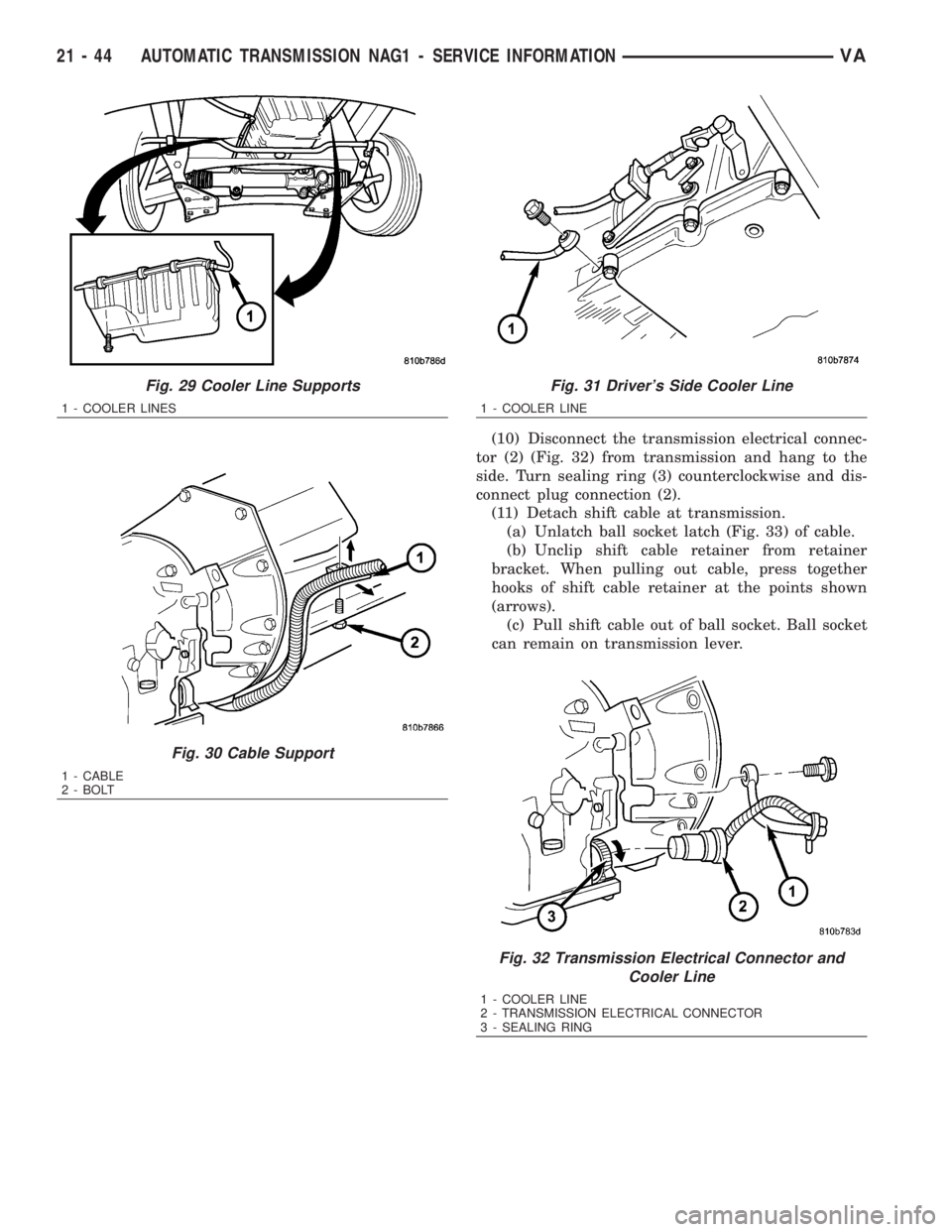
(10) Disconnect the transmission electrical connec-
tor (2) (Fig. 32) from transmission and hang to the
side. Turn sealing ring (3) counterclockwise and dis-
connect plug connection (2).
(11) Detach shift cable at transmission.
(a) Unlatch ball socket latch (Fig. 33) of cable.
(b) Unclip shift cable retainer from retainer
bracket. When pulling out cable, press together
hooks of shift cable retainer at the points shown
(arrows).
(c) Pull shift cable out of ball socket. Ball socket
can remain on transmission lever.
Fig. 29 Cooler Line Supports
1 - COOLER LINES
Fig. 30 Cable Support
1 - CABLE
2 - BOLT
Fig. 31 Driver's Side Cooler Line
1 - COOLER LINE
Fig. 32 Transmission Electrical Connector and
Cooler Line
1 - COOLER LINE
2 - TRANSMISSION ELECTRICAL CONNECTOR
3 - SEALING RING
21 - 44 AUTOMATIC TRANSMISSION NAG1 - SERVICE INFORMATIONVA
Page 1788 of 2305
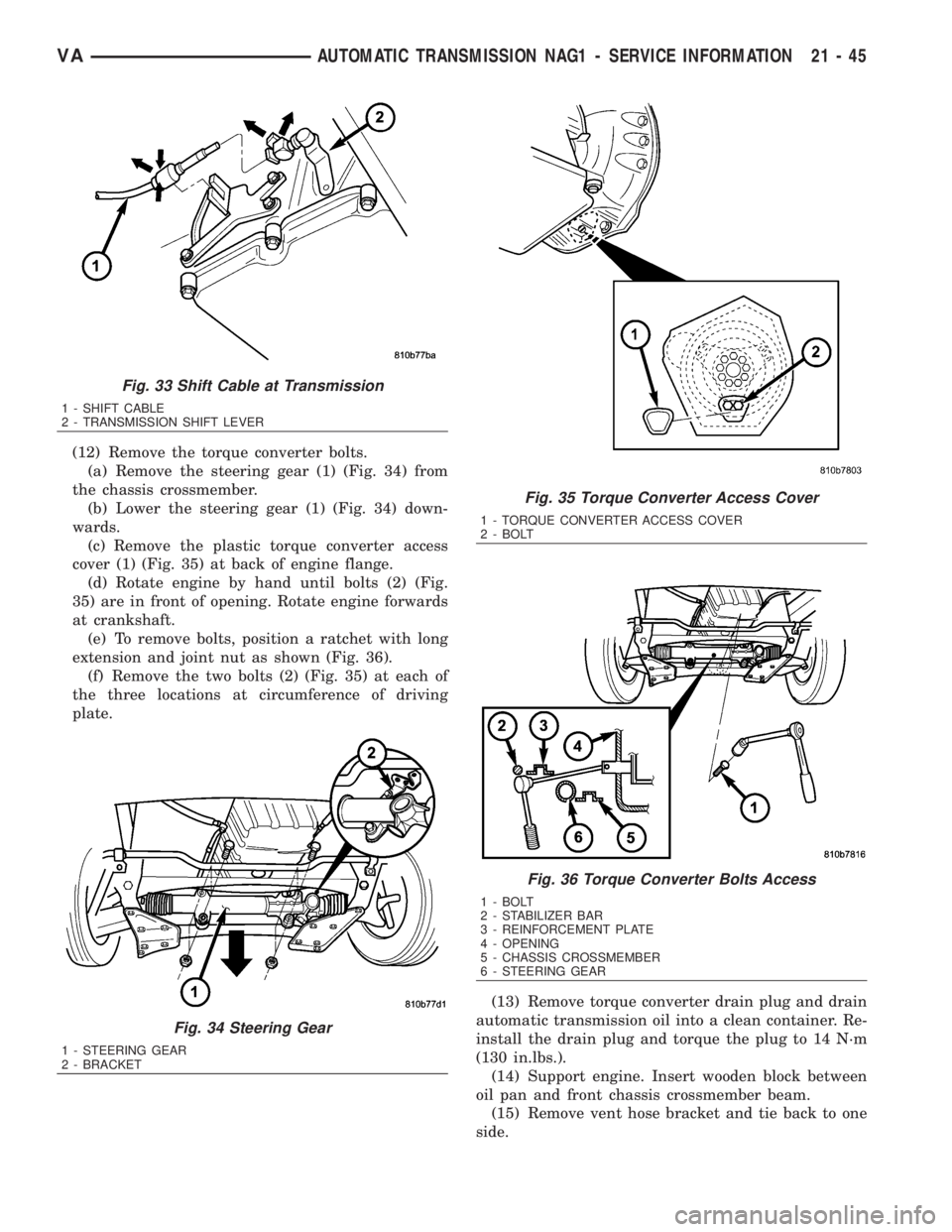
(12) Remove the torque converter bolts.
(a) Remove the steering gear (1) (Fig. 34) from
the chassis crossmember.
(b) Lower the steering gear (1) (Fig. 34) down-
wards.
(c) Remove the plastic torque converter access
cover (1) (Fig. 35) at back of engine flange.
(d) Rotate engine by hand until bolts (2) (Fig.
35) are in front of opening. Rotate engine forwards
at crankshaft.
(e) To remove bolts, position a ratchet with long
extension and joint nut as shown (Fig. 36).
(f) Remove the two bolts (2) (Fig. 35) at each of
the three locations at circumference of driving
plate.
(13) Remove torque converter drain plug and drain
automatic transmission oil into a clean container. Re-
install the drain plug and torque the plug to 14 N´m
(130 in.lbs.).
(14) Support engine. Insert wooden block between
oil pan and front chassis crossmember beam.
(15) Remove vent hose bracket and tie back to one
side.
Fig. 33 Shift Cable at Transmission
1 - SHIFT CABLE
2 - TRANSMISSION SHIFT LEVER
Fig. 34 Steering Gear
1 - STEERING GEAR
2 - BRACKET
Fig. 35 Torque Converter Access Cover
1 - TORQUE CONVERTER ACCESS COVER
2 - BOLT
Fig. 36 Torque Converter Bolts Access
1 - BOLT
2 - STABILIZER BAR
3 - REINFORCEMENT PLATE
4 - OPENING
5 - CHASSIS CROSSMEMBER
6 - STEERING GEAR
VAAUTOMATIC TRANSMISSION NAG1 - SERVICE INFORMATION 21 - 45
Page 1794 of 2305
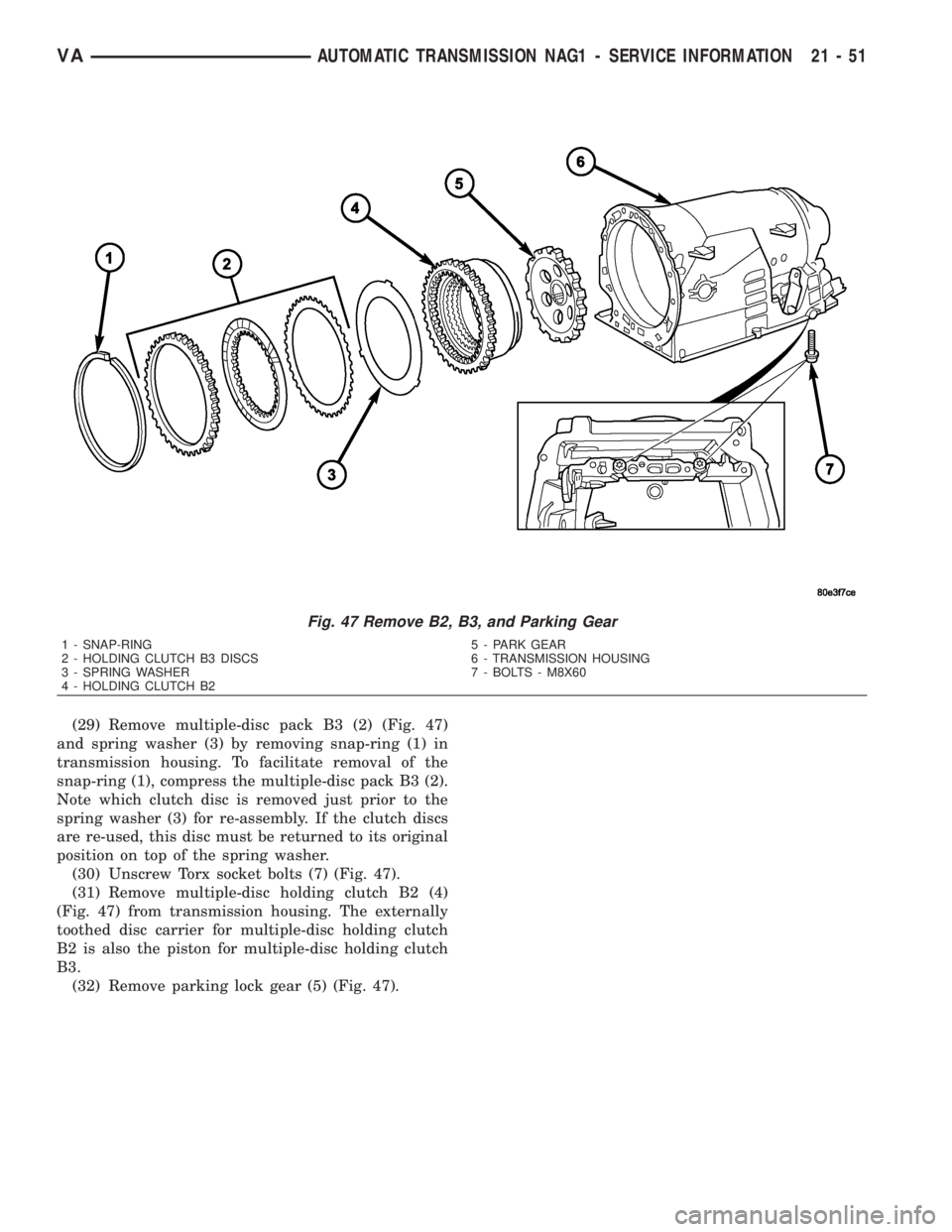
(29) Remove multiple-disc pack B3 (2) (Fig. 47)
and spring washer (3) by removing snap-ring (1) in
transmission housing. To facilitate removal of the
snap-ring (1), compress the multiple-disc pack B3 (2).
Note which clutch disc is removed just prior to the
spring washer (3) for re-assembly. If the clutch discs
are re-used, this disc must be returned to its original
position on top of the spring washer.
(30) Unscrew Torx socket bolts (7) (Fig. 47).
(31) Remove multiple-disc holding clutch B2 (4)
(Fig. 47) from transmission housing. The externally
toothed disc carrier for multiple-disc holding clutch
B2 is also the piston for multiple-disc holding clutch
B3.
(32) Remove parking lock gear (5) (Fig. 47).
Fig. 47 Remove B2, B3, and Parking Gear
1 - SNAP-RING 5 - PARK GEAR
2 - HOLDING CLUTCH B3 DISCS 6 - TRANSMISSION HOUSING
3 - SPRING WASHER 7 - BOLTS - M8X60
4 - HOLDING CLUTCH B2
VAAUTOMATIC TRANSMISSION NAG1 - SERVICE INFORMATION 21 - 51
Page 1795 of 2305
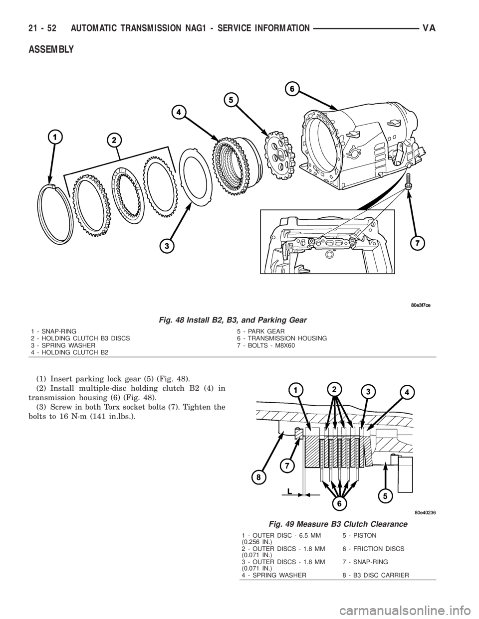
ASSEMBLY
(1) Insert parking lock gear (5) (Fig. 48).
(2) Install multiple-disc holding clutch B2 (4) in
transmission housing (6) (Fig. 48).
(3) Screw in both Torx socket bolts (7). Tighten the
bolts to 16 N´m (141 in.lbs.).
Fig. 48 Install B2, B3, and Parking Gear
1 - SNAP-RING 5 - PARK GEAR
2 - HOLDING CLUTCH B3 DISCS 6 - TRANSMISSION HOUSING
3 - SPRING WASHER 7 - BOLTS - M8X60
4 - HOLDING CLUTCH B2
Fig. 49 Measure B3 Clutch Clearance
1 - OUTER DISC - 6.5 MM
(0.256 IN.)5 - PISTON
2 - OUTER DISCS - 1.8 MM
(0.071 IN.)6 - FRICTION DISCS
3 - OUTER DISCS - 1.8 MM
(0.071 IN.)7 - SNAP-RING
4 - SPRING WASHER 8 - B3 DISC CARRIER
21 - 52 AUTOMATIC TRANSMISSION NAG1 - SERVICE INFORMATIONVA
Page 1800 of 2305
(18) Using grease, install both Teflon rings in the
groove at the rear of the output shaft so that the
joint stays together.
(19) Mount transmission housing on converter
housing.
(20) Screw in Torx socket bolts through the trans-
mission housing into the converter housing. Tighten
the bolts to 20 N´m (177 in.lbs.).
(21) Measure end-play between park pawl gear
and grooved ball bearing in order to select the proper
geartrain end-play shim.
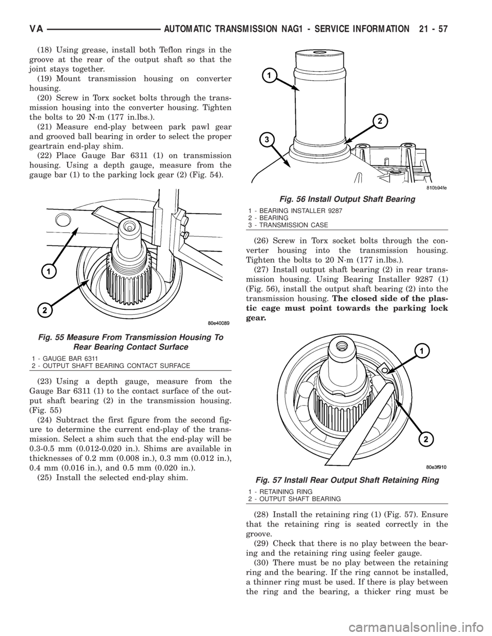
(22) Place Gauge Bar 6311 (1) on transmission
housing. Using a depth gauge, measure from the
gauge bar (1) to the parking lock gear (2) (Fig. 54).
(23) Using a depth gauge, measure from the
Gauge Bar 6311 (1) to the contact surface of the out-
put shaft bearing (2) in the transmission housing.
(Fig. 55)
(24) Subtract the first figure from the second fig-
ure to determine the current end-play of the trans-
mission. Select a shim such that the end-play will be
0.3-0.5 mm (0.012-0.020 in.). Shims are available in
thicknesses of 0.2 mm (0.008 in.), 0.3 mm (0.012 in.),
0.4 mm (0.016 in.), and 0.5 mm (0.020 in.).
(25) Install the selected end-play shim.(26) Screw in Torx socket bolts through the con-
verter housing into the transmission housing.
Tighten the bolts to 20 N´m (177 in.lbs.).
(27) Install output shaft bearing (2) in rear trans-
mission housing. Using Bearing Installer 9287 (1)
(Fig. 56), install the output shaft bearing (2) into the
transmission housing.The closed side of the plas-
tic cage must point towards the parking lock
gear.
(28) Install the retaining ring (1) (Fig. 57). Ensure
that the retaining ring is seated correctly in the
groove.
(29) Check that there is no play between the bear-
ing and the retaining ring using feeler gauge.
(30) There must be no play between the retaining
ring and the bearing. If the ring cannot be installed,
a thinner ring must be used. If there is play between
the ring and the bearing, a thicker ring must be
Fig. 55 Measure From Transmission Housing To
Rear Bearing Contact Surface
1 - GAUGE BAR 6311
2 - OUTPUT SHAFT BEARING CONTACT SURFACE
Fig. 56 Install Output Shaft Bearing
1 - BEARING INSTALLER 9287
2 - BEARING
3 - TRANSMISSION CASE
Fig. 57 Install Rear Output Shaft Retaining Ring
1 - RETAINING RING
2 - OUTPUT SHAFT BEARING
VAAUTOMATIC TRANSMISSION NAG1 - SERVICE INFORMATION 21 - 57
Page 1804 of 2305
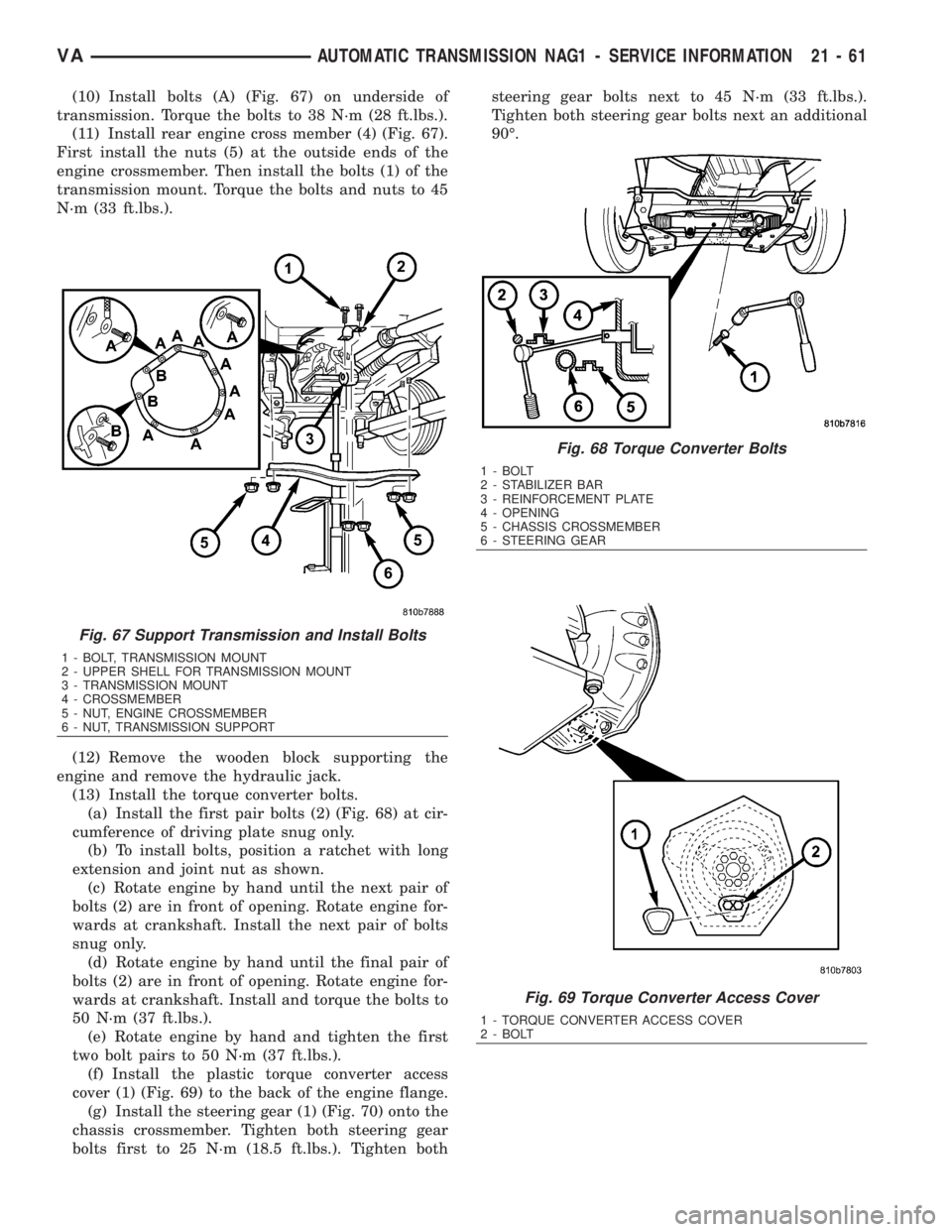
(10) Install bolts (A) (Fig. 67) on underside of
transmission. Torque the bolts to 38 N´m (28 ft.lbs.).
(11) Install rear engine cross member (4) (Fig. 67).
First install the nuts (5) at the outside ends of the
engine crossmember. Then install the bolts (1) of the
transmission mount. Torque the bolts and nuts to 45
N´m (33 ft.lbs.).
(12) Remove the wooden block supporting the
engine and remove the hydraulic jack.
(13) Install the torque converter bolts.
(a) Install the first pair bolts (2) (Fig. 68) at cir-
cumference of driving plate snug only.
(b) To install bolts, position a ratchet with long
extension and joint nut as shown.
(c) Rotate engine by hand until the next pair of
bolts (2) are in front of opening. Rotate engine for-
wards at crankshaft. Install the next pair of bolts
snug only.
(d) Rotate engine by hand until the final pair of
bolts (2) are in front of opening. Rotate engine for-
wards at crankshaft. Install and torque the bolts to
50 N´m (37 ft.lbs.).
(e) Rotate engine by hand and tighten the first
two bolt pairs to 50 N´m (37 ft.lbs.).
(f) Install the plastic torque converter access
cover (1) (Fig. 69) to the back of the engine flange.
(g) Install the steering gear (1) (Fig. 70) onto the
chassis crossmember. Tighten both steering gear
bolts first to 25 N´m (18.5 ft.lbs.). Tighten bothsteering gear bolts next to 45 N´m (33 ft.lbs.).
Tighten both steering gear bolts next an additional
90É.
Fig. 67 Support Transmission and Install Bolts
1 - BOLT, TRANSMISSION MOUNT
2 - UPPER SHELL FOR TRANSMISSION MOUNT
3 - TRANSMISSION MOUNT
4 - CROSSMEMBER
5 - NUT, ENGINE CROSSMEMBER
6 - NUT, TRANSMISSION SUPPORT
Fig. 68 Torque Converter Bolts
1 - BOLT
2 - STABILIZER BAR
3 - REINFORCEMENT PLATE
4 - OPENING
5 - CHASSIS CROSSMEMBER
6 - STEERING GEAR
Fig. 69 Torque Converter Access Cover
1 - TORQUE CONVERTER ACCESS COVER
2 - BOLT
VAAUTOMATIC TRANSMISSION NAG1 - SERVICE INFORMATION 21 - 61