2006 MERCEDES-BENZ SPRINTER lock
[x] Cancel search: lockPage 1701 of 2305
INSTALLATION
CAUTION: Whenever the fuel pump module is ser-
viced, the rubber gasket must be replaced.
(1) Thoroughly clean locknut (lockring) and lock-
nut threads at top of tank.
(2) Position new gasket (seal) to fuel tank opening.
(3) Position float rod assembly partially into fuel
tank.
(4) Position fuel pump module partially into fuel
tank.
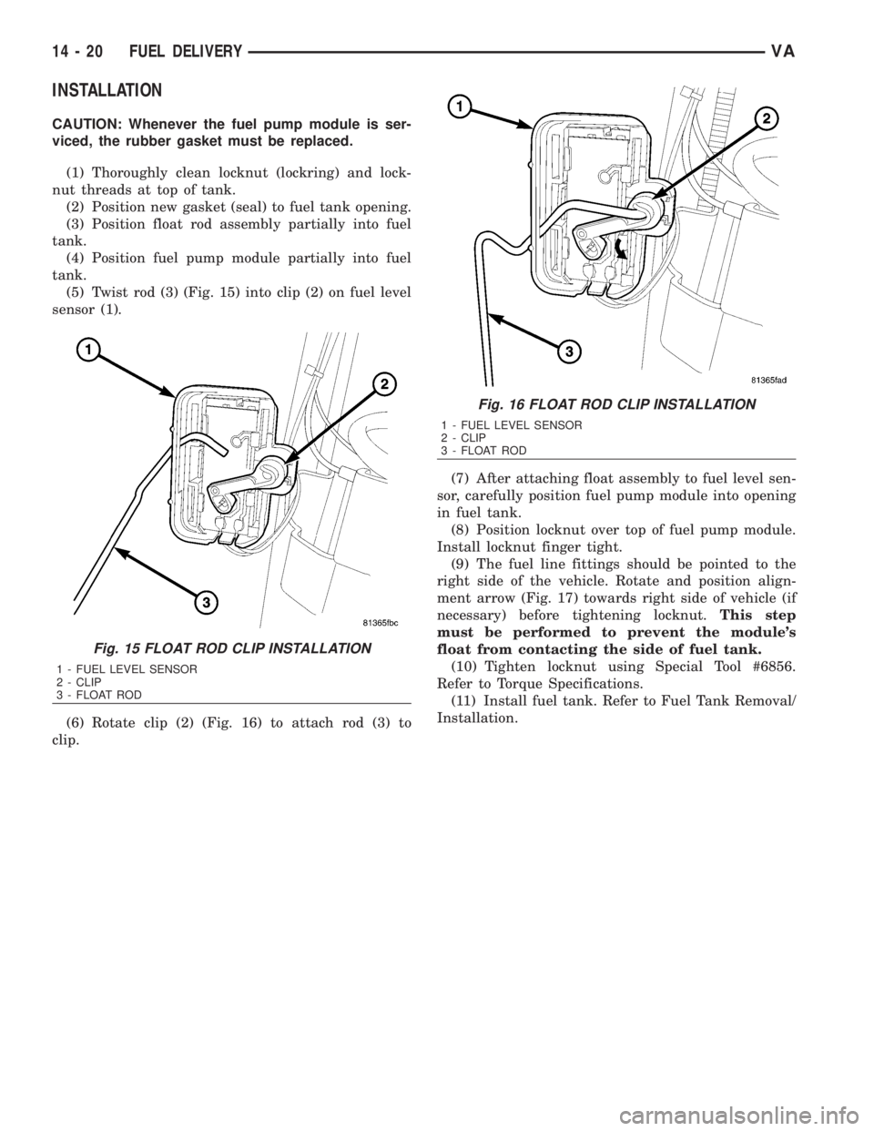
(5) Twist rod (3) (Fig. 15) into clip (2) on fuel level
sensor (1).
(6) Rotate clip (2) (Fig. 16) to attach rod (3) to
clip.(7) After attaching float assembly to fuel level sen-
sor, carefully position fuel pump module into opening
in fuel tank.
(8) Position locknut over top of fuel pump module.
Install locknut finger tight.
(9) The fuel line fittings should be pointed to the
right side of the vehicle. Rotate and position align-
ment arrow (Fig. 17) towards right side of vehicle (if
necessary) before tightening locknut.This step
must be performed to prevent the module's
float from contacting the side of fuel tank.
(10) Tighten locknut using Special Tool #6856.
Refer to Torque Specifications.
(11) Install fuel tank. Refer to Fuel Tank Removal/
Installation.
Fig. 15 FLOAT ROD CLIP INSTALLATION
1 - FUEL LEVEL SENSOR
2 - CLIP
3 - FLOAT ROD
Fig. 16 FLOAT ROD CLIP INSTALLATION
1 - FUEL LEVEL SENSOR
2 - CLIP
3 - FLOAT ROD
14 - 20 FUEL DELIVERYVA
Page 1702 of 2305
FUEL QUANTITY CONTROL
VA LV E
DESCRIPTION
The fuel quantity control valve mounts to front of
the high pressure pump and is controlled by the
ECM. The quantity control valve assists in maintain-
ing proper fuel quantity injected under all operating
conditions. Fuel tank heat protection is also provided
by the quantity control valve. The valve meters the
exact amount of fuel to prevent excess heated fuel
from returning to the tank.
OPERATION
The ECM monitors the fuel system and measures
for pressure vibrations. The ECM will then send a
pulse width signal to the quantity control valve to
regulate the amount of fuel to the high pressure
pump plunger and barrel assemblies. The valve then
adjusts the injection correction quantity for each
individual cylinder in line with the firing order, there
by eliminating the pressure resonance in the fuel rail
and improving each independent injectors operation.
The fuel quantity valve also interrupts the fuel sup-
ply to the high pressure pump plunger and barrel
assemblies when the engine is switched off.
The ECM detects the operating state which exists
at the engine by means of the sensors. In order to
adapt the quantity injected, either the rail pressure
can be adjusted by way of the pressure regulator
valve and the quantity control valve, or the actuationtime of the solenoid valves in the fuel injectors can
be extended or shortened.
Fuel quantity control is performed under the fol-
lowing operating conditions:
²Approximately 30 seconds after the engine has
started
²Fuel temperature > 20ÉC (68ÉF)
²Engine not in deceleration mode
REMOVAL
(1) Disconnect the negative battery cable.
(2) Disconnect the control valve wiring harness
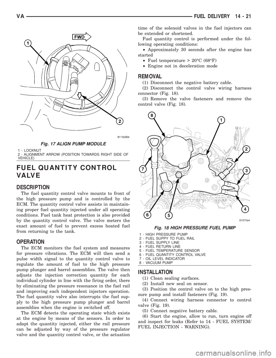
connector (Fig. 18).
(3) Remove the valve fasteners and remove the
control valve (Fig. 18).
INSTALLATION
(1) Clean sealing surfaces.
(2) Install new seal on sensor.
(3) Position the control valve on to the high pres-
sure pump and install fasteners (Fig. 19).
(4) Connect wiring harness connector to control
valve (Fig. 19).
(5) Connect negative battery cable.
(6) Start the engine, allow to run, turn engine off
and inspect for leaks (Refer to 14 - FUEL SYSTEM/
FUEL INJECTION - WARNING).
Fig. 17 ALIGN PUMP MODULE
1 - LOCKNUT
2 - ALIGNMENT ARROW (POSITION TOWARDS RIGHT SIDE OF
VEHICLE)
Fig. 18 HIGH PRESSURE FUEL PUMP
1 - HIGH PRESSURE PUMP
2 - FUEL SUPPY TO FUEL RAIL
3 - FUEL SUPPLY LINE
4 - FUEL RETURN LINE
5 - FUEL TEMPERATURE SENSOR
6 - FUEL QUANTITY CONTROL VALVE
7 - OIL LEVEL INDICATOR
8 - VACUUM PUMP
VAFUEL DELIVERY 14 - 21
Page 1706 of 2305
REMOVAL
(1) Drain diesel fuel from tank. Refer to Standard
Procedure Ð Draining Fuel Tank Ð Diesel.
(2) Disconnect fuel fill and vent lines from body.
(3) Raise and support vehicle.
(4) Support tank with a hydraulic jack.
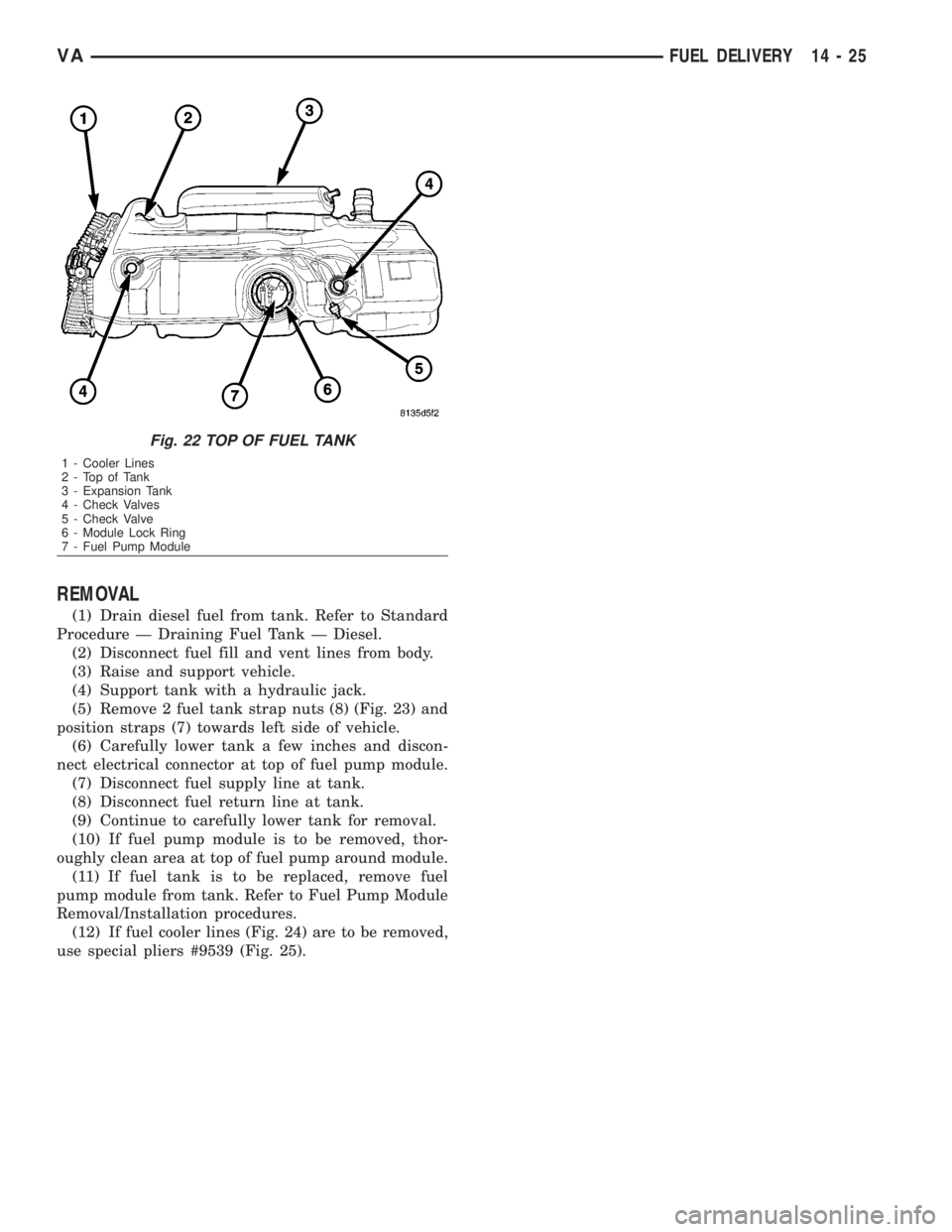
(5) Remove 2 fuel tank strap nuts (8) (Fig. 23) and
position straps (7) towards left side of vehicle.
(6) Carefully lower tank a few inches and discon-
nect electrical connector at top of fuel pump module.
(7) Disconnect fuel supply line at tank.
(8) Disconnect fuel return line at tank.
(9) Continue to carefully lower tank for removal.
(10) If fuel pump module is to be removed, thor-
oughly clean area at top of fuel pump around module.
(11) If fuel tank is to be replaced, remove fuel
pump module from tank. Refer to Fuel Pump Module
Removal/Installation procedures.
(12) If fuel cooler lines (Fig. 24) are to be removed,
use special pliers #9539 (Fig. 25).
Fig. 22 TOP OF FUEL TANK
1 - Cooler Lines
2-TopofTank
3 - Expansion Tank
4 - Check Valves
5 - Check Valve
6 - Module Lock Ring
7 - Fuel Pump Module
VAFUEL DELIVERY 14 - 25
Page 1710 of 2305
a variable resistor track (card).
REMOVAL
The fuel level sending unit (fuel level sensor) and
float assembly is located on the side of the fuel pump
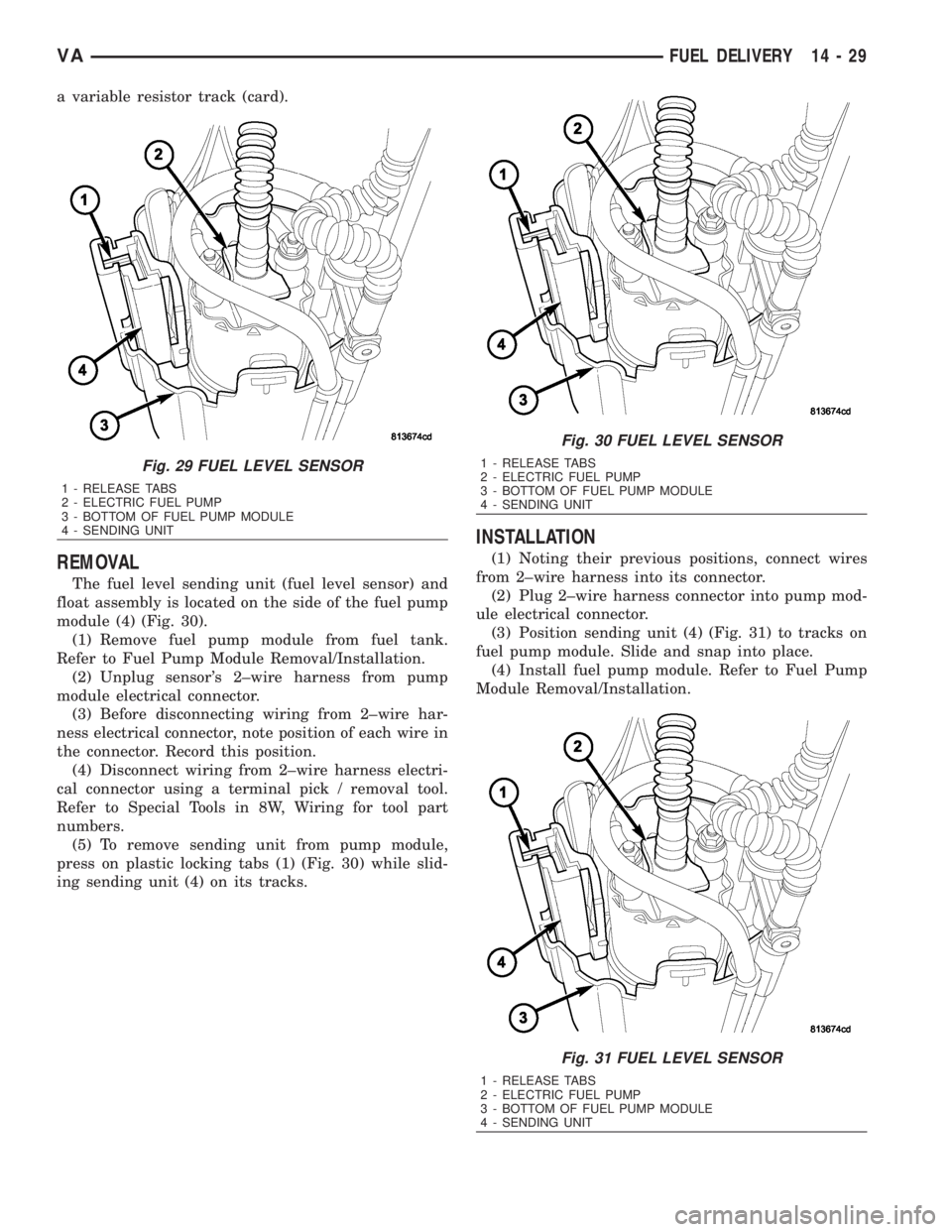
module (4) (Fig. 30).
(1) Remove fuel pump module from fuel tank.
Refer to Fuel Pump Module Removal/Installation.
(2) Unplug sensor's 2±wire harness from pump
module electrical connector.
(3) Before disconnecting wiring from 2±wire har-
ness electrical connector, note position of each wire in
the connector. Record this position.
(4) Disconnect wiring from 2±wire harness electri-
cal connector using a terminal pick / removal tool.
Refer to Special Tools in 8W, Wiring for tool part
numbers.
(5) To remove sending unit from pump module,
press on plastic locking tabs (1) (Fig. 30) while slid-
ing sending unit (4) on its tracks.
INSTALLATION
(1) Noting their previous positions, connect wires
from 2±wire harness into its connector.
(2) Plug 2±wire harness connector into pump mod-
ule electrical connector.
(3) Position sending unit (4) (Fig. 31) to tracks on
fuel pump module. Slide and snap into place.
(4) Install fuel pump module. Refer to Fuel Pump
Module Removal/Installation.
Fig. 29 FUEL LEVEL SENSOR
1 - RELEASE TABS
2 - ELECTRIC FUEL PUMP
3 - BOTTOM OF FUEL PUMP MODULE
4 - SENDING UNIT
Fig. 30 FUEL LEVEL SENSOR
1 - RELEASE TABS
2 - ELECTRIC FUEL PUMP
3 - BOTTOM OF FUEL PUMP MODULE
4 - SENDING UNIT
Fig. 31 FUEL LEVEL SENSOR
1 - RELEASE TABS
2 - ELECTRIC FUEL PUMP
3 - BOTTOM OF FUEL PUMP MODULE
4 - SENDING UNIT
VAFUEL DELIVERY 14 - 29
Page 1716 of 2305
(3) Install engine cover.
(4) Reconnect negative battery cable.
CRANKSHAFT POSITION SEN-
SOR
DESCRIPTION
The crankshaft position sensor is located opposite
the teeth on the flywheel and uses a non contact
method to record the position of the crankshaft. The
leading edges of each tooth on the flywheel generate
a positive signal in the position sensor, while the
trailing edges generate a negative signal. When the
crankshaft is rotating, an alternating voltage is pro-
duced as a result.
The period of the signal is the time required by the
crankshaft to turn through the gap between two fly-
wheel teeth. The clearance between the crankshaft
position sensor and the teeth of the flywheel is fixed
by the installation.
Two teeth on the flywheel are missing. The result-
ing signal gap is used by the ECM to detect the TDC
position of cylinder number one.
OPERATION
The clearance between the crankshaft position sen-
sor and the flywheel are fixed by the installation
position. Two teeth on the flywheel are missing. The
resulting gap is used by the ECM to detect DTC of
cylinder number one. The crankshaft position is cal-
culated to an accuracy of a fraction of a degree so
that the start and end of injection can occur at
exactly the right moment. The engine speed signal is
also processed by the ECM from the crankshaft sen-
sor. This signal is then transferred to other control
modules over the CAN bus.
If the crankshaft position sensor fails, the ECM
will stop triggering the injectors, the engine will
stall, the engine warning light may or may not illu-
minate, but the engine will not restart.
REMOVAL
(1) Disconnect the negative battery cable.
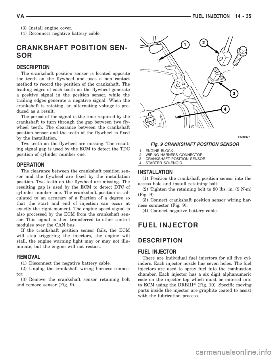
(2) Unplug the crankshaft wiring harness connec-
tor.
(3) Remove the crankshaft sensor retaining bolt
and remove sensor (Fig. 9).
INSTALLATION
(1) Position the crankshaft position sensor into the
access hole and install retaining bolt.
(2) Tighten the retaining bolt to 80 lbs. in. (9 N´m)
(Fig. 9).
(3) Connect crankshaft position sensor wiring har-
ness connector (Fig. 9).
(4) Connect negative battery cable.
FUEL INJECTOR
DESCRIPTION
FUEL INJECTOR
There are individual fuel injectors for all five cyl-
inders. Each injector nozzle has seven holes. The fuel
injectors are used to spray fuel into the combustion
chamber. Each injector has a six digit alphanumeric
code on the injector top which must be entered into
to ECM using the DRBIIIt(Fig. 10). Specific moving
parts inside the injector are graphite coated to assist
with the lubrication process.
Fig. 9 CRANKSHAFT POSITION SENSOR
1 - ENGINE BLOCK
2 - WIRING HARNESS CONNECTOR
3 - CRANKSHAFT POSITION SENSOR
4 - STARTER SOLENOID
VAFUEL INJECTION 14 - 35
Page 1719 of 2305
INJECTOR CLASSIFICATION PROCEDURE
(1) Turn ignition switch ªONº.
(2) Using a DRB IIItand select ENGINE then
MISCELLANEOUS.
(3) Select LEARN INJECTORS.
(4) Using the up and down arrows, scroll to the
appropriate injector.
(5) Using the right and left arrows, set injector to
proper classification.
(6) Once injectors are classified, cycle ignition to
complete.
CLEANING FUEL INJECTORS
NOTE: Before cleaning the injector recesses, seal
the injector holes in the injector recesses with the
appropriate pin to prevent debris from falling into
the recesses and entering the motor.
(1) Seal the injector holes inside the cylinder head
recesses.
(2) Wipe out injector recesses with a non-woven
cloth, then clean with a cylinder brush.
(3) Clean the bottom of the cylinder recess with a
round brush.
(4) Blow out the recess and clean again with a
non-woven cloth and cover over.
(5) Perform these steps for each injector recess.
NOTE: DO NOT clean the tip of the injector with a
wire brush. Use a non - woven cloth.
(6) Clean injector body with a wire brush.
(7) Clean injector tips with a non-woven cloth.
NOTE: Do Not apply antiseize lubricant to the injec-
tor nozzle area.
(8) Grease injector body with anti seize lubricant.
NOTE: Always replace the seals that seal off the
injectors at the cylinder head to the combustion
chamber and replace the retaining screws.
REMOVAL
WARNING: NO SPARKS, OPEN FLAMES OR SMOK-
ING. RISK OF POISONING FROM INHALING AND
SWALLOWING FUEL. RISK OF INJURY TO EYES
AND SKIN FROM CONTACT WITH FUEL. POUR
FUELS ONLY INTO SUITABLE AND APPROPRI-
ATELY MARKED CONTAINERS. WEAR PROTECTIVE
CLOTHING.
NOTE: When removing injectors, the seal rings and
retaining stretch bolts must always be replaced.
Coat the injector body with the anti-seize com-pound before installing. Keep lubricant away from
the injector nozzle.
(1) Disconnect negative battery cable.
(2) Remove engine cover (Refer to 9 - ENGINE -
REMOVAL).
(3) Remove the fuel return hose locking clamps at
the injector and remove return hose.
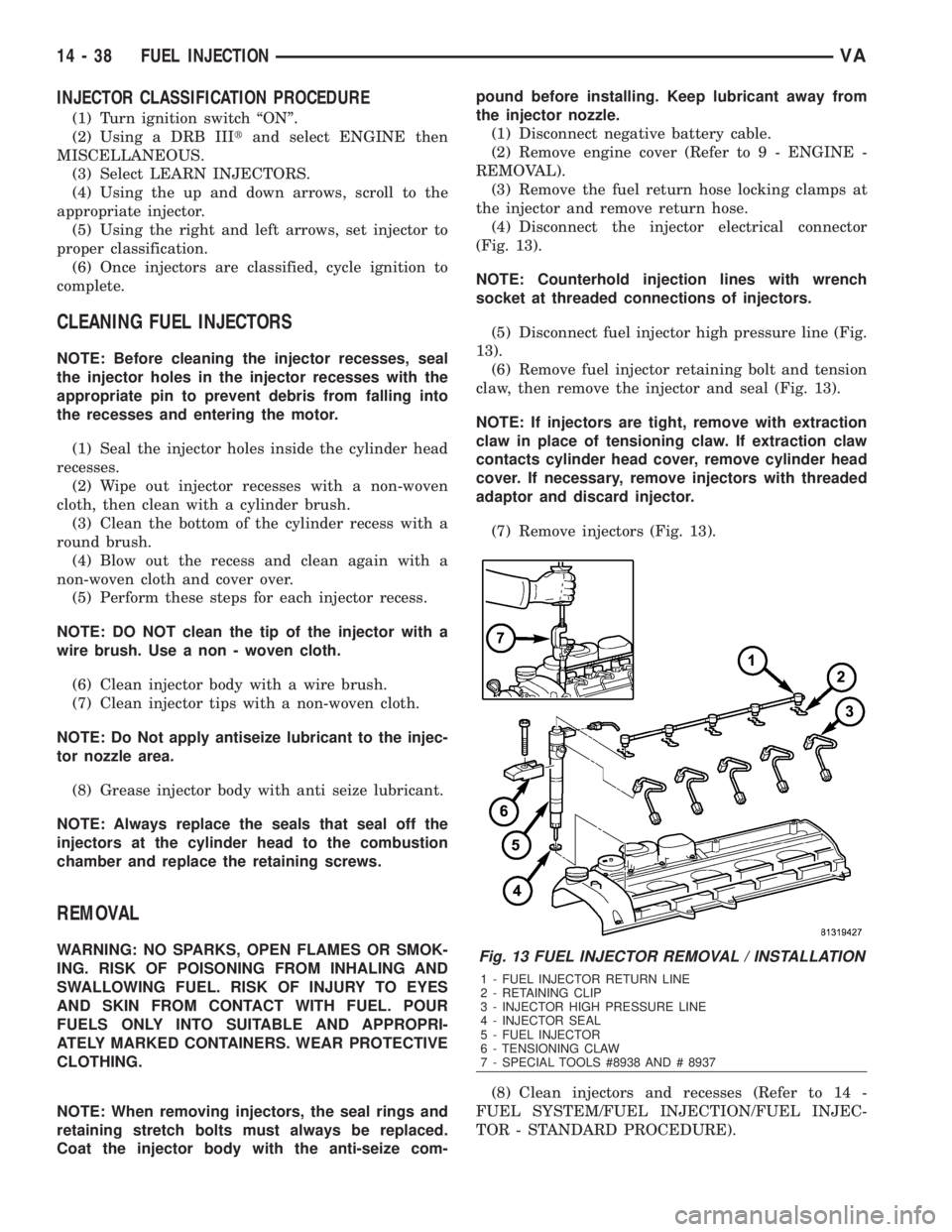
(4) Disconnect the injector electrical connector
(Fig. 13).
NOTE: Counterhold injection lines with wrench
socket at threaded connections of injectors.
(5) Disconnect fuel injector high pressure line (Fig.
13).
(6) Remove fuel injector retaining bolt and tension
claw, then remove the injector and seal (Fig. 13).
NOTE: If injectors are tight, remove with extraction
claw in place of tensioning claw. If extraction claw
contacts cylinder head cover, remove cylinder head
cover. If necessary, remove injectors with threaded
adaptor and discard injector.
(7) Remove injectors (Fig. 13).
(8) Clean injectors and recesses (Refer to 14 -
FUEL SYSTEM/FUEL INJECTION/FUEL INJEC-
TOR - STANDARD PROCEDURE).Fig. 13 FUEL INJECTOR REMOVAL / INSTALLATION
1 - FUEL INJECTOR RETURN LINE
2 - RETAINING CLIP
3 - INJECTOR HIGH PRESSURE LINE
4 - INJECTOR SEAL
5 - FUEL INJECTOR
6 - TENSIONING CLAW
7 - SPECIAL TOOLS #8938 AND # 8937
14 - 38 FUEL INJECTIONVA
Page 1720 of 2305
INSTALLATION
WARNING: NO SPARKS, OPEN FLAMES OR SMOK-
ING. RISK OF POISONING FROM INHALING AND
SWALLOWING FUEL. RISK OF INJURY TO EYES
AND SKIN FROM CONTACT WITH FUEL. POUR
FUELS ONLY INTO SUITABLE AND APPROPRI-
ATELY MARKED CONTAINERS. WEAR PROTECTIVE
CLOTHING.
NOTE: When removing injectors, the seal rings and
retaining stretch bolts must always be replaced.
Coat the injector body with the anti-seize com-
pound before installing. Keep lubricant away from
the injector nozzle.
(1) Clean injectors and recesses (Refer to 14 -
FUEL SYSTEM/FUEL INJECTION/FUEL INJEC-
TOR - STANDARD PROCEDURE).
(2) Coat injector body with anti seize lubricant
then install injectors with new seals.
(3) Install tensioning claws with new screws at
injectors. Tighten screws in two stages, 7 N´m (62
lbs. in.) then 90É (Fig. 13).
NOTE: If locking clamp has been pulled off at injec-
tor, the locking clamp must be replaced.
(4) Position fuel return line at injectors and secure
locking clamps (Fig. 13).
NOTE: Counterhold injection lines with wrench
socket at threaded connections of injectors. DO
NOT over tighten.
(5) Install high pressure injection lines (Refer to
14 - FUEL SYSTEM/FUEL DELIVERY/FUEL LINES
- INSTALLATION).
(6) Reconnect injector electrical connectors (Fig.
13).
(7) Connect negative battery cable.
NOTE: Fuel Injectors have different flow rates.
When injectors are removed, re-enter all injector six
digit codes.
(8) Program all injector codes into the ECM using
the scan tool.
(9) Start engine, allow to run, turn engine off and
inspect for leaks (Refer to 14 - FUEL SYSTEM -
WARNING).
CAUTION: Care must be taken when installing the
engine cover. Assure the proper routing of the fuel
injector return fuel hose to the banjo bolt fitting in
the left rear corner of the cover. Failure to do so
may pinch or damage the hose causing fuel leakage
or a driveability concern.(10) Install engine cover (Refer to 9 - ENGINE -
INSTALLATION)..
FUEL PRESSURE SENSOR
DESCRIPTION
The fuel rail pressure sensor measures the current
fuel rail pressure and supplies an appropriate voltage
signal to the ECM. The non-constant fuel system
pressure influences the position of the internal dia-
phragm. This results in a variation in the electrical
resistance which is analyzed by the ECM.
OPERATION
The fuel rail pressure sensor measures the current
fuel rail pressure and sends a voltage signal to the
ECM. The ECM then actuates the fuel rail pressure
control valve until the desired rail pressure is
achieved.
REMOVAL
(1) (Refer to 14 - FUEL SYSTEM/FUEL INJEC-
TION - WARNING) Disconnect the negative battery
cable.
(2) Remove the mixing housing.
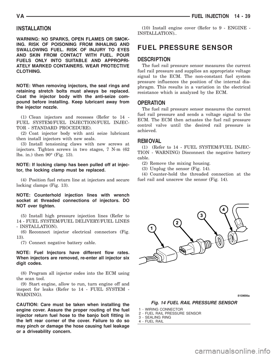
(3) Unplug the sensor (Fig. 14).
(4) Counter-hold the threaded connection at the
fuel rail and unscrew the sensor (Fig. 14).
Fig. 14 FUEL RAIL PRESSURE SENSOR
1 - WIRING CONNECTOR
2 - FUEL RAIL PRESSURE SENSOR
3 - SEALING RING
4 - FUEL RAIL
VAFUEL INJECTION 14 - 39
Page 1724 of 2305
OPERATION
The Negative Temperature Coefficient (NTC)
resister located within the intake air temperature
sensor alters it's resistance in line with the charge
air temperature. If the engine is cold, the value
equals ambient temperature. For a temperature of
68ÉF (20ÉC) the resistance is approximately 6000
ohms. For a temperature of 104ÉF (40ÉC) the resis-
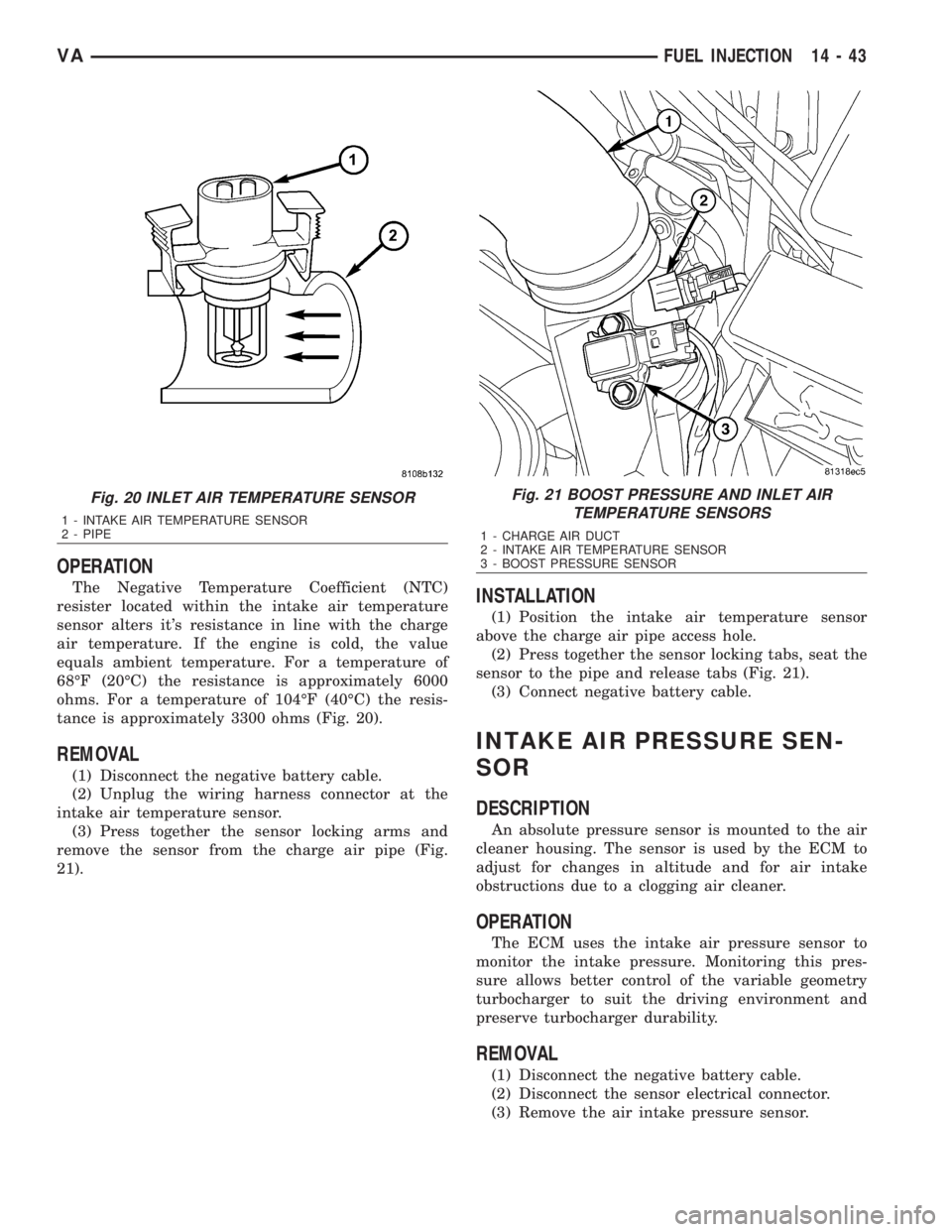
tance is approximately 3300 ohms (Fig. 20).
REMOVAL
(1) Disconnect the negative battery cable.
(2) Unplug the wiring harness connector at the
intake air temperature sensor.
(3) Press together the sensor locking arms and
remove the sensor from the charge air pipe (Fig.
21).
INSTALLATION
(1) Position the intake air temperature sensor
above the charge air pipe access hole.
(2) Press together the sensor locking tabs, seat the
sensor to the pipe and release tabs (Fig. 21).
(3) Connect negative battery cable.
INTAKE AIR PRESSURE SEN-
SOR
DESCRIPTION
An absolute pressure sensor is mounted to the air
cleaner housing. The sensor is used by the ECM to
adjust for changes in altitude and for air intake
obstructions due to a clogging air cleaner.
OPERATION
The ECM uses the intake air pressure sensor to
monitor the intake pressure. Monitoring this pres-
sure allows better control of the variable geometry
turbocharger to suit the driving environment and
preserve turbocharger durability.
REMOVAL
(1) Disconnect the negative battery cable.
(2) Disconnect the sensor electrical connector.
(3) Remove the air intake pressure sensor.
Fig. 20 INLET AIR TEMPERATURE SENSOR
1 - INTAKE AIR TEMPERATURE SENSOR
2 - PIPE
Fig. 21 BOOST PRESSURE AND INLET AIR
TEMPERATURE SENSORS
1 - CHARGE AIR DUCT
2 - INTAKE AIR TEMPERATURE SENSOR
3 - BOOST PRESSURE SENSOR
VAFUEL INJECTION 14 - 43