2006 MERCEDES-BENZ SPRINTER lock
[x] Cancel search: lockPage 1620 of 2305
PISTON & CONNECTING ROD
DESCRIPTION
NOTE: No over sized pistons are available.
The pistons are of a free floating design and made
of optimized aluminum alloy with a graphite coated
bearing surface. The crown of the piston has been
designed to accommodate higher injection pressures.
Oil jets in the engine block lubricate and cool the pis-
ton and pin assembly. The connecting rods have a
pressed in place wrist pin bushing featuring specially
adjusted lubrication grooves which are lubricated by
the oil jets (Fig. 37). The steel connecting rods fea-
ture a small end of trapezoidal shape and a cracked
large end.
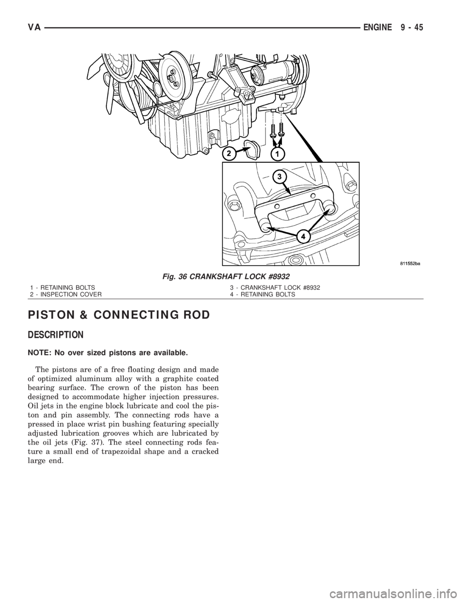
Fig. 36 CRANKSHAFT LOCK #8932
1 - RETAINING BOLTS 3 - CRANKSHAFT LOCK #8932
2 - INSPECTION COVER 4 - RETAINING BOLTS
VAENGINE 9 - 45
Page 1621 of 2305
STANDARD PROCEDURE
STANDARD PROCEDURE - CHECKING AND
REPAIRING CONNECTING RODS
NOTE: Connecting rods with blue discoloration,
cross scores or notches must be replaced. Com-
pensate for different weights by milling off the bal-
ancing weight.
(1) Inspect connecting rod for discoloring, cross
scores and notches.
NOTE: Connecting rod and bearing cap are marked
in sets and attached with two sleeves.
(2) Bolt connecting rod bearing cap to connecting
rod. Tighten connecting rod bearing caps to initialspecification (Refer to 9 - ENGINE/ENGINE BLOCK/
PISTON & CONNECTING ROD - INSTALLATION).
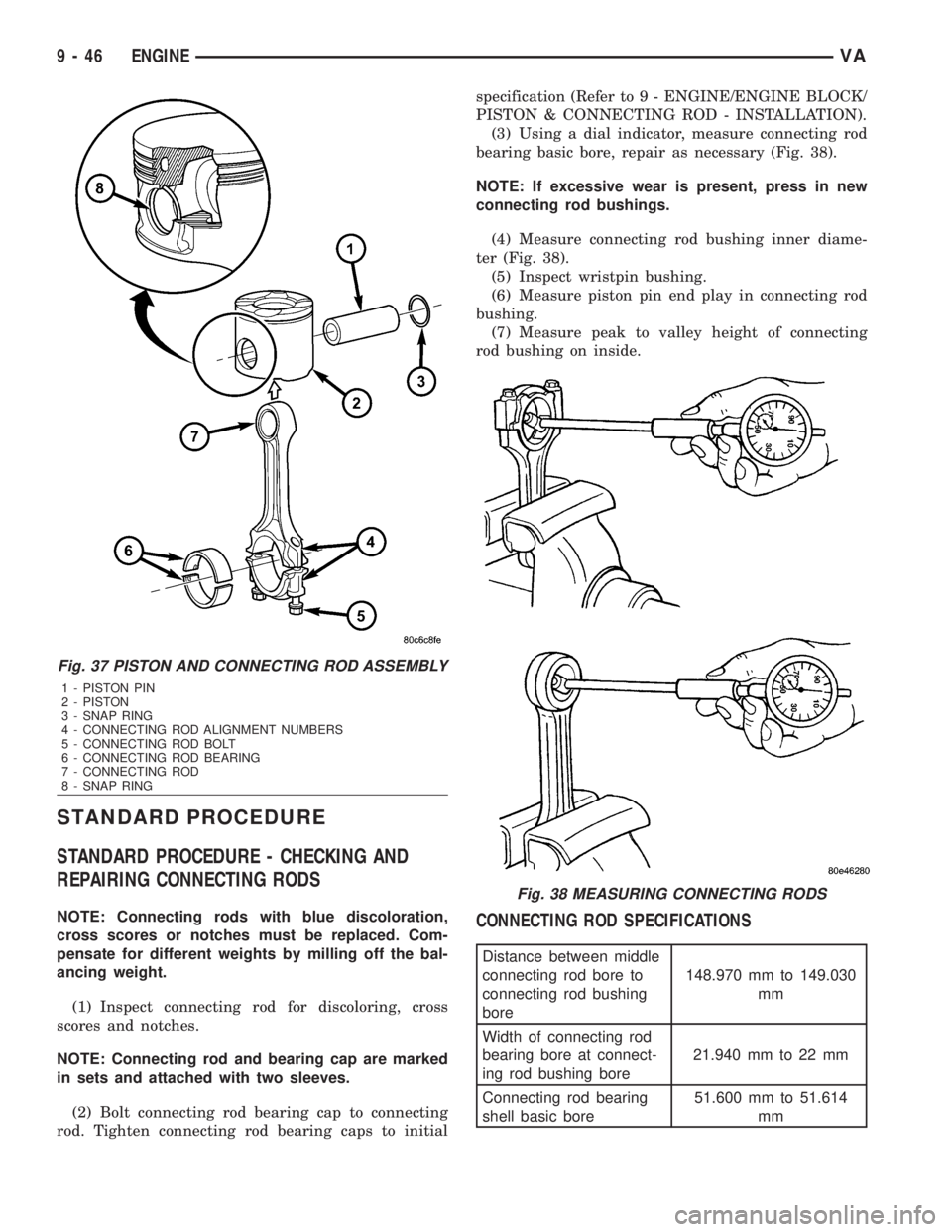
(3) Using a dial indicator, measure connecting rod
bearing basic bore, repair as necessary (Fig. 38).
NOTE: If excessive wear is present, press in new
connecting rod bushings.
(4) Measure connecting rod bushing inner diame-
ter (Fig. 38).
(5) Inspect wristpin bushing.
(6) Measure piston pin end play in connecting rod
bushing.
(7) Measure peak to valley height of connecting
rod bushing on inside.CONNECTING ROD SPECIFICATIONS
Distance between middle
connecting rod bore to
connecting rod bushing
bore148.970 mm to 149.030
mm
Width of connecting rod
bearing bore at connect-
ing rod bushing bore21.940 mm to 22 mm
Connecting rod bearing
shell basic bore51.600 mm to 51.614
mm
Fig. 37 PISTON AND CONNECTING ROD ASSEMBLY
1 - PISTON PIN
2 - PISTON
3 - SNAP RING
4 - CONNECTING ROD ALIGNMENT NUMBERS
5 - CONNECTING ROD BOLT
6 - CONNECTING ROD BEARING
7 - CONNECTING ROD
8 - SNAP RING
Fig. 38 MEASURING CONNECTING RODS
9 - 46 ENGINEVA
Page 1622 of 2305
Distance between middle
connecting rod bore to
connecting rod bushing
bore148.970 mm to 149.030
mm
Allowable out-of-round-
ness and taper of basic
bore.020 mm
Allowable twist of con-
necting rod bearing bore
to connecting rod bush-
ing bore over a length of
100 mm.100 mm
Allowable variation of
axial parallelism of con-
necting rod bearing bore
to connecting rod bush-
ing bore over a length of
100 mm.045 mm
Allowable difference in
weight of complete con-
necting rod of an engine2g
Connecting rod inner
bushing30.018 to 30.024 mm
Connecting rod outer
bushing32.575 mm to 32.600
mm
Connecting rod basic
bore32.500 mm to 32.525
mm
Piston pin play in con-
necting rod.018 mm to.024 mm
Peak-to-Valley height
(Rz) of connecting rod
bushing on inside5
Connecting rod bolt
threadM8x1
STANDARD PROCEDURE - MEASURING PIS-
TON PROTRUSION
After replacing the pistons/connecting rods or
machining the engine block contact surface, it is then
necessary to measure the piston protrusion.
Measure protrusion between piston crown and cyl-
inder head contact surface without the head gasket
installed. The measurment must be carried out in
the direction of the piston pin in order to eliminate
piston rock.
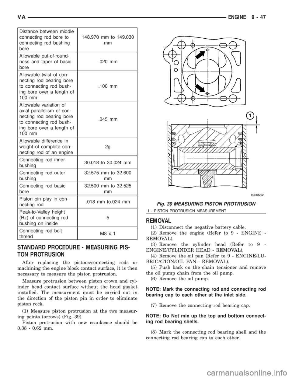
(1) Measure piston protrusion at the two measur-
ing points (arrows) (Fig. 39).
Piston protrusion with new crankcase should be
0.38 - 0.62 mm.
REMOVAL
(1) Disconnect the negative battery cable.
(2) Remove the engine (Refer to 9 - ENGINE -
REMOVAL).
(3) Remove the cylinder head (Refer to 9 -
ENGINE/CYLINDER HEAD - REMOVAL).
(4) Remove the oil pan (Refer to 9 - ENGINE/LU-
BRICATION/OIL PAN - REMOVAL).
(5) Push back on the chain tensioner and remove
the oil pump chain from the oil pump.
(6) Remove the oil pump.
NOTE: Mark the connecting rod and connecting rod
bearing cap to each other at the inlet side.
(7) Remove the connecting rod bearing cap.
NOTE: Do Not mix up the top and bottom connect-
ing rod bearing shells.
(8) Mark the connecting rod bearing shell and the
connecting rod bearing cap to each other.
Fig. 39 MEASURING PISTON PROTRUSION
1 - PISTON PROTRUSION MEASUREMENT
VAENGINE 9 - 47
Page 1624 of 2305
(10) Mark the connecting rod bearing shell and
connecting rod to each other.
CAUTION: Care must be taken not to damage the
piston.
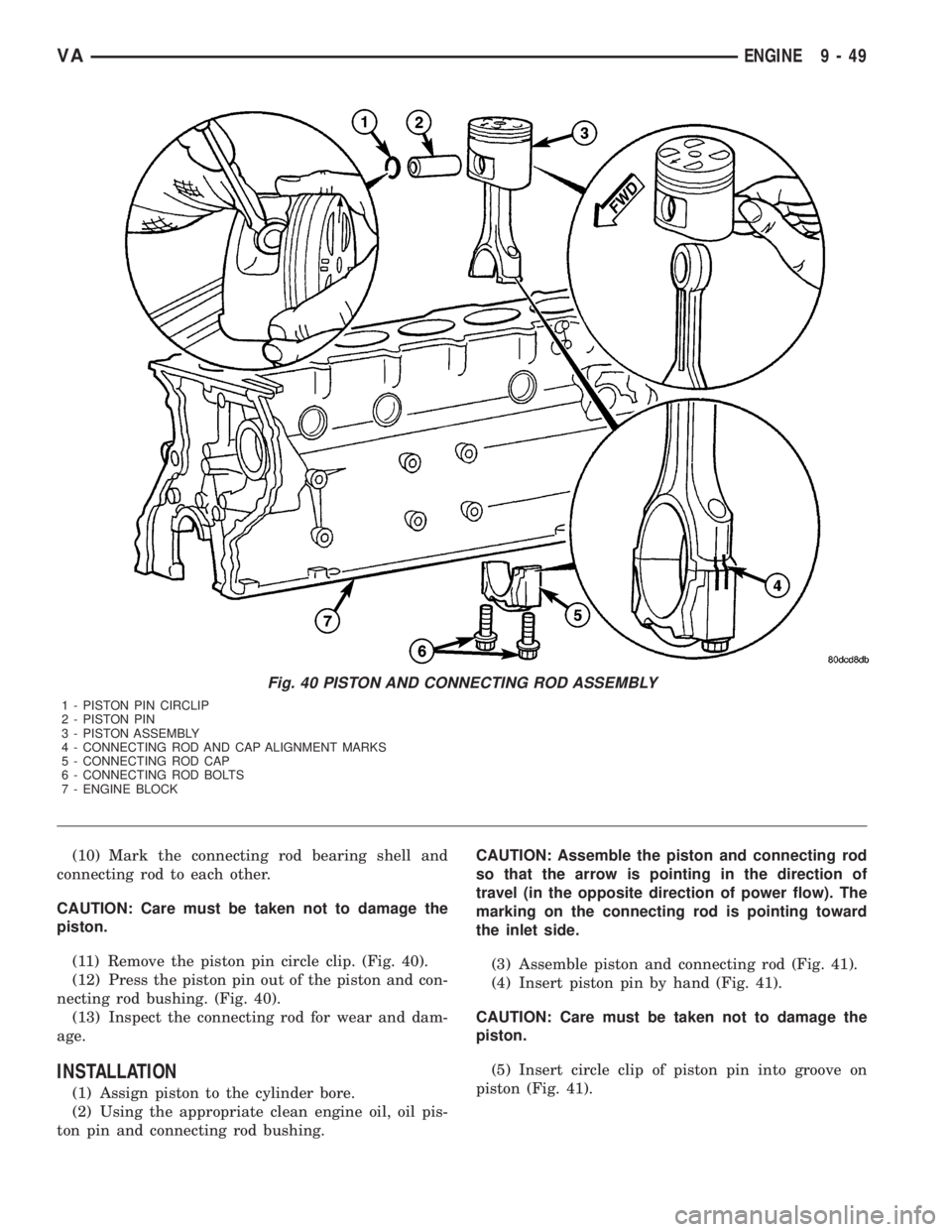
(11) Remove the piston pin circle clip. (Fig. 40).
(12) Press the piston pin out of the piston and con-
necting rod bushing. (Fig. 40).
(13) Inspect the connecting rod for wear and dam-
age.
INSTALLATION
(1) Assign piston to the cylinder bore.
(2) Using the appropriate clean engine oil, oil pis-
ton pin and connecting rod bushing.CAUTION: Assemble the piston and connecting rod
so that the arrow is pointing in the direction of
travel (in the opposite direction of power flow). The
marking on the connecting rod is pointing toward
the inlet side.
(3) Assemble piston and connecting rod (Fig. 41).
(4) Insert piston pin by hand (Fig. 41).
CAUTION: Care must be taken not to damage the
piston.
(5) Insert circle clip of piston pin into groove on
piston (Fig. 41).
Fig. 40 PISTON AND CONNECTING ROD ASSEMBLY
1 - PISTON PIN CIRCLIP
2 - PISTON PIN
3 - PISTON ASSEMBLY
4 - CONNECTING ROD AND CAP ALIGNMENT MARKS
5 - CONNECTING ROD CAP
6 - CONNECTING ROD BOLTS
7 - ENGINE BLOCK
VAENGINE 9 - 49
Page 1626 of 2305
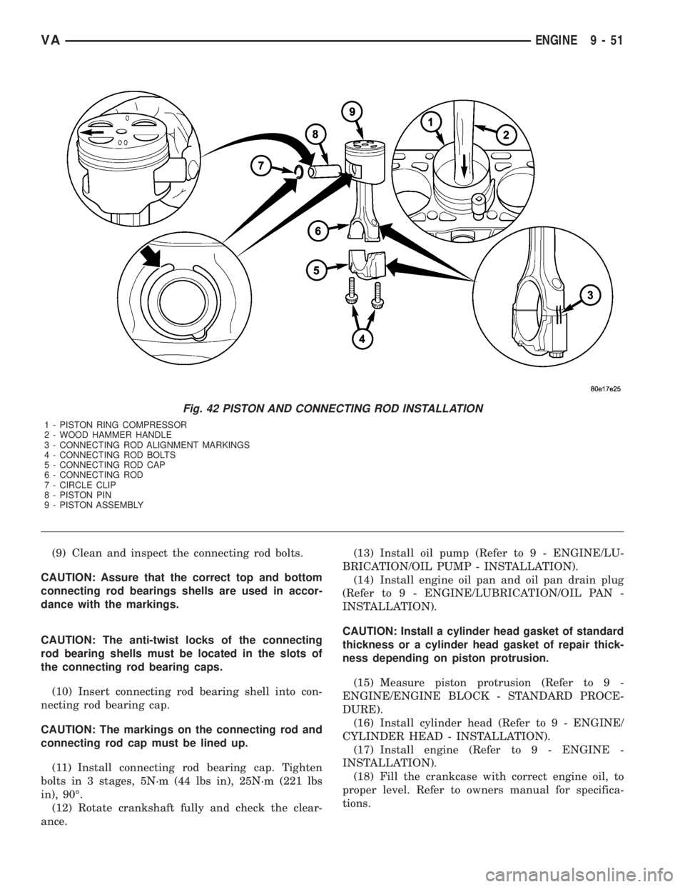
(9) Clean and inspect the connecting rod bolts.
CAUTION: Assure that the correct top and bottom
connecting rod bearings shells are used in accor-
dance with the markings.
CAUTION: The anti-twist locks of the connecting
rod bearing shells must be located in the slots of
the connecting rod bearing caps.
(10) Insert connecting rod bearing shell into con-
necting rod bearing cap.
CAUTION: The markings on the connecting rod and
connecting rod cap must be lined up.
(11) Install connecting rod bearing cap. Tighten
bolts in 3 stages, 5N´m (44 lbs in), 25N´m (221 lbs
in), 90É.
(12) Rotate crankshaft fully and check the clear-
ance.(13) Install oil pump (Refer to 9 - ENGINE/LU-
BRICATION/OIL PUMP - INSTALLATION).
(14) Install engine oil pan and oil pan drain plug
(Refer to 9 - ENGINE/LUBRICATION/OIL PAN -
INSTALLATION).
CAUTION: Install a cylinder head gasket of standard
thickness or a cylinder head gasket of repair thick-
ness depending on piston protrusion.
(15) Measure piston protrusion (Refer to 9 -
ENGINE/ENGINE BLOCK - STANDARD PROCE-
DURE).
(16) Install cylinder head (Refer to 9 - ENGINE/
CYLINDER HEAD - INSTALLATION).
(17) Install engine (Refer to 9 - ENGINE -
INSTALLATION).
(18) Fill the crankcase with correct engine oil, to
proper level. Refer to owners manual for specifica-
tions.
Fig. 42 PISTON AND CONNECTING ROD INSTALLATION
1 - PISTON RING COMPRESSOR
2 - WOOD HAMMER HANDLE
3 - CONNECTING ROD ALIGNMENT MARKINGS
4 - CONNECTING ROD BOLTS
5 - CONNECTING ROD CAP
6 - CONNECTING ROD
7 - CIRCLE CLIP
8 - PISTON PIN
9 - PISTON ASSEMBLY
VAENGINE 9 - 51
Page 1628 of 2305
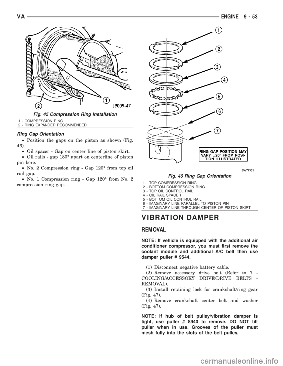
Ring Gap Orientation
²Position the gaps on the piston as shown (Fig.
46).
²Oil spacer - Gap on center line of piston skirt.
²Oil rails - gap 180É apart on centerline of piston
pin bore.
²No. 2 Compression ring - Gap 120É from top oil
rail gap.
²No. 1 Compression ring - Gap 120É from No. 2
compression ring gap.
VIBRATION DAMPER
REMOVAL
NOTE: If vehicle is equipped with the additional air
conditioner compressor, you must first remove the
coolant module and additional A/C belt then use
damper puller # 9544.
(1) Disconnect negative battery cable.
(2) Remove accessory drive belt (Refer to 7 -
COOLING/ACCESSORY DRIVE/DRIVE BELTS -
REMOVAL).
(3) Install retaining lock for crankshaft/ring gear
(Fig. 47).
(4) Remove crankshaft center bolt and washer
(Fig. 47).
NOTE: If hub of belt pulley/vibration damper is
tight, use puller # 8940 to remove. DO NOT tilt
puller when in use. Grooves of the puller must
mesh fully into the slots of the belt pulley.
Fig. 45 Compression Ring Installation
1 - COMPRESSION RING
2 - RING EXPANDER RECOMMENDED
Fig. 46 Ring Gap Orientation
1 - TOP COMPRESSION RING
2 - BOTTOM COMPRESSION RING
3 - TOP OIL CONTROL RAIL
4 - OIL RAIL SPACER
5 - BOTTOM OIL CONTROL RAIL
6 - IMAGINARY LINE PARALLEL TO PISTON PIN
7 - IMAGINARY LINE THROUGH CENTER OF PISTON SKIRT
VAENGINE 9 - 53
Page 1629 of 2305
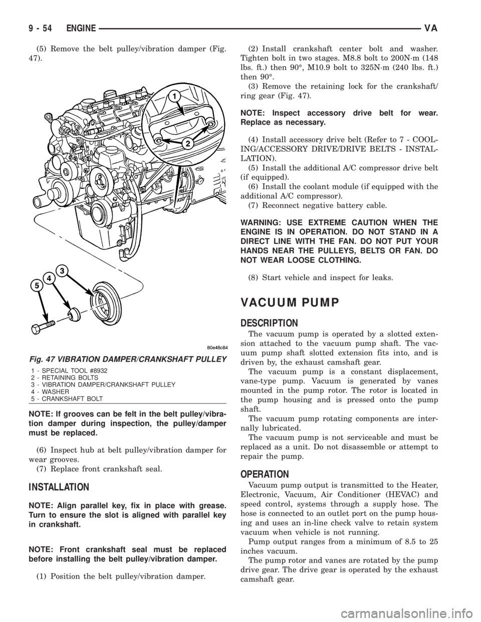
(5) Remove the belt pulley/vibration damper (Fig.
47).
NOTE: If grooves can be felt in the belt pulley/vibra-
tion damper during inspection, the pulley/damper
must be replaced.
(6) Inspect hub at belt pulley/vibration damper for
wear grooves.
(7) Replace front crankshaft seal.
INSTALLATION
NOTE: Align parallel key, fix in place with grease.
Turn to ensure the slot is aligned with parallel key
in crankshaft.
NOTE: Front crankshaft seal must be replaced
before installing the belt pulley/vibration damper.
(1) Position the belt pulley/vibration damper.(2) Install crankshaft center bolt and washer.
Tighten bolt in two stages. M8.8 bolt to 200N´m (148
lbs. ft.) then 90É, M10.9 bolt to 325N´m (240 lbs. ft.)
then 90É.
(3) Remove the retaining lock for the crankshaft/
ring gear (Fig. 47).
NOTE: Inspect accessory drive belt for wear.
Replace as necessary.
(4) Install accessory drive belt (Refer to 7 - COOL-
ING/ACCESSORY DRIVE/DRIVE BELTS - INSTAL-
LATION).
(5) Install the additional A/C compressor drive belt
(if equipped).
(6) Install the coolant module (if equipped with the
additional A/C compressor).
(7) Reconnect negative battery cable.
WARNING: USE EXTREME CAUTION WHEN THE
ENGINE IS IN OPERATION. DO NOT STAND IN A
DIRECT LINE WITH THE FAN. DO NOT PUT YOUR
HANDS NEAR THE PULLEYS, BELTS OR FAN. DO
NOT WEAR LOOSE CLOTHING.
(8) Start vehicle and inspect for leaks.
VACUUM PUMP
DESCRIPTION
The vacuum pump is operated by a slotted exten-
sion attached to the vacuum pump shaft. The vac-
uum pump shaft slotted extension fits into, and is
driven by, the exhaust camshaft gear.
The vacuum pump is a constant displacement,
vane-type pump. Vacuum is generated by vanes
mounted in the pump rotor. The rotor is located in
the pump housing and is pressed onto the pump
shaft.
The vacuum pump rotating components are inter-
nally lubricated.
The vacuum pump is not serviceable and must be
replaced as a unit. Do not disassemble or attempt to
repair the pump.
OPERATION
Vacuum pump output is transmitted to the Heater,
Electronic, Vacuum, Air Conditioner (HEVAC) and
speed control, systems through a supply hose. The
hose is connected to an outlet port on the pump hous-
ing and uses an in-line check valve to retain system
vacuum when vehicle is not running.
Pump output ranges from a minimum of 8.5 to 25
inches vacuum.
The pump rotor and vanes are rotated by the pump
drive gear. The drive gear is operated by the exhaust
camshaft gear.
Fig. 47 VIBRATION DAMPER/CRANKSHAFT PULLEY
1 - SPECIAL TOOL #8932
2 - RETAINING BOLTS
3 - VIBRATION DAMPER/CRANKSHAFT PULLEY
4 - WASHER
5 - CRANKSHAFT BOLT
9 - 54 ENGINEVA
Page 1632 of 2305
INSTALLATION
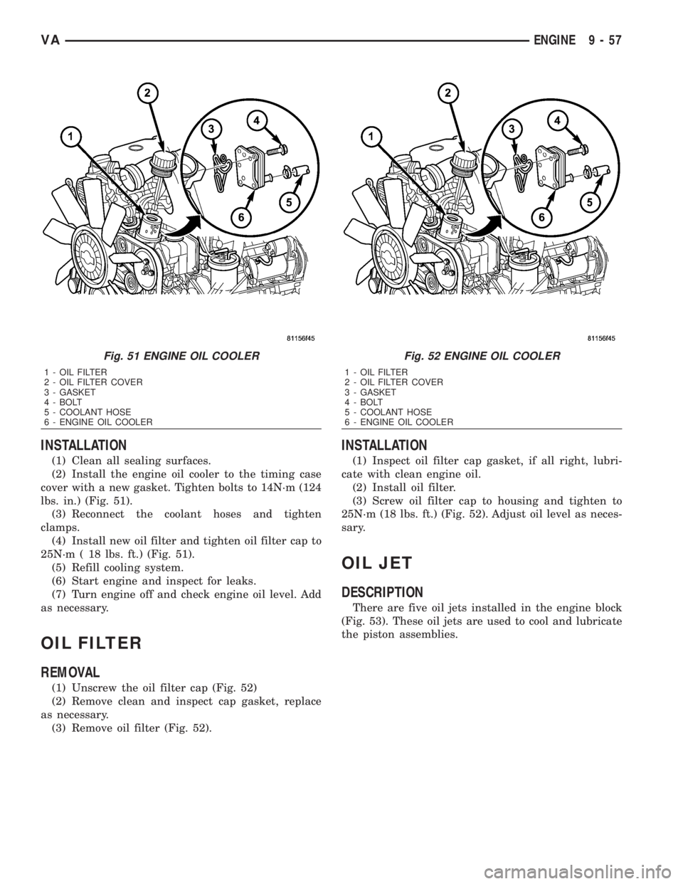
(1) Clean all sealing surfaces.
(2) Install the engine oil cooler to the timing case
cover with a new gasket. Tighten bolts to 14N´m (124
lbs. in.) (Fig. 51).
(3) Reconnect the coolant hoses and tighten
clamps.
(4) Install new oil filter and tighten oil filter cap to
25N´m ( 18 lbs. ft.) (Fig. 51).
(5) Refill cooling system.
(6) Start engine and inspect for leaks.
(7) Turn engine off and check engine oil level. Add
as necessary.
OIL FILTER
REMOVAL
(1) Unscrew the oil filter cap (Fig. 52)
(2) Remove clean and inspect cap gasket, replace
as necessary.
(3) Remove oil filter (Fig. 52).
INSTALLATION
(1) Inspect oil filter cap gasket, if all right, lubri-
cate with clean engine oil.
(2) Install oil filter.
(3) Screw oil filter cap to housing and tighten to
25N´m (18 lbs. ft.) (Fig. 52). Adjust oil level as neces-
sary.
OIL JET
DESCRIPTION
There are five oil jets installed in the engine block
(Fig. 53). These oil jets are used to cool and lubricate
the piston assemblies.
Fig. 51 ENGINE OIL COOLER
1 - OIL FILTER
2 - OIL FILTER COVER
3 - GASKET
4 - BOLT
5 - COOLANT HOSE
6 - ENGINE OIL COOLER
Fig. 52 ENGINE OIL COOLER
1 - OIL FILTER
2 - OIL FILTER COVER
3 - GASKET
4 - BOLT
5 - COOLANT HOSE
6 - ENGINE OIL COOLER
VAENGINE 9 - 57