2006 MERCEDES-BENZ SPRINTER lock
[x] Cancel search: lockPage 2278 of 2305
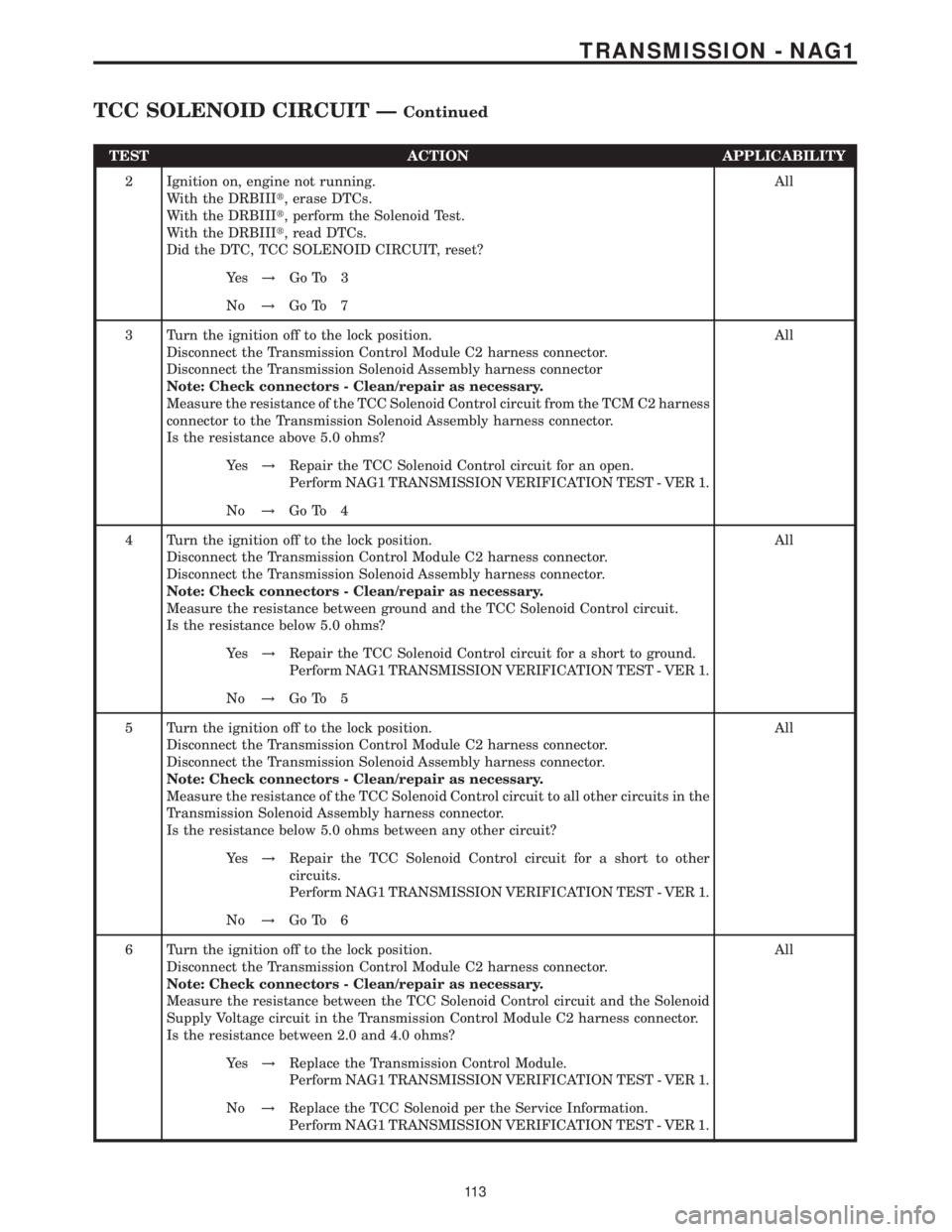
TEST ACTION APPLICABILITY
2 Ignition on, engine not running.
With the DRBIIIt, erase DTCs.
With the DRBIIIt, perform the Solenoid Test.
With the DRBIIIt, read DTCs.
Did the DTC, TCC SOLENOID CIRCUIT, reset?All
Ye s!Go To 3
No!Go To 7
3 Turn the ignition off to the lock position.
Disconnect the Transmission Control Module C2 harness connector.
Disconnect the Transmission Solenoid Assembly harness connector
Note: Check connectors - Clean/repair as necessary.
Measure the resistance of the TCC Solenoid Control circuit from the TCM C2 harness
connector to the Transmission Solenoid Assembly harness connector.
Is the resistance above 5.0 ohms?All
Ye s!Repair the TCC Solenoid Control circuit for an open.
Perform NAG1 TRANSMISSION VERIFICATION TEST - VER 1.
No!Go To 4
4 Turn the ignition off to the lock position.
Disconnect the Transmission Control Module C2 harness connector.
Disconnect the Transmission Solenoid Assembly harness connector.
Note: Check connectors - Clean/repair as necessary.
Measure the resistance between ground and the TCC Solenoid Control circuit.
Is the resistance below 5.0 ohms?All
Ye s!Repair the TCC Solenoid Control circuit for a short to ground.
Perform NAG1 TRANSMISSION VERIFICATION TEST - VER 1.
No!Go To 5
5 Turn the ignition off to the lock position.
Disconnect the Transmission Control Module C2 harness connector.
Disconnect the Transmission Solenoid Assembly harness connector.
Note: Check connectors - Clean/repair as necessary.
Measure the resistance of the TCC Solenoid Control circuit to all other circuits in the
Transmission Solenoid Assembly harness connector.
Is the resistance below 5.0 ohms between any other circuit?All
Ye s!Repair the TCC Solenoid Control circuit for a short to other
circuits.
Perform NAG1 TRANSMISSION VERIFICATION TEST - VER 1.
No!Go To 6
6 Turn the ignition off to the lock position.
Disconnect the Transmission Control Module C2 harness connector.
Note: Check connectors - Clean/repair as necessary.
Measure the resistance between the TCC Solenoid Control circuit and the Solenoid
Supply Voltage circuit in the Transmission Control Module C2 harness connector.
Is the resistance between 2.0 and 4.0 ohms?All
Ye s!Replace the Transmission Control Module.
Perform NAG1 TRANSMISSION VERIFICATION TEST - VER 1.
No!Replace the TCC Solenoid per the Service Information.
Perform NAG1 TRANSMISSION VERIFICATION TEST - VER 1.
11 3
TRANSMISSION - NAG1
TCC SOLENOID CIRCUIT ÐContinued
Page 2281 of 2305
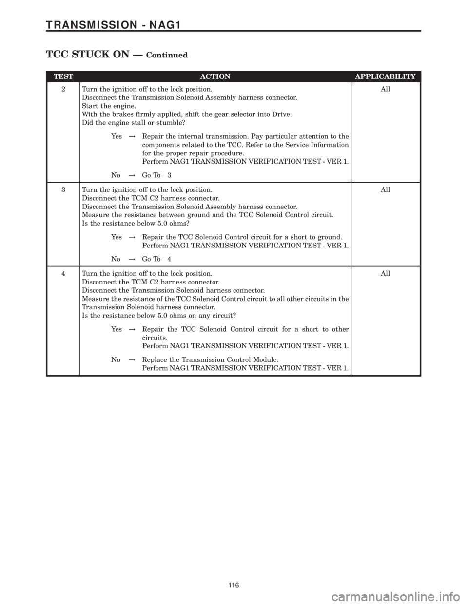
TEST ACTION APPLICABILITY
2 Turn the ignition off to the lock position.
Disconnect the Transmission Solenoid Assembly harness connector.
Start the engine.
With the brakes firmly applied, shift the gear selector into Drive.
Did the engine stall or stumble?All
Ye s!Repair the internal transmission. Pay particular attention to the
components related to the TCC. Refer to the Service Information
for the proper repair procedure.
Perform NAG1 TRANSMISSION VERIFICATION TEST - VER 1.
No!Go To 3
3 Turn the ignition off to the lock position.
Disconnect the TCM C2 harness connector.
Disconnect the Transmission Solenoid Assembly harness connector.
Measure the resistance between ground and the TCC Solenoid Control circuit.
Is the resistance below 5.0 ohms?All
Ye s!Repair the TCC Solenoid Control circuit for a short to ground.
Perform NAG1 TRANSMISSION VERIFICATION TEST - VER 1.
No!Go To 4
4 Turn the ignition off to the lock position.
Disconnect the TCM C2 harness connector.
Disconnect the Transmission Solenoid harness connector.
Measure the resistance of the TCC Solenoid Control circuit to all other circuits in the
Transmission Solenoid harness connector.
Is the resistance below 5.0 ohms on any circuit?All
Ye s!Repair the TCC Solenoid Control circuit for a short to other
circuits.
Perform NAG1 TRANSMISSION VERIFICATION TEST - VER 1.
No!Replace the Transmission Control Module.
Perform NAG1 TRANSMISSION VERIFICATION TEST - VER 1.
11 6
TRANSMISSION - NAG1
TCC STUCK ON ÐContinued
Page 2283 of 2305
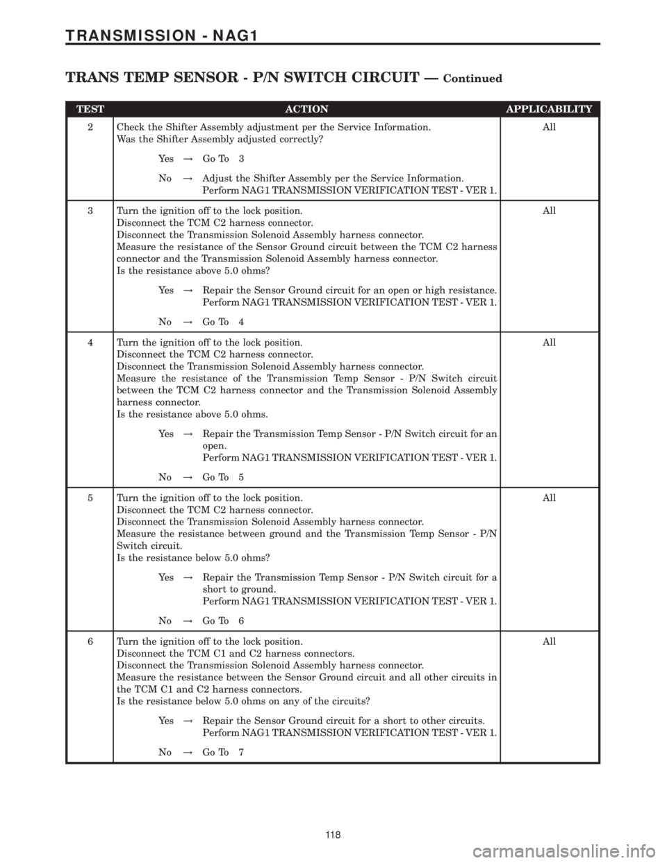
TEST ACTION APPLICABILITY
2 Check the Shifter Assembly adjustment per the Service Information.
Was the Shifter Assembly adjusted correctly?All
Ye s!Go To 3
No!Adjust the Shifter Assembly per the Service Information.
Perform NAG1 TRANSMISSION VERIFICATION TEST - VER 1.
3 Turn the ignition off to the lock position.
Disconnect the TCM C2 harness connector.
Disconnect the Transmission Solenoid Assembly harness connector.
Measure the resistance of the Sensor Ground circuit between the TCM C2 harness
connector and the Transmission Solenoid Assembly harness connector.
Is the resistance above 5.0 ohms?All
Ye s!Repair the Sensor Ground circuit for an open or high resistance.
Perform NAG1 TRANSMISSION VERIFICATION TEST - VER 1.
No!Go To 4
4 Turn the ignition off to the lock position.
Disconnect the TCM C2 harness connector.
Disconnect the Transmission Solenoid Assembly harness connector.
Measure the resistance of the Transmission Temp Sensor - P/N Switch circuit
between the TCM C2 harness connector and the Transmission Solenoid Assembly
harness connector.
Is the resistance above 5.0 ohms.All
Ye s!Repair the Transmission Temp Sensor - P/N Switch circuit for an
open.
Perform NAG1 TRANSMISSION VERIFICATION TEST - VER 1.
No!Go To 5
5 Turn the ignition off to the lock position.
Disconnect the TCM C2 harness connector.
Disconnect the Transmission Solenoid Assembly harness connector.
Measure the resistance between ground and the Transmission Temp Sensor - P/N
Switch circuit.
Is the resistance below 5.0 ohms?All
Ye s!Repair the Transmission Temp Sensor - P/N Switch circuit for a
short to ground.
Perform NAG1 TRANSMISSION VERIFICATION TEST - VER 1.
No!Go To 6
6 Turn the ignition off to the lock position.
Disconnect the TCM C1 and C2 harness connectors.
Disconnect the Transmission Solenoid Assembly harness connector.
Measure the resistance between the Sensor Ground circuit and all other circuits in
the TCM C1 and C2 harness connectors.
Is the resistance below 5.0 ohms on any of the circuits?All
Ye s!Repair the Sensor Ground circuit for a short to other circuits.
Perform NAG1 TRANSMISSION VERIFICATION TEST - VER 1.
No!Go To 7
11 8
TRANSMISSION - NAG1
TRANS TEMP SENSOR - P/N SWITCH CIRCUIT ÐContinued
Page 2284 of 2305
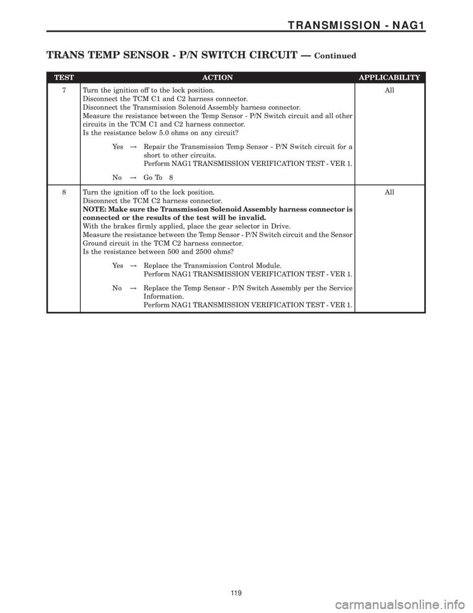
TEST ACTION APPLICABILITY
7 Turn the ignition off to the lock position.
Disconnect the TCM C1 and C2 harness connector.
Disconnect the Transmission Solenoid Assembly harness connector.
Measure the resistance between the Temp Sensor - P/N Switch circuit and all other
circuits in the TCM C1 and C2 harness connector.
Is the resistance below 5.0 ohms on any circuit?All
Ye s!Repair the Transmission Temp Sensor - P/N Switch circuit for a
short to other circuits.
Perform NAG1 TRANSMISSION VERIFICATION TEST - VER 1.
No!Go To 8
8 Turn the ignition off to the lock position.
Disconnect the TCM C2 harness connector.
NOTE: Make sure the Transmission Solenoid Assembly harness connector is
connected or the results of the test will be invalid.
With the brakes firmly applied, place the gear selector in Drive.
Measure the resistance between the Temp Sensor - P/N Switch circuit and the Sensor
Ground circuit in the TCM C2 harness connector.
Is the resistance between 500 and 2500 ohms?All
Ye s!Replace the Transmission Control Module.
Perform NAG1 TRANSMISSION VERIFICATION TEST - VER 1.
No!Replace the Temp Sensor - P/N Switch Assembly per the Service
Information.
Perform NAG1 TRANSMISSION VERIFICATION TEST - VER 1.
11 9
TRANSMISSION - NAG1
TRANS TEMP SENSOR - P/N SWITCH CIRCUIT ÐContinued
Page 2288 of 2305
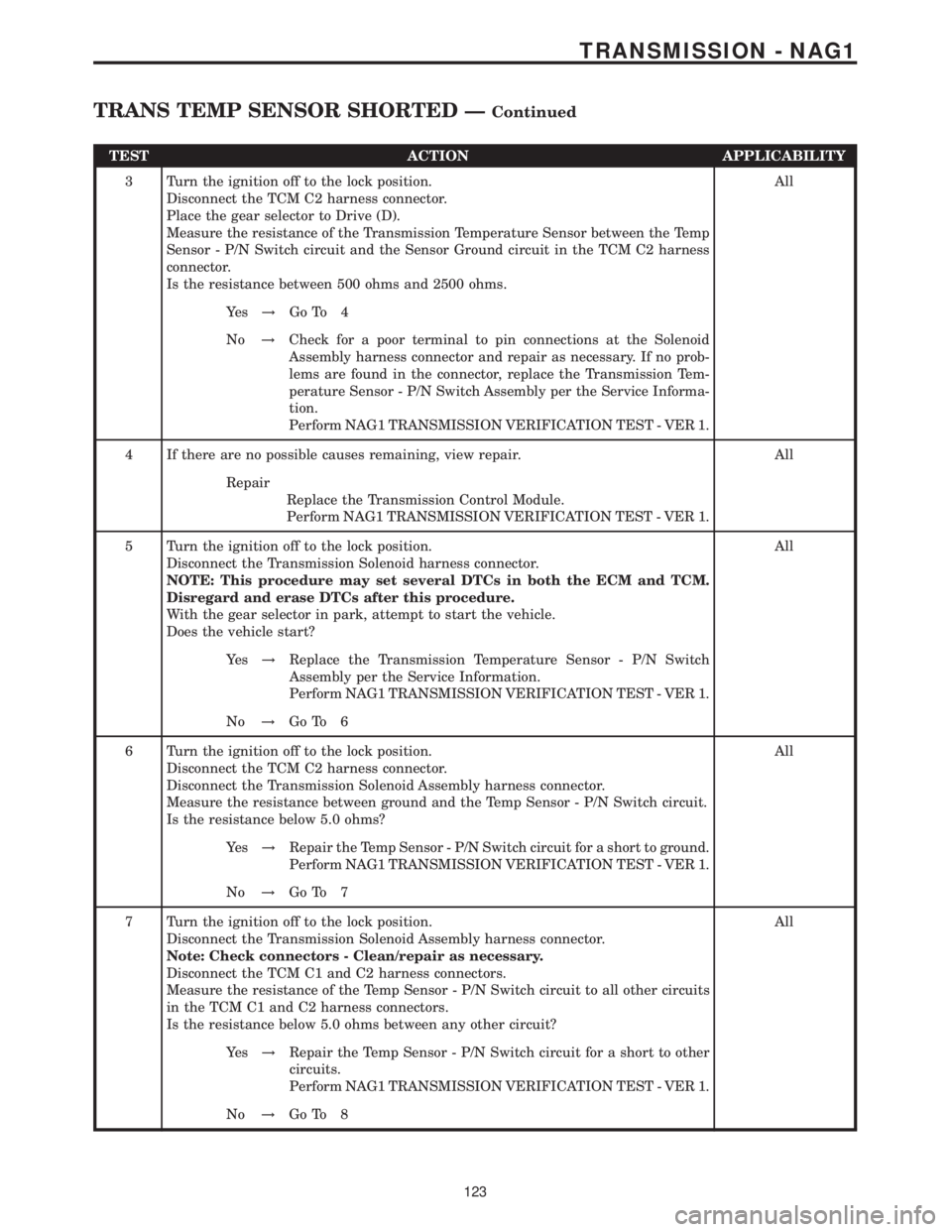
TEST ACTION APPLICABILITY
3 Turn the ignition off to the lock position.
Disconnect the TCM C2 harness connector.
Place the gear selector to Drive (D).
Measure the resistance of the Transmission Temperature Sensor between the Temp
Sensor - P/N Switch circuit and the Sensor Ground circuit in the TCM C2 harness
connector.
Is the resistance between 500 ohms and 2500 ohms.All
Ye s!Go To 4
No!Check for a poor terminal to pin connections at the Solenoid
Assembly harness connector and repair as necessary. If no prob-
lems are found in the connector, replace the Transmission Tem-
perature Sensor - P/N Switch Assembly per the Service Informa-
tion.
Perform NAG1 TRANSMISSION VERIFICATION TEST - VER 1.
4 If there are no possible causes remaining, view repair. All
Repair
Replace the Transmission Control Module.
Perform NAG1 TRANSMISSION VERIFICATION TEST - VER 1.
5 Turn the ignition off to the lock position.
Disconnect the Transmission Solenoid harness connector.
NOTE: This procedure may set several DTCs in both the ECM and TCM.
Disregard and erase DTCs after this procedure.
With the gear selector in park, attempt to start the vehicle.
Does the vehicle start?All
Ye s!Replace the Transmission Temperature Sensor - P/N Switch
Assembly per the Service Information.
Perform NAG1 TRANSMISSION VERIFICATION TEST - VER 1.
No!Go To 6
6 Turn the ignition off to the lock position.
Disconnect the TCM C2 harness connector.
Disconnect the Transmission Solenoid Assembly harness connector.
Measure the resistance between ground and the Temp Sensor - P/N Switch circuit.
Is the resistance below 5.0 ohms?All
Ye s!Repair the Temp Sensor - P/N Switch circuit for a short to ground.
Perform NAG1 TRANSMISSION VERIFICATION TEST - VER 1.
No!Go To 7
7 Turn the ignition off to the lock position.
Disconnect the Transmission Solenoid Assembly harness connector.
Note: Check connectors - Clean/repair as necessary.
Disconnect the TCM C1 and C2 harness connectors.
Measure the resistance of the Temp Sensor - P/N Switch circuit to all other circuits
in the TCM C1 and C2 harness connectors.
Is the resistance below 5.0 ohms between any other circuit?All
Ye s!Repair the Temp Sensor - P/N Switch circuit for a short to other
circuits.
Perform NAG1 TRANSMISSION VERIFICATION TEST - VER 1.
No!Go To 8
123
TRANSMISSION - NAG1
TRANS TEMP SENSOR SHORTED ÐContinued
Page 2298 of 2305

TRANSMISSION RELAY (RELAY BLOCK)CAV CIRCUIT FUNCTION
30 16BK/DG TRANSMISSION RELAY OUTPUT
85 16BR GROUND
86 16BK/YL FUSED IGNITION SWITCH OUTPUT (RUN-START)
87 16RD FUSED B(+)
87A - -
C
O
N
N
E
C
T
O
R
P
I
N
O
U
T
S
133
CONNECTOR PINOUTS