2006 MERCEDES-BENZ SPRINTER lock
[x] Cancel search: lockPage 1675 of 2305
SPECIFICATIONS - TORQUE
TORQUE SPECIFICATIONS
DESCRIPTION N´m Ft. Lbs. In. Lbs.
Brake line nuts 14 10 Ð
Brake pads wear
indicator caliper
bolt10 7 89
Engine cradle bolts 125 92 Ð
Engine mount bolt
to engine bracket83 61 Ð
Engine mount nuts
to engine cradle45 33 Ð
Power steering line
nuts37 27 Ð
Steering gear
mounting bolts -
1st stage25 18 Ð
Steering Gear
mounting bolts -
2nd stage45 33 Ð
Steering Gear
mounting bolts -
3rd stage90ÉÐÐ
Steering gear u-
joint bolt24 18 Ð
Sway bar bushing
bolts30 22 Ð
Trailer hitch angle
bracket bolts/nuts50*
See
Warning37*
See
WarningÐ
Trailer hitch frame
bolts11 0 8 1 Ð
Transmission cross-
member nuts45 33 Ð
Transmission
mount bolts/nuts45 33 Ð
WARNING: Microencapsulated bolts and self-lock-
ing nuts may only be used once. If you use
microencapsulated bolt or self-locking nuts more
than once, the self-locking function is rendered
useless. The trailer hitch may become detached
from the vehicle, possibly resulting in a serious risk
of injury and/or damage to property, including dam-
age to the vehicle.
ENGINE CRADLE CROSSMEM-
BER
REMOVAL
(1) Install engine support tool 8534 or equivalent.
(2) Raise and support the vehicle. (Refer to
LUBRICATION & MAINTENANCE/HOISTING -
STANDARD PROCEDURE)
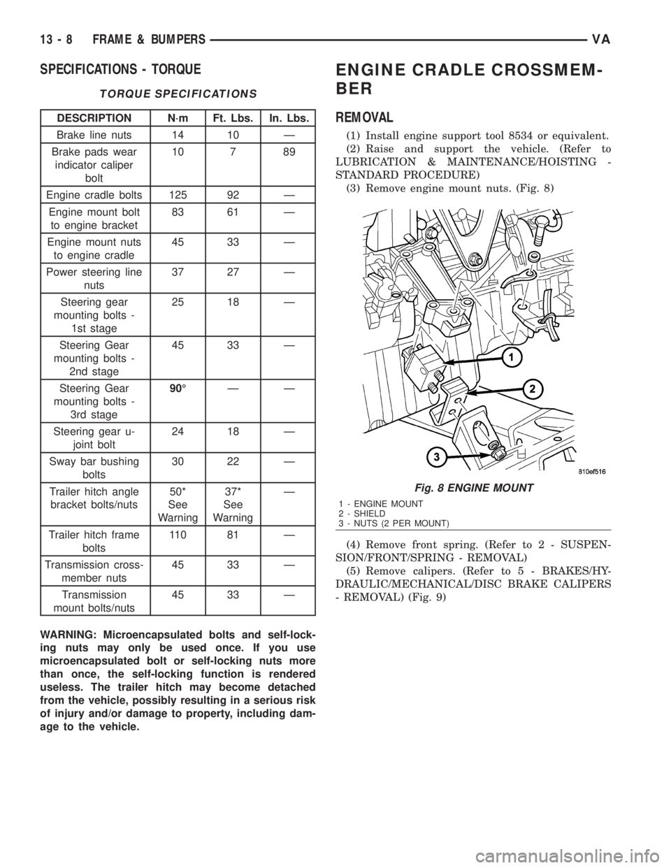
(3) Remove engine mount nuts. (Fig. 8)
(4) Remove front spring. (Refer to 2 - SUSPEN-
SION/FRONT/SPRING - REMOVAL)
(5) Remove calipers. (Refer to 5 - BRAKES/HY-
DRAULIC/MECHANICAL/DISC BRAKE CALIPERS
- REMOVAL) (Fig. 9)
Fig. 8 ENGINE MOUNT
1 - ENGINE MOUNT
2 - SHIELD
3 - NUTS (2 PER MOUNT)
13 - 8 FRAME & BUMPERSVA
Page 1679 of 2305
WARNING: Microencapsulated bolts and self-lock-
ing nuts may only be used once. If you use
microencapsulated bolt or self-locking nuts more
than once, the self-locking function is rendered
useless. The trailer hitch may become detached
from the vehicle, possibly resulting in a serious risk
of injury and/or damage to property, including dam-
age to the vehicle.
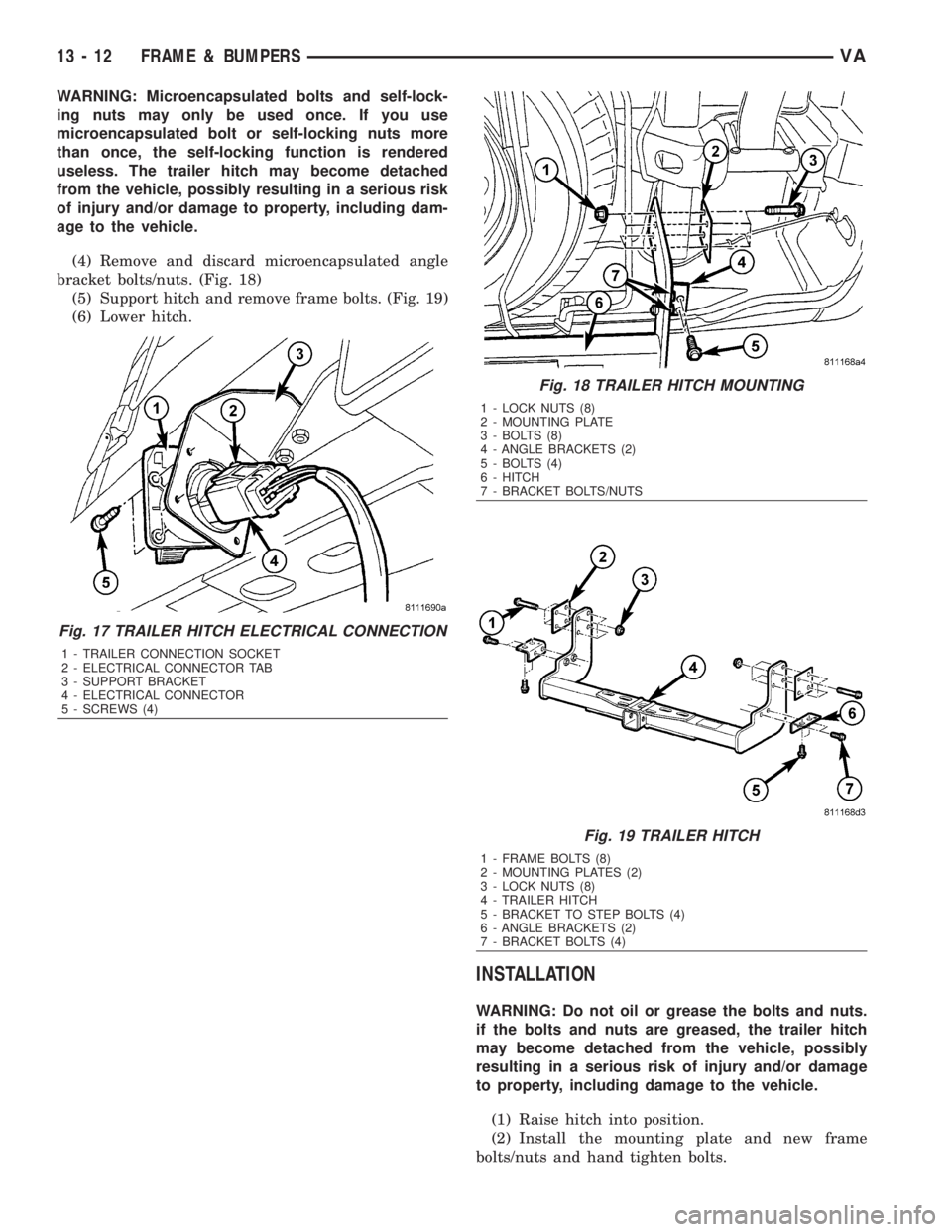
(4) Remove and discard microencapsulated angle
bracket bolts/nuts. (Fig. 18)
(5) Support hitch and remove frame bolts. (Fig. 19)
(6) Lower hitch.
INSTALLATION
WARNING: Do not oil or grease the bolts and nuts.
if the bolts and nuts are greased, the trailer hitch
may become detached from the vehicle, possibly
resulting in a serious risk of injury and/or damage
to property, including damage to the vehicle.
(1) Raise hitch into position.
(2) Install the mounting plate and new frame
bolts/nuts and hand tighten bolts.
Fig. 17 TRAILER HITCH ELECTRICAL CONNECTION
1 - TRAILER CONNECTION SOCKET
2 - ELECTRICAL CONNECTOR TAB
3 - SUPPORT BRACKET
4 - ELECTRICAL CONNECTOR
5 - SCREWS (4)
Fig. 18 TRAILER HITCH MOUNTING
1 - LOCK NUTS (8)
2 - MOUNTING PLATE
3 - BOLTS (8)
4 - ANGLE BRACKETS (2)
5 - BOLTS (4)
6 - HITCH
7 - BRACKET BOLTS/NUTS
Fig. 19 TRAILER HITCH
1 - FRAME BOLTS (8)
2 - MOUNTING PLATES (2)
3 - LOCK NUTS (8)
4 - TRAILER HITCH
5 - BRACKET TO STEP BOLTS (4)
6 - ANGLE BRACKETS (2)
7 - BRACKET BOLTS (4)
13 - 12 FRAME & BUMPERSVA
Page 1680 of 2305
WARNING: Microencapsulated bolts and self-lock-
ing nuts may only be used once. If you use
microencapsulated bolt or self-locking nuts more
than once, the self-locking function is rendered
useless. The trailer hitch may become detached
from the vehicle, possibly resulting in a serious risk
of injury and/or damage to property, including dam-
age to the vehicle.
(3) Install the angle bracket microencapsulated
bolts/nuts and hand tighten.
(4) Align trailer hitch.
(5) Tighten the frame mounting bolts to 110 N´m
(81 ft. lbs.).
(6) Tighten microencapsulated angle bracket bolts
to 50 N´m (37 ft. lbs.)
(7) Connect trailer socket electrical connector.
VAFRAME & BUMPERS 13 - 13
Page 1684 of 2305
(7) Connect a scan tool, select from Main Menu,
System Select, Engine, System Tests, Fuel Quantity
Test, Engine Cranking Test and follow the screen.
(8) After ten seconds, a maximum of 2.5 ml
(between2&3graduation lines) may be reached in
the inner vials. If the level has exceeded the 2.5 ml,
replace that affected cylinder's injector, clear the
memory using the scan tool, empty the test vials, and
retest.
RUNNING TEST
NOTE: If an injector is found to be out of specifica-
tion, repeat this test procedure after the injector
replacement. Hydraulic flow will take the path of
least resistance and multiple failures may be identi-
fied. Engine temperature must be above 80É C
(176ÉF) to perform the running test.
Perform this test with the engine at operating tem-
perature. This test will assist in determining a defec-
tive or internally leaking injector(s) is present by
measuring the amount of fuel return.
(1) Turn the ignition off.
(2) Remove the engine cover (Refer to 9 - ENGINE
- REMOVAL).
(3) Disconnect the fuel return hoses at the top of
the injectors.
(4) Pinch off the fuel return line at the banjo bolt
fitting of the fuel rail.
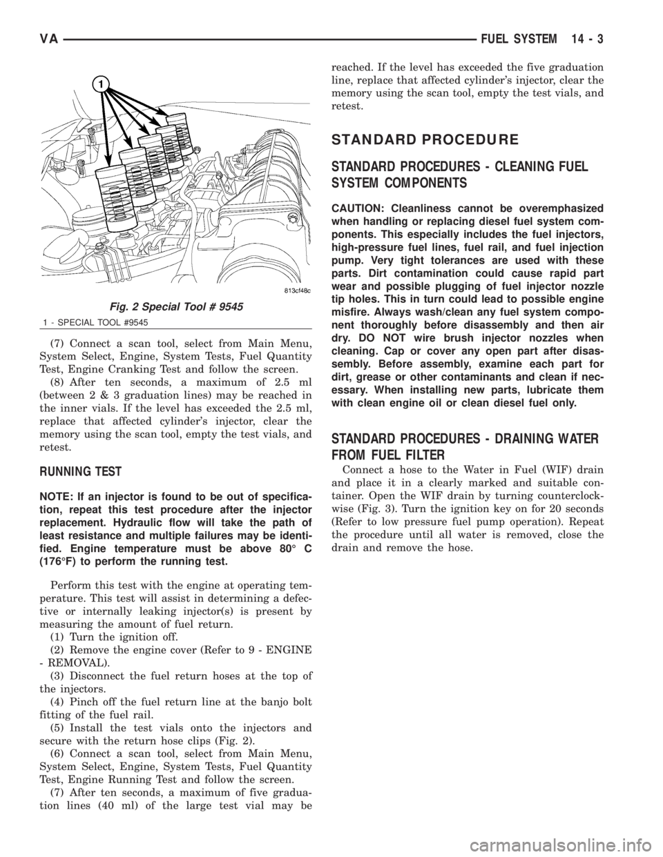
(5) Install the test vials onto the injectors and
secure with the return hose clips (Fig. 2).
(6) Connect a scan tool, select from Main Menu,
System Select, Engine, System Tests, Fuel Quantity
Test, Engine Running Test and follow the screen.
(7) After ten seconds, a maximum of five gradua-
tion lines (40 ml) of the large test vial may bereached. If the level has exceeded the five graduation
line, replace that affected cylinder's injector, clear the
memory using the scan tool, empty the test vials, and
retest.
STANDARD PROCEDURE
STANDARD PROCEDURES - CLEANING FUEL
SYSTEM COMPONENTS
CAUTION: Cleanliness cannot be overemphasized
when handling or replacing diesel fuel system com-
ponents. This especially includes the fuel injectors,
high-pressure fuel lines, fuel rail, and fuel injection
pump. Very tight tolerances are used with these
parts. Dirt contamination could cause rapid part
wear and possible plugging of fuel injector nozzle
tip holes. This in turn could lead to possible engine
misfire. Always wash/clean any fuel system compo-
nent thoroughly before disassembly and then air
dry. DO NOT wire brush injector nozzles when
cleaning. Cap or cover any open part after disas-
sembly. Before assembly, examine each part for
dirt, grease or other contaminants and clean if nec-
essary. When installing new parts, lubricate them
with clean engine oil or clean diesel fuel only.
STANDARD PROCEDURES - DRAINING WATER
FROM FUEL FILTER
Connect a hose to the Water in Fuel (WIF) drain
and place it in a clearly marked and suitable con-
tainer. Open the WIF drain by turning counterclock-
wise (Fig. 3). Turn the ignition key on for 20 seconds
(Refer to low pressure fuel pump operation). Repeat
the procedure until all water is removed, close the
drain and remove the hose.
Fig. 2 Special Tool # 9545
1 - SPECIAL TOOL #9545
VAFUEL SYSTEM 14 - 3
Page 1690 of 2305
(4) Fill fuel tank with fresh diesel fuel.
(5) Drain and remove the fuel filter. (Refer to 14 -
FUEL SYSTEM/FUEL DELIVERY/FUEL FILTER /
WATER SEPARATOR - REMOVAL)
(6) Install a new fuel filter. (Refer to 14 - FUEL
SYSTEM/FUEL DELIVERY/FUEL FILTER / WATER
SEPARATOR - INSTALLATION)
(7) Check the engine control module for any diag-
nostic trouble codes (DTCs). Record and clear any
DTCs that are present.
(8) Start and run the engine. Run the engine for
up to 15 minutes to allow time for any DTCs to reset
and shut off the engine.
(9) Check the engine control module for any diag-
nostic trouble codes (DTCs). Record any DTCs that
are present. Refer to the appropriate engine electrical
diagnostics to diagnose any DTCs that were set.
CAUTION: With the high pressure fuel system in
this vehicle, any residual contaminated fuel will be
removed very quickly. Shut off the engine immedi-
ately if signs of engine damage are noted.The engine should then be evaluated to determine
if the contaminated fuel has caused any damage to
the fuel system and/or engine. Indicators that the
fuel system has been damaged include the following:
²Unstable fuel rail pressure. This can manifest
itself as instability of idle speeds, excessive under-
shoot/overshoot at engine start-up, or excessive
undershoot/overshoot when the engine operating con-
ditions change. A typical engine response to a large
rail pressure undershoot would be a decrease in
engine speed or engine stall.
²Excessive noise from the engine. This could indi-
cate poor rail pressure control or the inability of the
injection system to inject the proper amount of fuel.
²Excessive smoke (black or white). This could
indicate the inability of the fuel system to inject the
proper amount of fuel.
NOTE: If any of these conditions are exhibited after
cleaning the fuel system, proceed to the appropri-
ate engine electrical diagnostic information. Repair
the fuel system and/or engine as necessary.
SPECIFICATIONS
TORQUE
DESCRIPTION N´m Ft. Lbs. In. Lbs.
FUEL TANK MOUNTING NUTS 15 - 17 11 - 13 -
FUEL TANK MODULE LOCKRING (LOCK-
NUT)60 44 -
PRESSURE CONTROL VALVE NUT TO
FUEL RAIL (2 STAGES)60, loosen 90É, re-
tighten to 8044, loosen 90É, re-
tighten to 59-
SPECIAL TOOLS
FUEL SYSTEM
SPECIAL TOOL CROSS REFERENCE CHART
MB
TOOL #MILLER
TOOL #DESCRIPTION
N/A 5069-2 FUEL GAUGE
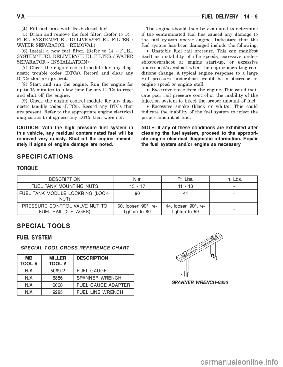
N/A 6856 SPANNER WRENCH
N/A 9068 FUEL GAUGE ADAPTER
N/A 9285 FUEL LINE WRENCH
SPANNER WRENCH-6856
VAFUEL DELIVERY 14 - 9
Page 1691 of 2305
FUEL DRAIN TUBES
DIAGNOSIS AND TESTING - FUEL SUPPLY
RESTRICTIONS
LOW - PRESSURE LINES
Fuel supply line restrictions can cause starting
problems and prevent engine from accelerating. The
starting problems include; low power and/or white
fog like exhaust.
Test all fuel supply lines for restrictions or block-
age. Flush or replace as necessary.
HIGH - PRESSURE LINES
CAUTION: High pressure lines cannot contact each
other or other components. Do not attempt to weld
high-pressure fuel lines or to repair lines that are
damaged. High pressure lines must be replaced at
each disassembly. Use only recommended lines
when replacement of high-pressure fuel line is nec-
essary.
Restricted (kinked or bent) high-pressure lines can
cause starting problems, poor engine performance,engine mis-fire and white smoke from exhaust (Refer
to 14 - FUEL SYSTEM - WARNING).
FUEL FILTER
DESCRIPTION
The fuel filter was designed for improved high alti-
tude operation and for better re-start after the fuel
tank has been completely emptied. The water drain
plug and water in fuel (WIF) sensor are located on
the top of the filter. Water is drained by using the in-
tank electric fuel pump to generate flow (attach a
hose to the drain plug). The filter has a pressure dif-
ferential of 200±300 mbar (2.9 psi.) when new. When
dirty, the pressure differential rises to 800 mbar (11.6
psi.) (Fig. 2).
REMOVAL
WARNING: NO SPARKS, OPEN FLAMES OR SMOK-
ING. RISK OF POISONING FROM INHALING AND
SWALLOWING FUEL. RISK OF INJURY TO EYES
AND SKIN FROM CONTACT WITH FUEL. POUR
FUELS ONLY INTO SUITABLE AND APPROPRI-
ATELY MARKED CONTAINERS. WEAR PROTECTIVE
CLOTHING.
CAUTION: DO NOT bend, twist or cut the fuel hose
clamps. The fuel hose clamps through out the fuel
system are reusable when using special tool #9539.
Orginal clamps must be used when servicing the
fuel system.
(1) Disconnect negative battery cable.
(2) Disconnect the water in fuel (WIF) sensor har-
ness connector (Fig. 2).
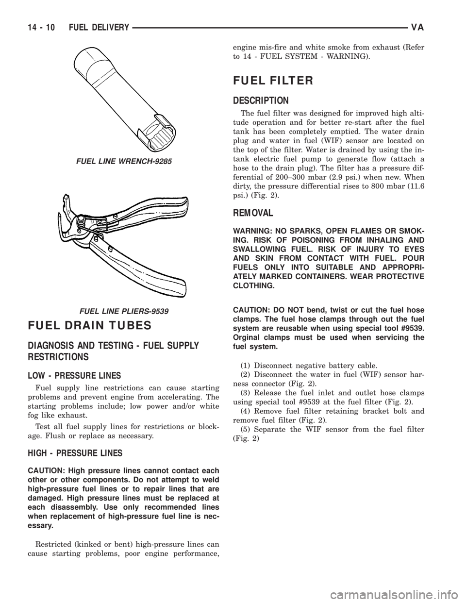
(3) Release the fuel inlet and outlet hose clamps
using special tool #9539 at the fuel filter (Fig. 2).
(4) Remove fuel filter retaining bracket bolt and
remove fuel filter (Fig. 2).
(5) Separate the WIF sensor from the fuel filter
(Fig. 2)
FUEL LINE WRENCH-9285
FUEL LINE PLIERS-9539
14 - 10 FUEL DELIVERYVA
Page 1699 of 2305
CAUTION: DO NOT crimp or bend fuel line. Inspect
sealing cone at line; replace line if compression
exists.
NOTE: Care must be taken not to cross the fuel
return and supply lines during installation.
(2) Attach fuel flow supply and return lines,
recrimping clamps using special tool #9539 (Fig. 9).
CAUTION: NEVER slacken the thread connection.
Use a wrench to counterhold at threaded connec-
tion when slackening and tightening torque in order
to avoid also slackening the threaded connection
the next time.
CAUTION: DO NOT crimp or bend fuel line. Inspect
sealing cone at line; replace line if compression
exists.
(3) Attach high pressure fuel line to pump.
Tighten to 22N´m (194 lbs.in.) (Fig. 9).
(4) Install the viscous fan.
(5) Connect negative battery cable.
(6) Start engine, allow to run, turn engine off and
inspect for leaks (Refer to 14 - FUEL SYSTEM -
WARNING), (Refer to 14 - FUEL SYSTEM - DIAG-
NOSIS AND TESTING).
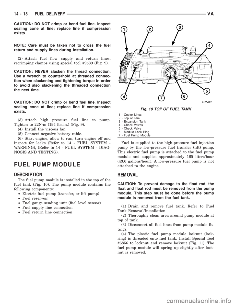
FUEL PUMP MODULE
DESCRIPTION
The fuel pump module is installed in the top of the
fuel tank (Fig. 10). The pump module contains the
following components:
²Electric fuel pump (transfer, or lift pump)
²Fuel reservoir
²Fuel gauge sending unit (fuel level sensor)
²Fuel supply line connection
²Fuel return line connectionFuel is supplied to the high-pressure fuel injection
pump by the low-pressure fuel transfer (lift) pump.
This electric fuel pump is attached to the fuel pump
module and supplies approximately 165 liters/hour
(43.6 gallons/hour). A low-pressure fuel pump is not
attached to the engine.
REMOVAL
CAUTION: To prevent damage to the float rod, the
float and float rod must be removed from the pump
module. This step must be done before the pump
module is removed from the fuel tank.
(1) Drain and remove fuel tank. Refer to Fuel
Tank Removal/Installation.
(2) Thoroughly clean area around pump module at
top of tank.
(3) Disconnect all fuel lines from pump module fit-
tings.
(4) The plastic fuel pump module locknut (lock-
ring) is threaded onto fuel tank. Install Special Tool
#6856 to locknut and remove locknut (Fig. 11). The
fuel pump module will spring up slightly after lock-
nut is removed.
Fig. 10 TOP OF FUEL TANK
1 - Cooler Lines
2-TopofTank
3 - Expansion Tank
4 - Check Valves
5 - Check Valve
6 - Module Lock Ring
7 - Fuel Pump Module
14 - 18 FUEL DELIVERYVA
Page 1700 of 2305
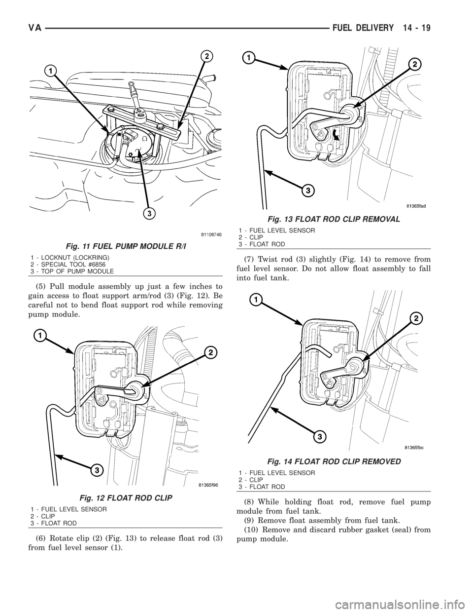
(5) Pull module assembly up just a few inches to
gain access to float support arm/rod (3) (Fig. 12). Be
careful not to bend float support rod while removing
pump module.
(6) Rotate clip (2) (Fig. 13) to release float rod (3)
from fuel level sensor (1).(7) Twist rod (3) slightly (Fig. 14) to remove from
fuel level sensor. Do not allow float assembly to fall
into fuel tank.
(8) While holding float rod, remove fuel pump
module from fuel tank.
(9) Remove float assembly from fuel tank.
(10) Remove and discard rubber gasket (seal) from
pump module.
Fig. 11 FUEL PUMP MODULE R/I
1 - LOCKNUT (LOCKRING)
2 - SPECIAL TOOL #6856
3 - TOP OF PUMP MODULE
Fig. 12 FLOAT ROD CLIP
1 - FUEL LEVEL SENSOR
2 - CLIP
3 - FLOAT ROD
Fig. 13 FLOAT ROD CLIP REMOVAL
1 - FUEL LEVEL SENSOR
2 - CLIP
3 - FLOAT ROD
Fig. 14 FLOAT ROD CLIP REMOVED
1 - FUEL LEVEL SENSOR
2 - CLIP
3 - FLOAT ROD
VAFUEL DELIVERY 14 - 19