2006 MERCEDES-BENZ SPRINTER lock
[x] Cancel search: lockPage 1982 of 2305
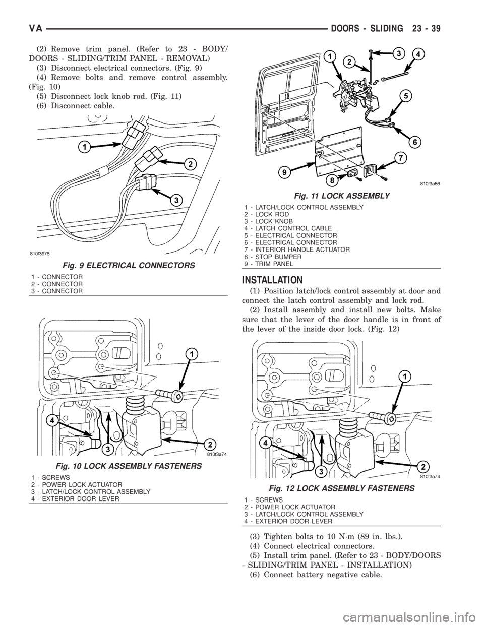
(2) Remove trim panel. (Refer to 23 - BODY/
DOORS - SLIDING/TRIM PANEL - REMOVAL)
(3) Disconnect electrical connectors. (Fig. 9)
(4) Remove bolts and remove control assembly.
(Fig. 10)
(5) Disconnect lock knob rod. (Fig. 11)
(6) Disconnect cable.
INSTALLATION
(1) Position latch/lock control assembly at door and
connect the latch control assembly and lock rod.
(2) Install assembly and install new bolts. Make
sure that the lever of the door handle is in front of
the lever of the inside door lock. (Fig. 12)
(3) Tighten bolts to 10 N´m (89 in. lbs.).
(4) Connect electrical connectors.
(5) Install trim panel. (Refer to 23 - BODY/DOORS
- SLIDING/TRIM PANEL - INSTALLATION)
(6) Connect battery negative cable.
Fig. 9 ELECTRICAL CONNECTORS
1 - CONNECTOR
2 - CONNECTOR
3 - CONNECTOR
Fig. 10 LOCK ASSEMBLY FASTENERS
1 - SCREWS
2 - POWER LOCK ACTUATOR
3 - LATCH/LOCK CONTROL ASSEMBLY
4 - EXTERIOR DOOR LEVER
Fig. 11 LOCK ASSEMBLY
1 - LATCH/LOCK CONTROL ASSEMBLY
2 - LOCK ROD
3 - LOCK KNOB
4 - LATCH CONTROL CABLE
5 - ELECTRICAL CONNECTOR
6 - ELECTRICAL CONNECTOR
7 - INTERIOR HANDLE ACTUATOR
8 - STOP BUMPER
9 - TRIM PANEL
Fig. 12 LOCK ASSEMBLY FASTENERS
1 - SCREWS
2 - POWER LOCK ACTUATOR
3 - LATCH/LOCK CONTROL ASSEMBLY
4 - EXTERIOR DOOR LEVER
VADOORS - SLIDING 23 - 39
Page 1985 of 2305
DISASSEMBLY
(1) Remove door. (Refer to 23 - BODY/DOORS -
SLIDING/REAR LATCH STRIKER - REMOVAL)
(2) Remove inside door handle actuator (7). (Refer
to 23 - BODY/DOORS - SLIDING/INSIDE HANDLE
ACTUATOR - REMOVAL)
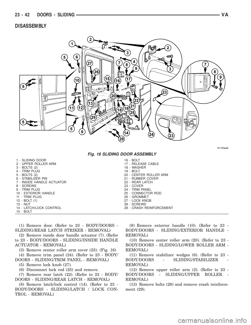
(3) Remove center roller arm cover (23). (Fig. 16)
(4) Remove trim panel (24). (Refer to 23 - BODY/
DOORS - SLIDING/TRIM PANEL - REMOVAL)
(5) Remove lock knob (27).
(6) Disconnect lock rod (25) and remove.
(7) Remove rear latch (22). (Refer to 23 - BODY/
DOORS - SLIDING/REAR LATCH - REMOVAL)
(8) Remove latch/lock control (14). (Refer to 23 -
BODY/DOORS - SLIDING/LATCH / LOCK CON-
TROL - REMOVAL)(9) Remove exterior handle (10). (Refer to 23 -
BODY/DOORS - SLIDING/EXTERIOR HANDLE -
REMOVAL)
(10) Remove center roller arm (20). (Refer to 23 -
BODY/DOORS - SLIDING/LOWER ROLLER ARM -
REMOVAL)
(11) Remove stabilizer wedges (6). (Refer to 23 -
BODY/DOORS - SLIDING/STABILIZER -
REMOVAL)
(12) Remove upper roller arm (2). (Refer to 23 -
BODY/DOORS - SLIDING/UPPER ROLLER -
REMOVAL)
(13) Remove bolts (28) and remove crash reinforce-
ment (29).
Fig. 16 SLIDING DOOR ASSEMBLY
1 - SLIDING DOOR 16 - BOLT
2 - UPPER ROLLER ARM 17 - RELEASE CABLE
3 - BOLTS (2) 18 - WASHER
4 - TRIM PLUG 19 - BOLT
5 - BOLTS (2) 20 - CENTER ROLLER ARM
6 - STABILIZER PIN 21 - RUBBER COVER
7 - INSIDE HANDLE ACTUATOR 22 - REAR LATCH
8 - SCREWS 23 - COVER
9 - TRIM PLUG 24 - TRIM PANEL
10 - EXTERIOR HANDLE 25 - CONNECTOR ROD
11 - TRIM PLUG 26 - GROMMET
12 - BOLT (1) 27 - LOCK KNOB
13 - NUT 28 - SCREWS
14 - LATCH/LOCK CONTROL 29 - CRASH REINFORCEMENT
15 - BOLT
23 - 42 DOORS - SLIDINGVA
Page 1986 of 2305
ASSEMBLY
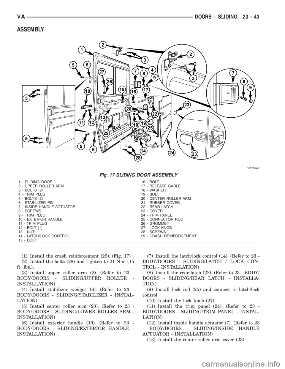
(1) Install the crash reinforcement (29). (Fig. 17)
(2) Install the bolts (28) and tighten to 21 N´m (15
ft. lbs.).
(3) Install upper roller arm (2). (Refer to 23 -
BODY/DOORS - SLIDING/UPPER ROLLER -
INSTALLATION)
(4) Install stabilizer wedges (6). (Refer to 23 -
BODY/DOORS - SLIDING/STABILIZER - INSTAL-
LATION)
(5) Install center roller arm (20). (Refer to 23 -
BODY/DOORS - SLIDING/LOWER ROLLER ARM -
INSTALLATION)
(6) Install exterior handle (10). (Refer to 23 -
BODY/DOORS - SLIDING/EXTERIOR HANDLE -
INSTALLATION)(7) Install the latch/lock control (14). (Refer to 23 -
BODY/DOORS - SLIDING/LATCH / LOCK CON-
TROL - INSTALLATION)
(8) Install the rear latch (22). (Refer to 23 - BODY/
DOORS - SLIDING/REAR LATCH - INSTALLA-
TION)
(9) Install lock rod (25) and connect to latch/lock
control.
(10) Install the lock knob (27).
(11) Install the trim panel (24). (Refer to 23 -
BODY/DOORS - SLIDING/TRIM PANEL - INSTAL-
LATION)
(12) Install inside handle actuator (7). (Refer to 23
- BODY/DOORS - SLIDING/INSIDE HANDLE
ACTUATOR - INSTALLATION)
(13) Install the center roller arm cover (23).
Fig. 17 SLIDING DOOR ASSEMBLY
1 - SLIDING DOOR 16 - BOLT
2 - UPPER ROLLER ARM 17 - RELEASE CABLE
3 - BOLTS (2) 18 - WASHER
4 - TRIM PLUG 19 - BOLT
5 - BOLTS (2) 20 - CENTER ROLLER ARM
6 - STABILIZER PIN 21 - RUBBER COVER
7 - INSIDE HANDLE ACTUATOR 22 - REAR LATCH
8 - SCREWS 23 - COVER
9 - TRIM PLUG 24 - TRIM PANEL
10 - EXTERIOR HANDLE 25 - CONNECTOR ROD
11 - TRIM PLUG 26 - GROMMET
12 - BOLT (1) 27 - LOCK KNOB
13 - NUT 28 - SCREWS
14 - LATCH/LOCK CONTROL 29 - CRASH REINFORCEMENT
15 - BOLT
VADOORS - SLIDING 23 - 43
Page 1989 of 2305
(3) Install wedge and install screws.
(4) Close sliding door to adjust closing wedge.
(5) Open door and tighten screws to 10 N´m (89 in.
lbs.).
TRIM PANEL
REMOVAL
Upper
(1) Remove rivets and remove panel.
Lower
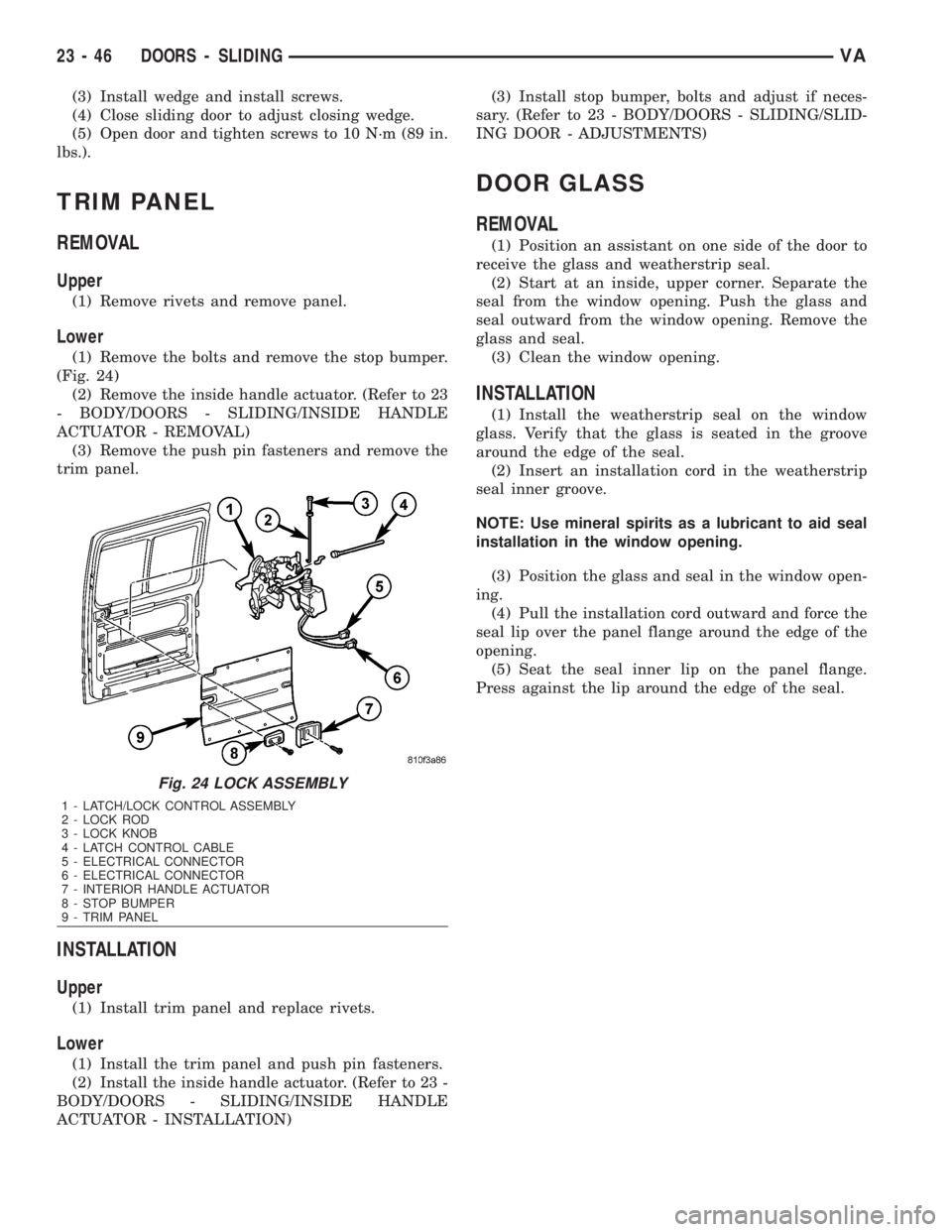
(1) Remove the bolts and remove the stop bumper.
(Fig. 24)
(2) Remove the inside handle actuator. (Refer to 23
- BODY/DOORS - SLIDING/INSIDE HANDLE
ACTUATOR - REMOVAL)
(3) Remove the push pin fasteners and remove the
trim panel.
INSTALLATION
Upper
(1) Install trim panel and replace rivets.
Lower
(1) Install the trim panel and push pin fasteners.
(2) Install the inside handle actuator. (Refer to 23 -
BODY/DOORS - SLIDING/INSIDE HANDLE
ACTUATOR - INSTALLATION)(3) Install stop bumper, bolts and adjust if neces-
sary. (Refer to 23 - BODY/DOORS - SLIDING/SLID-
ING DOOR - ADJUSTMENTS)
DOOR GLASS
REMOVAL
(1) Position an assistant on one side of the door to
receive the glass and weatherstrip seal.
(2) Start at an inside, upper corner. Separate the
seal from the window opening. Push the glass and
seal outward from the window opening. Remove the
glass and seal.
(3) Clean the window opening.
INSTALLATION
(1) Install the weatherstrip seal on the window
glass. Verify that the glass is seated in the groove
around the edge of the seal.
(2) Insert an installation cord in the weatherstrip
seal inner groove.
NOTE: Use mineral spirits as a lubricant to aid seal
installation in the window opening.
(3) Position the glass and seal in the window open-
ing.
(4) Pull the installation cord outward and force the
seal lip over the panel flange around the edge of the
opening.
(5) Seat the seal inner lip on the panel flange.
Press against the lip around the edge of the seal.
Fig. 24 LOCK ASSEMBLY
1 - LATCH/LOCK CONTROL ASSEMBLY
2 - LOCK ROD
3 - LOCK KNOB
4 - LATCH CONTROL CABLE
5 - ELECTRICAL CONNECTOR
6 - ELECTRICAL CONNECTOR
7 - INTERIOR HANDLE ACTUATOR
8 - STOP BUMPER
9 - TRIM PANEL
23 - 46 DOORS - SLIDINGVA
Page 1995 of 2305
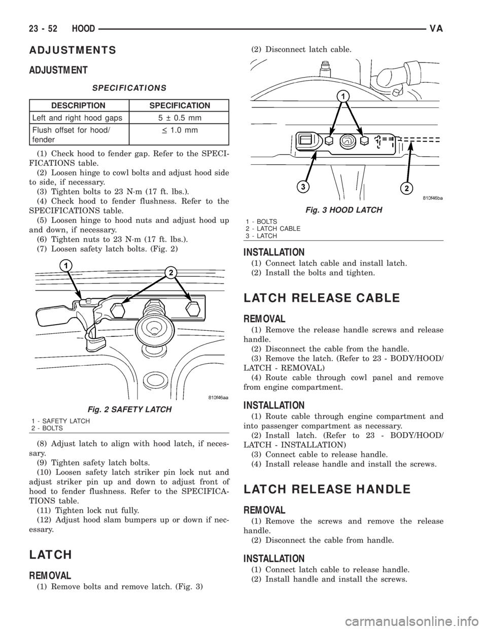
ADJUSTMENTS
ADJUSTMENT
SPECIFICATIONS
DESCRIPTION SPECIFICATION
Left and right hood gaps 5 0.5 mm
Flush offset for hood/
fender·1.0 mm
(1) Check hood to fender gap. Refer to the SPECI-
FICATIONS table.
(2) Loosen hinge to cowl bolts and adjust hood side
to side, if necessary.
(3) Tighten bolts to 23 N´m (17 ft. lbs.).
(4) Check hood to fender flushness. Refer to the
SPECIFICATIONS table.
(5) Loosen hinge to hood nuts and adjust hood up
and down, if necessary.
(6) Tighten nuts to 23 N´m (17 ft. lbs.).
(7) Loosen safety latch bolts. (Fig. 2)
(8) Adjust latch to align with hood latch, if neces-
sary.
(9) Tighten safety latch bolts.
(10) Loosen safety latch striker pin lock nut and
adjust striker pin up and down to adjust front of
hood to fender flushness. Refer to the SPECIFICA-
TIONS table.
(11) Tighten lock nut fully.
(12) Adjust hood slam bumpers up or down if nec-
essary.
LATCH
REMOVAL
(1) Remove bolts and remove latch. (Fig. 3)(2) Disconnect latch cable.
INSTALLATION
(1) Connect latch cable and install latch.
(2) Install the bolts and tighten.
LATCH RELEASE CABLE
REMOVAL
(1) Remove the release handle screws and release
handle.
(2) Disconnect the cable from the handle.
(3) Remove the latch. (Refer to 23 - BODY/HOOD/
LATCH - REMOVAL)
(4) Route cable through cowl panel and remove
from engine compartment.
INSTALLATION
(1) Route cable through engine compartment and
into passenger compartment as necessary.
(2) Install latch. (Refer to 23 - BODY/HOOD/
LATCH - INSTALLATION)
(3) Connect cable to release handle.
(4) Install release handle and install the screws.
LATCH RELEASE HANDLE
REMOVAL
(1) Remove the screws and remove the release
handle.
(2) Disconnect the cable from handle.
INSTALLATION
(1) Connect latch cable to release handle.
(2) Install handle and install the screws.
Fig. 2 SAFETY LATCH
1 - SAFETY LATCH
2 - BOLTS
Fig. 3 HOOD LATCH
1 - BOLTS
2 - LATCH CABLE
3-LATCH
23 - 52 HOODVA
Page 2002 of 2305
INSTRUMENT PANEL ASSEM-
BLY
REMOVAL
WARNING: ON VEHICLES EQUIPPED WITH AIR-
BAGS, DISABLE THE AIRBAG SYSTEM BEFORE
ATTEMPTING ANY STEERING WHEEL, STEERING
COLUMN, SEAT BELT TENSIONER, OR INSTRU-
MENT PANEL COMPONENT DIAGNOSIS OR SER-
VICE. DISCONNECT AND ISOLATE THE BATTERY
NEGATIVE (GROUND) CABLE, THEN WAIT TWO
MINUTES FOR THE AIRBAG SYSTEM CAPACITOR
TO DISCHARGE BEFORE PERFORMING FURTHER
DIAGNOSIS OR SERVICE. THIS IS THE ONLY SURE
WAY TO DISABLE THE AIRBAG SYSTEM. FAILURE
TO TAKE THE PROPER PRECAUTIONS COULD
RESULT IN ACCIDENTAL AIRBAG DEPLOYMENT
AND POSSIBLE PERSONAL INJURY.
²WHEN REMOVING A DEPLOYED AIRBAG, RUB-
BER GLOVES, EYE PROTECTION, AND A LONG-
SLEEVED SHIRT SHOULD BE WORN. THERE MAY
BE DEPOSITS ON THE AIRBAG UNIT AND OTHER
INTERIOR SURFACES. IN LARGE DOSES, THESE
DEPOSITS MAY CAUSE IRRITATION TO THE SKIN
AND EYES.
²USE EXTREME CARE TO PREVENT ANY FOR-
EIGN MATERIAL FROM ENTERING THE PASSEN-
GER AIRBAG, OR BECOMING ENTRAPPED
BETWEEN THE PASSENGER AIRBAG CUSHION
AND THE PASSENGER AIRBAG DOOR. FAILURE TO
OBSERVE THIS WARNING COULD RESULT IN
OCCUPANT INJURIES UPON AIRBAG DEPLOY-
MENT.
²THE PASSENGER AIRBAG DOOR MUST
NEVER BE PAINTED. REPLACEMENT PASSENGER
AIRBAGS ARE SERVICED WITH DOORS IN THE
ORIGINAL COLORS. PAINT MAY CHANGE THE WAY
IN WHICH THE MATERIAL OF THE AIRBAG DOOR
RESPONDS TO AN AIRBAG DEPLOYMENT. FAIL-
URE TO OBSERVE THIS WARNING COULD RESULT
IN OCCUPANT INJURIES UPON AIRBAG DEPLOY-
MENT.
(1) Disconnect and isolate the battery negative
cable.
(2) Remove radio. (Refer to 8 - ELECTRICAL/AU-
DIO/RADIO - REMOVAL)
(3) Remove glove compartment. (Refer to 23 -
BODY/INSTRUMENT PANEL/GLOVE BOX -
REMOVAL)
(4) Remove cup holder. (Refer to 23 - BODY/IN-
STRUMENT PANEL/CUP HOLDER - REMOVAL)
(5) Remove instrument cluster. (Refer to 8 - ELEC-
TRICAL/INSTRUMENT CLUSTER - REMOVAL)(6) Remove passenger airbag. (Refer to 8 - ELEC-
TRICAL/RESTRAINTS/PASSENGER AIRBAG -
REMOVAL)
(7) Remove right and left speakers. (Refer to 8 -
ELECTRICAL/AUDIO/SPEAKER - REMOVAL)
(8) Remove center bezel. (Refer to 23 - BODY/IN-
STRUMENT PANEL/INSTRUMENT PANEL CEN-
TER BEZEL - REMOVAL)
(9) Remove air conditioning push-button control
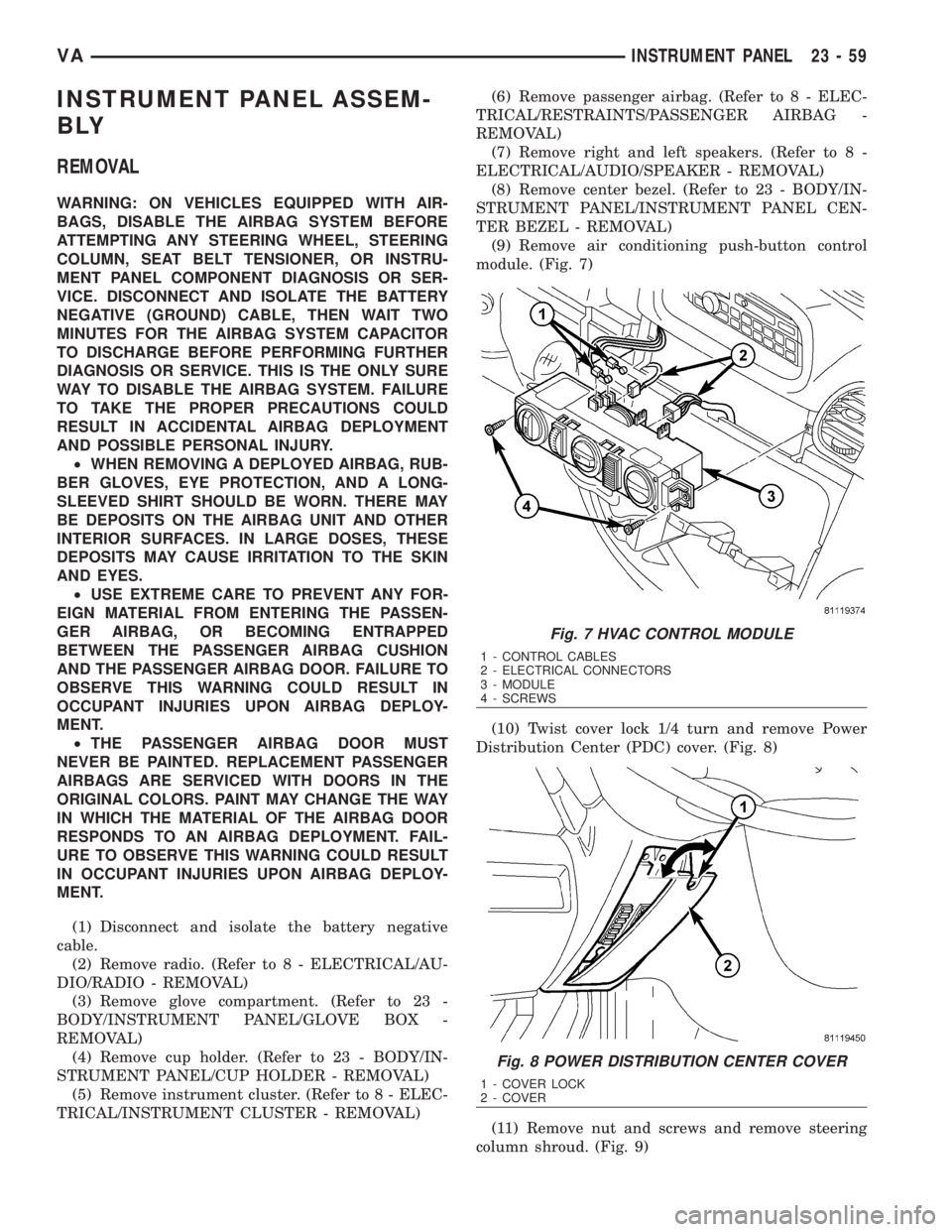
module. (Fig. 7)
(10) Twist cover lock 1/4 turn and remove Power
Distribution Center (PDC) cover. (Fig. 8)
(11) Remove nut and screws and remove steering
column shroud. (Fig. 9)
Fig. 7 HVAC CONTROL MODULE
1 - CONTROL CABLES
2 - ELECTRICAL CONNECTORS
3 - MODULE
4 - SCREWS
Fig. 8 POWER DISTRIBUTION CENTER COVER
1 - COVER LOCK
2 - COVER
VAINSTRUMENT PANEL 23 - 59
Page 2005 of 2305
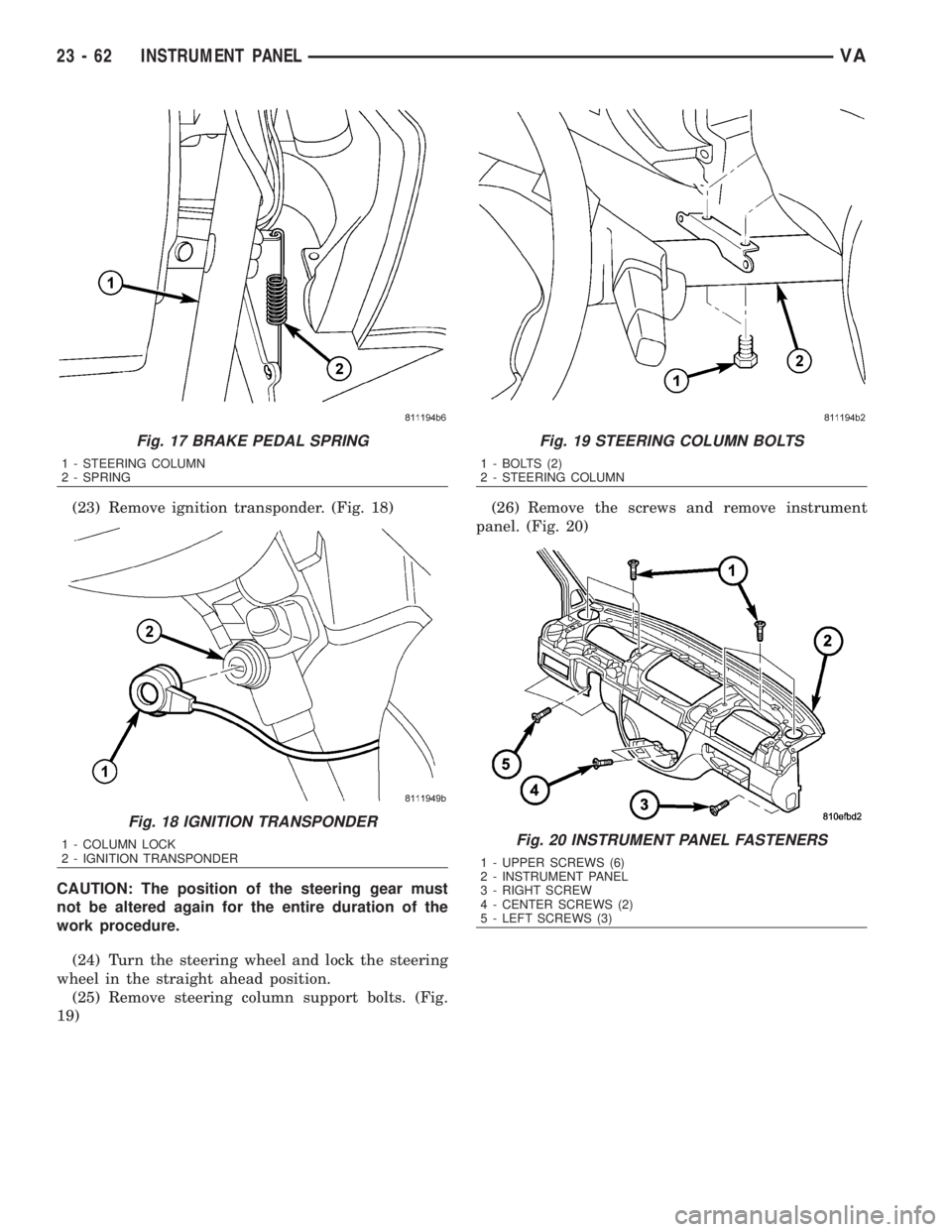
(23) Remove ignition transponder. (Fig. 18)
CAUTION: The position of the steering gear must
not be altered again for the entire duration of the
work procedure.
(24) Turn the steering wheel and lock the steering
wheel in the straight ahead position.
(25) Remove steering column support bolts. (Fig.
19)(26) Remove the screws and remove instrument
panel. (Fig. 20)
Fig. 17 BRAKE PEDAL SPRING
1 - STEERING COLUMN
2 - SPRING
Fig. 18 IGNITION TRANSPONDER
1 - COLUMN LOCK
2 - IGNITION TRANSPONDER
Fig. 19 STEERING COLUMN BOLTS
1 - BOLTS (2)
2 - STEERING COLUMN
Fig. 20 INSTRUMENT PANEL FASTENERS
1 - UPPER SCREWS (6)
2 - INSTRUMENT PANEL
3 - RIGHT SCREW
4 - CENTER SCREWS (2)
5 - LEFT SCREWS (3)
23 - 62 INSTRUMENT PANELVA
Page 2006 of 2305
INSTALLATION
WARNING: ON VEHICLES EQUIPPED WITH AIR-
BAGS, DISABLE THE AIRBAG SYSTEM BEFORE
ATTEMPTING ANY STEERING WHEEL, STEERING
COLUMN, SEAT BELT TENSIONER, OR INSTRU-
MENT PANEL COMPONENT DIAGNOSIS OR SER-
VICE. DISCONNECT AND ISOLATE THE BATTERY
NEGATIVE (GROUND) CABLE, THEN WAIT TWO
MINUTES FOR THE AIRBAG SYSTEM CAPACITOR
TO DISCHARGE BEFORE PERFORMING FURTHER
DIAGNOSIS OR SERVICE. THIS IS THE ONLY SURE
WAY TO DISABLE THE AIRBAG SYSTEM. FAILURE
TO TAKE THE PROPER PRECAUTIONS COULD
RESULT IN ACCIDENTAL AIRBAG DEPLOYMENT
AND POSSIBLE PERSONAL INJURY.
²WHEN REMOVING A DEPLOYED AIRBAG, RUB-
BER GLOVES, EYE PROTECTION, AND A LONG-
SLEEVED SHIRT SHOULD BE WORN. THERE MAY
BE DEPOSITS ON THE AIRBAG UNIT AND OTHER
INTERIOR SURFACES. IN LARGE DOSES, THESE
DEPOSITS MAY CAUSE IRRITATION TO THE SKIN
AND EYES.
²USE EXTREME CARE TO PREVENT ANY FOR-
EIGN MATERIAL FROM ENTERING THE PASSEN-
GER AIRBAG, OR BECOMING ENTRAPPED
BETWEEN THE PASSENGER AIRBAG CUSHION
AND THE PASSENGER AIRBAG DOOR. FAILURE TO
OBSERVE THIS WARNING COULD RESULT IN
OCCUPANT INJURIES UPON AIRBAG DEPLOY-
MENT.
²THE PASSENGER AIRBAG DOOR MUST
NEVER BE PAINTED. REPLACEMENT PASSENGER
AIRBAGS ARE SERVICED WITH DOORS IN THE
ORIGINAL COLORS. PAINT MAY CHANGE THE WAY
IN WHICH THE MATERIAL OF THE AIRBAG DOOR
RESPONDS TO AN AIRBAG DEPLOYMENT. FAIL-
URE TO OBSERVE THIS WARNING COULD RESULT
IN OCCUPANT INJURIES UPON AIRBAG DEPLOY-
MENT.
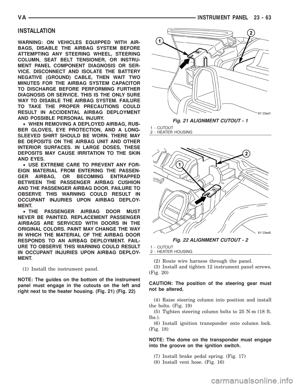
(1) Install the instrument panel.
NOTE: The guides on the bottom of the instrument
panel must engage in the cutouts on the left and
right next to the heater housing. (Fig. 21) (Fig. 22)(2) Route wire harness through the panel.
(3) Install and tighten 12 instrument panel screws.
(Fig. 20)
CAUTION: The position of the steering gear must
not be altered.
(4) Raise steering column into position and install
the bolts. (Fig. 19)
(5) Tighten steering column bolts to 25 N´m (18 ft.
lbs.).
(6) Install ignition transponder onto column lock.
(Fig. 18)
NOTE: The dome on the transponder must engage
into the groove on the ignition switch.
(7) Install brake pedal spring. (Fig. 17)
(8) Install vent hose. (Fig. 16)
Fig. 21 ALIGNMENT CUTOUT - 1
1 - CUTOUT
2 - HEATER HOUSING
Fig. 22 ALIGNMENT CUTOUT - 2
1 - CUTOUT
2 - HEATER HOUSING
VAINSTRUMENT PANEL 23 - 63