2006 MERCEDES-BENZ SPRINTER lock
[x] Cancel search: lockPage 2056 of 2305
BLOWER MOTOR SWITCH
DESCRIPTION
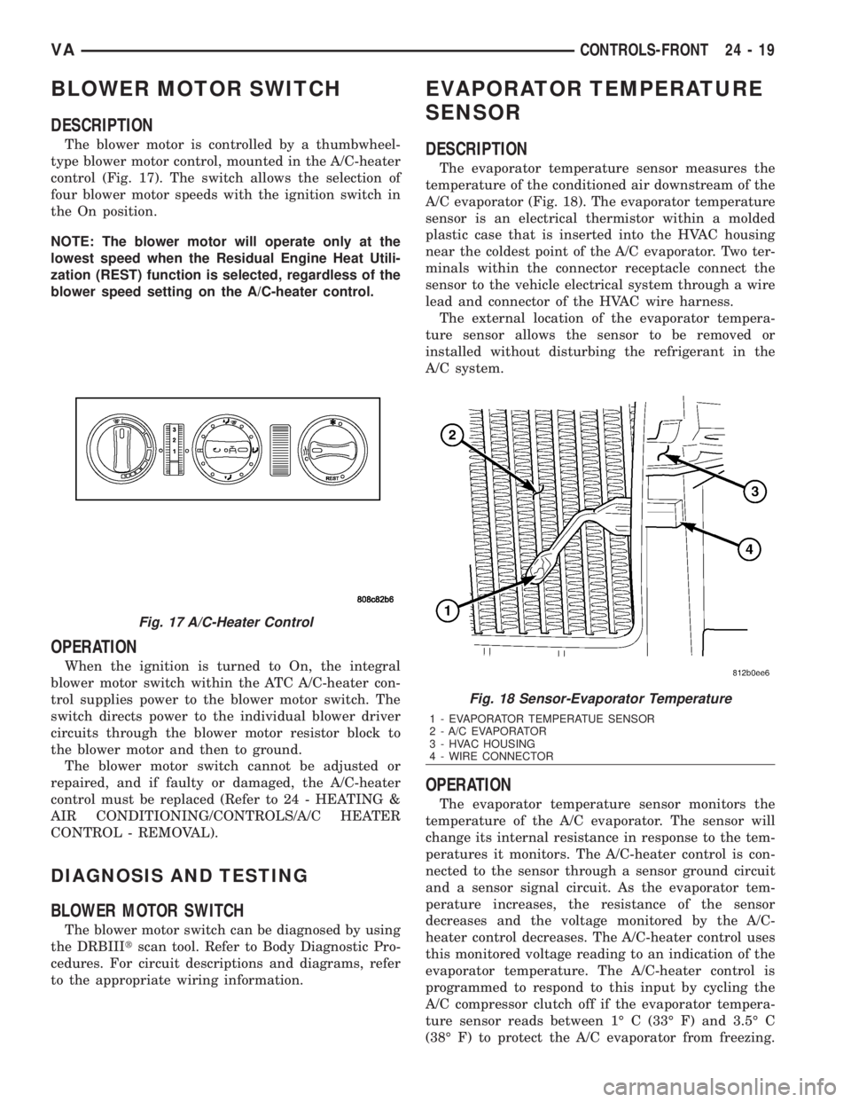
The blower motor is controlled by a thumbwheel-
type blower motor control, mounted in the A/C-heater
control (Fig. 17). The switch allows the selection of
four blower motor speeds with the ignition switch in
the On position.
NOTE: The blower motor will operate only at the
lowest speed when the Residual Engine Heat Utili-
zation (REST) function is selected, regardless of the
blower speed setting on the A/C-heater control.
OPERATION
When the ignition is turned to On, the integral
blower motor switch within the ATC A/C-heater con-
trol supplies power to the blower motor switch. The
switch directs power to the individual blower driver
circuits through the blower motor resistor block to
the blower motor and then to ground.
The blower motor switch cannot be adjusted or
repaired, and if faulty or damaged, the A/C-heater
control must be replaced (Refer to 24 - HEATING &
AIR CONDITIONING/CONTROLS/A/C HEATER
CONTROL - REMOVAL).
DIAGNOSIS AND TESTING
BLOWER MOTOR SWITCH
The blower motor switch can be diagnosed by using
the DRBIIItscan tool. Refer to Body Diagnostic Pro-
cedures. For circuit descriptions and diagrams, refer
to the appropriate wiring information.
EVAPORATOR TEMPERATURE
SENSOR
DESCRIPTION
The evaporator temperature sensor measures the
temperature of the conditioned air downstream of the
A/C evaporator (Fig. 18). The evaporator temperature
sensor is an electrical thermistor within a molded
plastic case that is inserted into the HVAC housing
near the coldest point of the A/C evaporator. Two ter-
minals within the connector receptacle connect the
sensor to the vehicle electrical system through a wire
lead and connector of the HVAC wire harness.
The external location of the evaporator tempera-
ture sensor allows the sensor to be removed or
installed without disturbing the refrigerant in the
A/C system.
OPERATION
The evaporator temperature sensor monitors the
temperature of the A/C evaporator. The sensor will
change its internal resistance in response to the tem-
peratures it monitors. The A/C-heater control is con-
nected to the sensor through a sensor ground circuit
and a sensor signal circuit. As the evaporator tem-
perature increases, the resistance of the sensor
decreases and the voltage monitored by the A/C-
heater control decreases. The A/C-heater control uses
this monitored voltage reading to an indication of the
evaporator temperature. The A/C-heater control is
programmed to respond to this input by cycling the
A/C compressor clutch off if the evaporator tempera-
ture sensor reads between 1É C (33É F) and 3.5É C
(38É F) to protect the A/C evaporator from freezing.
Fig. 17 A/C-Heater Control
Fig. 18 Sensor-Evaporator Temperature
1 - EVAPORATOR TEMPERATUE SENSOR
2 - A/C EVAPORATOR
3 - HVAC HOUSING
4 - WIRE CONNECTOR
VACONTROLS-FRONT 24 - 19
Page 2059 of 2305
NOTE: While holding the A/C-heater control in the
installation position, verify that the control cables
are not twisted.
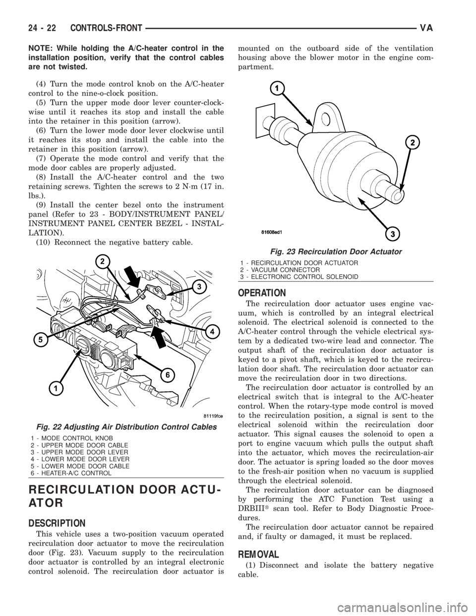
(4) Turn the mode control knob on the A/C-heater
control to the nine-o-clock position.
(5) Turn the upper mode door lever counter-clock-
wise until it reaches its stop and install the cable
into the retainer in this position (arrow).
(6) Turn the lower mode door lever clockwise until
it reaches its stop and install the cable into the
retainer in this position (arrow).
(7) Operate the mode control and verify that the
mode door cables are properly adjusted.
(8) Install the A/C-heater control and the two
retaining screws. Tighten the screws to 2 N´m (17 in.
lbs.).
(9) Install the center bezel onto the instrument
panel (Refer to 23 - BODY/INSTRUMENT PANEL/
INSTRUMENT PANEL CENTER BEZEL - INSTAL-
LATION).
(10) Reconnect the negative battery cable.
RECIRCULATION DOOR ACTU-
ATOR
DESCRIPTION
This vehicle uses a two-position vacuum operated
recirculation door actuator to move the recirculation
door (Fig. 23). Vacuum supply to the recirculation
door actuator is controlled by an integral electronic
control solenoid. The recirculation door actuator ismounted on the outboard side of the ventilation
housing above the blower motor in the engine com-
partment.
OPERATION
The recirculation door actuator uses engine vac-
uum, which is controlled by an integral electrical
solenoid. The electrical solenoid is connected to the
A/C-heater control through the vehicle electrical sys-
tem by a dedicated two-wire lead and connector. The
output shaft of the recirculation door actuator is
keyed to a pivot shaft, which is keyed to the recircu-
lation door shaft. The recirculation door actuator can
move the recirculation door in two directions.
The recirculation door actuator is controlled by an
electrical switch that is integral to the A/C-heater
control. When the rotary-type mode control is moved
to the recirculation position, a signal is sent to the
electrical solenoid within the recirculation door
actuator. This signal causes the solenoid to open a
port to engine vacuum which pulls the output shaft
into the actuator, which moves the recirculation-air
door. The actuator is spring loaded so the door moves
to the fresh-air position when no vacuum is supplied
through the electrical solenoid.
The recirculation door actuator can be diagnosed
by performing the ATC Function Test using a
DRBIIItscan tool. Refer to Body Diagnostic Proce-
dures.
The recirculation door actuator cannot be repaired
and, if faulty or damaged, it must be replaced.
REMOVAL
(1) Disconnect and isolate the battery negative
cable.
Fig. 22 Adjusting Air Distribution Control Cables
1 - MODE CONTROL KNOB
2 - UPPER MODE DOOR CABLE
3 - UPPER MODE DOOR LEVER
4 - LOWER MODE DOOR LEVER
5 - LOWER MODE DOOR CABLE
6 - HEATER-A/C CONTROL
Fig. 23 Recirculation Door Actuator
1 - RECIRCULATION DOOR ACTUATOR
2 - VACUUM CONNECTOR
3 - ELECTRONIC CONTROL SOLENOID
24 - 22 CONTROLS-FRONTVA
Page 2061 of 2305
CONTROLS - REAR
TABLE OF CONTENTS
page page
A/C CLUTCH RELAY
DESCRIPTION.........................24
OPERATION...........................25
REMOVAL.............................25
INSTALLATION.........................26
A/C CONDENSER FAN RELAY
DESCRIPTION.........................26
OPERATION...........................26
REMOVAL.............................27
INSTALLATION.........................28
A/C CONTROL MODULE
DESCRIPTION.........................28
OPERATION...........................28
REMOVAL.............................29
INSTALLATION.........................30
A/C HIGH PRESSURE SWITCH
DESCRIPTION.........................30
OPERATION...........................30
REMOVAL.............................31
INSTALLATION.........................31
A/C LOW PRESSURE SWITCH
DESCRIPTION.........................32
OPERATION...........................32
REMOVAL.............................32
INSTALLATION.........................33
BLOWER MOTOR RELAY
DESCRIPTION.........................33
OPERATION...........................33
REMOVAL.............................34
INSTALLATION.........................35
BLOWER MOTOR SWITCH
DESCRIPTION.........................35
OPERATION...........................35
DIAGNOSIS AND TESTING
REAR BLOWER MOTOR SWITCH.........36REMOVAL.............................36
INSTALLATION.........................37
EVAPORATOR TEMPERATURE SENSOR
DESCRIPTION.........................37
OPERATION...........................37
REMOVAL.............................37
INSTALLATION.........................38
TEMPERATURE CONTROL
DESCRIPTION.........................38
OPERATION...........................38
DIAGNOSIS AND TESTING
REAR A/C TEMPERATURE CONTROL.....39
REMOVAL.............................39
INSTALLATION.........................40
TEMPERATURE SENSOR
DESCRIPTION.........................40
OPERATION...........................40
DIAGNOSIS AND TESTING
REAR TEMPERATURE SENSOR..........40
REMOVAL.............................40
INSTALLATION.........................41
SUPPRESSOR FILTER - REAR BLOWER
MOTOR
DESCRIPTION.........................41
OPERATION...........................41
REMOVAL.............................42
INSTALLATION.........................43
SUPPRESSOR FILTER - REAR CONDENSER
FA N
DESCRIPTION.........................43
OPERATION...........................44
REMOVAL.............................44
INSTALLATION.........................44
A / C CLUTCH RELAY
DESCRIPTION
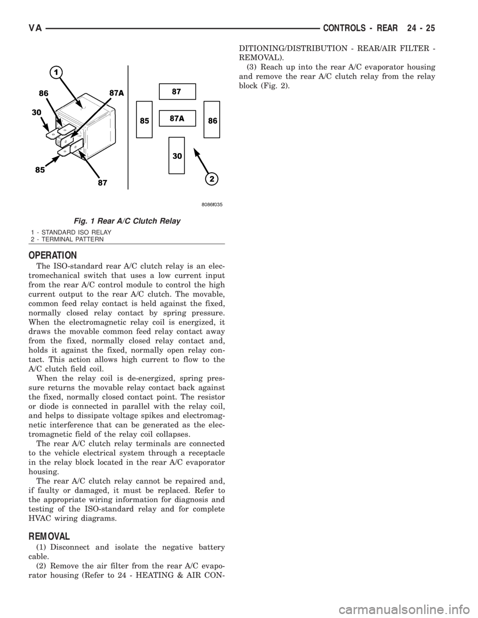
The rear A/C clutch relay for the rear A/C system
is an International Standards Organization (ISO)-
type relay (Fig. 1). Relays conforming to the ISO
specifications have common physical dimensions, cur-
rent capacities, terminal functions and patterns. The
rear A/C clutch relay is an electromechanical device
that uses a low current input controlled by the rear
A/C control module to control the high current output
to the A/C clutch field coil for the rear A/C system.The rear A/C clutch relay is located in the relay
block in the rear A/C evaporator housing.
24 - 24 CONTROLS - REARVA
Page 2062 of 2305
OPERATION
The ISO-standard rear A/C clutch relay is an elec-
tromechanical switch that uses a low current input
from the rear A/C control module to control the high
current output to the rear A/C clutch. The movable,
common feed relay contact is held against the fixed,
normally closed relay contact by spring pressure.
When the electromagnetic relay coil is energized, it
draws the movable common feed relay contact away
from the fixed, normally closed relay contact and,
holds it against the fixed, normally open relay con-
tact. This action allows high current to flow to the
A/C clutch field coil.
When the relay coil is de-energized, spring pres-
sure returns the movable relay contact back against
the fixed, normally closed contact point. The resistor
or diode is connected in parallel with the relay coil,
and helps to dissipate voltage spikes and electromag-
netic interference that can be generated as the elec-
tromagnetic field of the relay coil collapses.
The rear A/C clutch relay terminals are connected
to the vehicle electrical system through a receptacle
in the relay block located in the rear A/C evaporator
housing.
The rear A/C clutch relay cannot be repaired and,
if faulty or damaged, it must be replaced. Refer to
the appropriate wiring information for diagnosis and
testing of the ISO-standard relay and for complete
HVAC wiring diagrams.
REMOVAL
(1) Disconnect and isolate the negative battery
cable.
(2) Remove the air filter from the rear A/C evapo-
rator housing (Refer to 24 - HEATING & AIR CON-DITIONING/DISTRIBUTION - REAR/AIR FILTER -
REMOVAL).
(3) Reach up into the rear A/C evaporator housing
and remove the rear A/C clutch relay from the relay
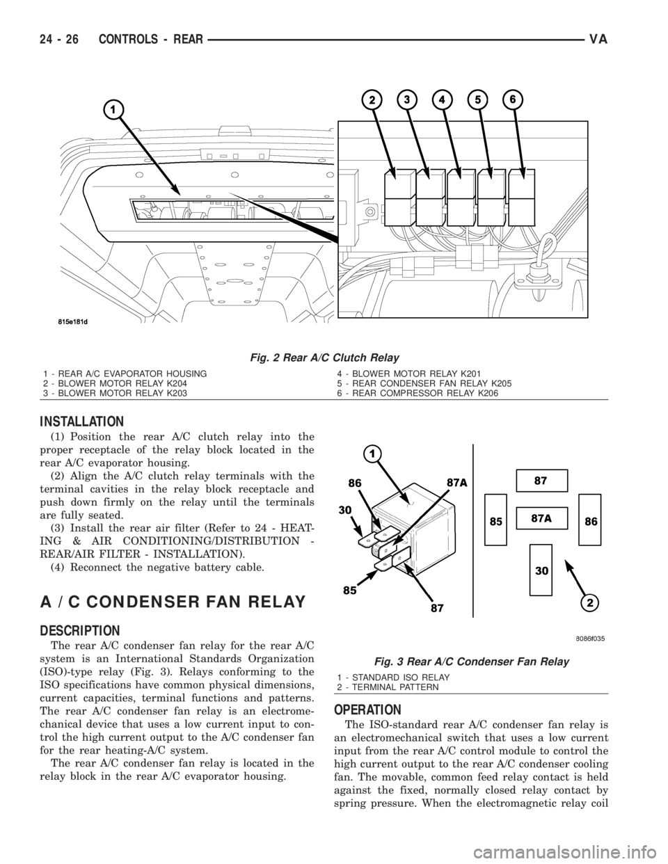
block (Fig. 2).
Fig. 1 Rear A/C Clutch Relay
1 - STANDARD ISO RELAY
2 - TERMINAL PATTERN
VACONTROLS - REAR 24 - 25
Page 2063 of 2305
INSTALLATION
(1) Position the rear A/C clutch relay into the
proper receptacle of the relay block located in the
rear A/C evaporator housing.
(2) Align the A/C clutch relay terminals with the
terminal cavities in the relay block receptacle and
push down firmly on the relay until the terminals
are fully seated.
(3) Install the rear air filter (Refer to 24 - HEAT-
ING & AIR CONDITIONING/DISTRIBUTION -
REAR/AIR FILTER - INSTALLATION).
(4) Reconnect the negative battery cable.
A / C CONDENSER FAN RELAY
DESCRIPTION
The rear A/C condenser fan relay for the rear A/C
system is an International Standards Organization
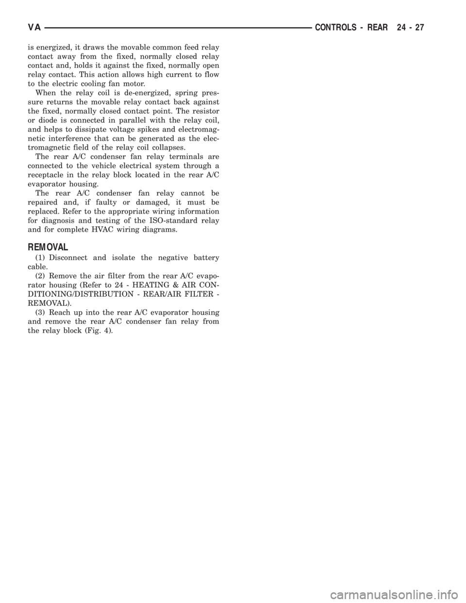
(ISO)-type relay (Fig. 3). Relays conforming to the
ISO specifications have common physical dimensions,
current capacities, terminal functions and patterns.
The rear A/C condenser fan relay is an electrome-
chanical device that uses a low current input to con-
trol the high current output to the A/C condenser fan
for the rear heating-A/C system.
The rear A/C condenser fan relay is located in the
relay block in the rear A/C evaporator housing.
OPERATION
The ISO-standard rear A/C condenser fan relay is
an electromechanical switch that uses a low current
input from the rear A/C control module to control the
high current output to the rear A/C condenser cooling
fan. The movable, common feed relay contact is held
against the fixed, normally closed relay contact by
spring pressure. When the electromagnetic relay coil
Fig. 2 Rear A/C Clutch Relay
1 - REAR A/C EVAPORATOR HOUSING
2 - BLOWER MOTOR RELAY K204
3 - BLOWER MOTOR RELAY K2034 - BLOWER MOTOR RELAY K201
5 - REAR CONDENSER FAN RELAY K205
6 - REAR COMPRESSOR RELAY K206
Fig. 3 Rear A/C Condenser Fan Relay
1 - STANDARD ISO RELAY
2 - TERMINAL PATTERN
24 - 26 CONTROLS - REARVA
Page 2064 of 2305
is energized, it draws the movable common feed relay
contact away from the fixed, normally closed relay
contact and, holds it against the fixed, normally open
relay contact. This action allows high current to flow
to the electric cooling fan motor.
When the relay coil is de-energized, spring pres-
sure returns the movable relay contact back against
the fixed, normally closed contact point. The resistor
or diode is connected in parallel with the relay coil,
and helps to dissipate voltage spikes and electromag-
netic interference that can be generated as the elec-
tromagnetic field of the relay coil collapses.
The rear A/C condenser fan relay terminals are
connected to the vehicle electrical system through a
receptacle in the relay block located in the rear A/C
evaporator housing.
The rear A/C condenser fan relay cannot be
repaired and, if faulty or damaged, it must be
replaced. Refer to the appropriate wiring information
for diagnosis and testing of the ISO-standard relay
and for complete HVAC wiring diagrams.
REMOVAL
(1) Disconnect and isolate the negative battery
cable.
(2) Remove the air filter from the rear A/C evapo-
rator housing (Refer to 24 - HEATING & AIR CON-
DITIONING/DISTRIBUTION - REAR/AIR FILTER -
REMOVAL).
(3) Reach up into the rear A/C evaporator housing
and remove the rear A/C condenser fan relay from
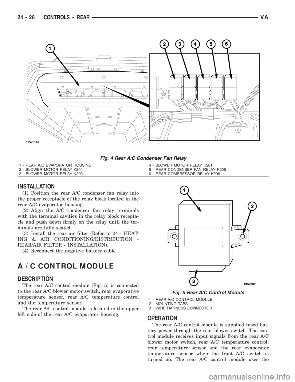
the relay block (Fig. 4).
VACONTROLS - REAR 24 - 27
Page 2065 of 2305
INSTALLATION
(1) Position the rear A/C condenser fan relay into
the proper receptacle of the relay block located in the
rear A/C evaporator housing.
(2) Align the A/C condenser fan relay terminals
with the terminal cavities in the relay block recepta-
cle and push down firmly on the relay until the ter-
minals are fully seated.
(3) Install the rear air filter (Refer to 24 - HEAT-
ING & AIR CONDITIONING/DISTRIBUTION -
REAR/AIR FILTER - INSTALLATION).
(4) Reconnect the negative battery cable.
A / C CONTROL MODULE
DESCRIPTION
The rear A/C control module (Fig. 5) is connected
to the rear A/C blower motor switch, rear evaporative
temperature sensor, rear A/C temperature control
and the temperature sensor.
The rear A/C control module is located in the upper
left side of the rear A/C evaporator housing.
OPERATION
The rear A/C control module is supplied fused bat-
tery power through the rear blower switch. The con-
trol module receives input signals from the rear A/C
blower motor switch, rear A/C temperature control,
rear temperature sensor and the rear evaporator
temperature sensor when the front A/C switch is
turned on. The rear A/C control module uses the
Fig. 4 Rear A/C Condenser Fan Relay
1 - REAR A/C EVAPORATOR HOUSING
2 - BLOWER MOTOR RELAY K204
3 - BLOWER MOTOR RELAY K2034 - BLOWER MOTOR RELAY K201
5 - REAR CONDENSER FAN RELAY K205
6 - REAR COMPRESSOR RELAY K206
Fig. 5 Rear A/C Control Module
1 - REAR A/C CONTROL MODULE
2 - MOUNTING TABS
3 - WIRE HARNESS CONNECTOR
24 - 28 CONTROLS - REARVA
Page 2070 of 2305
INSTALLATION
NOTE: Replacement of the PTFE thread sealing
tape is required anytime the rear A/C low pressure
switch is removed from the rear suction line line.
Failure to replace the sealing tape could result in a
rear refrigerant system leak.
(1) Remove the tape or plug from the rear suction
line fitting.
(2) Install PTFE thread sealing tape onto the rear
A/C low pressure switch and install the switch onto
the rear suction line. Tightened the A/C low pressure
switch to 10 N´m (88 in. lbs.).
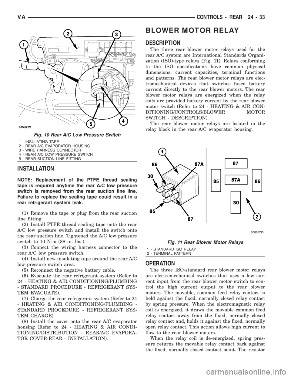
(3) Connect the wiring harness connector to the
rear A/C low pressure switch.
(4) Install new insulating tape around the rear A/C
low pressure switch area.
(5) Reconnect the negative battery cable.
(6) Evacuate the rear refrigerant system (Refer to
24 - HEATING & AIR CONDITIONING/PLUMBING
- STANDARD PROCEDURE - REFRIGERANT SYS-
TEM EVACUATE).
(7) Charge the rear refrigerant system (Refer to 24
- HEATING & AIR CONDITIONING/PLUMBING -
STANDARD PROCEDURE - REFRIGERANT SYS-
TEM CHARGE).
(8) Install the cover onto the rear A/C evaporator
housing (Refer to 24 - HEATING & AIR CONDI-
TIONING/DISTRIBUTION - REAR/A/C EVAPORA-
TOR COVER-REAR - INSTALLATION).
BLOWER MOTOR RELAY
DESCRIPTION
The three rear blower motor relays used for the
rear A/C system are International Standards Organi-
zation (ISO)-type relays (Fig. 11). Relays conforming
to the ISO specifications have common physical
dimensions, current capacities, terminal functions
and patterns. The rear blower motor relays are elec-
tromechanical devices that switches fused battery
current directly to the rear blower motors. The rear
blower motor relays are energized when the relay
coils are provided battery current by the rear blower
motor switch (Refer to 24 - HEATING & AIR CON-
DITIONING/CONTROLS/BLOWER MOTOR
SWITCH - DESCRIPTION).
The rear blower motor relays are located in the
relay block in the rear A/C evaporator housing.
OPERATION
The three ISO-standard rear blower motor relays
are electromechanical switches that uses a low cur-
rent input from the rear blower motor switch to con-
trol the high current output to the rear blower
motors. The movable, common feed relay contact is
held against the fixed, normally closed relay contact
by spring pressure. When the electromagnetic relay
coil is energized, it draws the movable common feed
relay contact away from the fixed, normally closed
relay contact and, holds it against the fixed, normally
open relay contact. This action allows high current to
flow to the rear blower motors.
When the relay coil is de-energized, spring pres-
sure returns the movable relay contact back against
the fixed, normally closed contact point. The resistor
Fig. 10 Rear A/C Low Pressure Switch
1 - INSULATING TAPE
2 - REAR A/C EVAPORATOR HOUSING
3 - WIRE HARNESS CONNECTOR
4 - REAR A/C LOW PRESSURE SWITCH
5 - REAR SUCTION LINE FITTING
Fig. 11 Rear Blower Motor Relays
1 - STANDARD ISO RELAY
2 - TERMINAL PATTERN
VACONTROLS - REAR 24 - 33