2006 MERCEDES-BENZ SPRINTER lock
[x] Cancel search: lockPage 2137 of 2305
CAUTION: Use only the specified O-rings as they
are made of a special material for the R-134a sys-
tem. The use of any other O-rings may allow the
connection to leak intermittently during vehicle
operation.
(4) Lubricate the male fitting and O-rings, and the
inside of the female fitting with clean R-134a refrig-
erant oil. Use only refrigerant oil of the type recom-
mended for the compressor in the vehicle.
(5) Fit the female half of the coupler fitting over
the male half of the fitting.
(6) Push together firmly on the two halves of the
coupler fitting until the garter spring in the cage on
the male half of the fitting snaps over the flanged
end on the female half of the fitting.
(7) Ensure that the spring-lock coupler is fully
engaged by trying to separate the two coupler halves.
This is done by pulling the refrigerant lines on either
side of the coupler away from each other.
(8) Reinstall the secondary retaining clip over the
spring-lock coupler cage.
(9) Evacuate the refrigerant system (Refer to 24 -
HEATING & AIR CONDITIONING/PLUMBING -
STANDARD PROCEDURE - REFRIGERANT SYS-
TEM EVACUATE).
(10) Charge the refrigerant system (Refer to 24 -
HEATING & AIR CONDITIONING/PLUMBING -
STANDARD PROCEDURE - REFRIGERANT SYS-
TEM CHARGE).
UNDERBODY LINES
REMOVAL
WARNING: Refer to the applicable warnings and
cautions for this system before performing the fol-
lowing operation (Refer to 24 - HEATING & AIR
CONDITIONING/PLUMBING - WARNINGS) and (Refer
to 24 - HEATING & AIR CONDITIONING/PLUMBING -
CAUTIONS). Failure to follow the warnings and cau-
tions could result in possible personal injury or
death.
NOTE: The underbody refrigerant lines for the
optional rear A/C system are serviced in five sec-
tions. Two sections are connected the A/C compres-
sor. Two sections of the underbody suction line
(low-side) are connected together by a tapping
block with an O-ring seal. The underbody A/C dis-
charge line uses a spring-lock type refrigerant line
coupler with an O-ring seal.
DISCHARGE LINE
(1) Remove the cover from the rear A/C evaporator
housing (Refer to 24 - HEATING & AIR CONDI-TIONING/DISTRIBUTION - REAR/A/C EVAPORA-
TOR COVER-REAR - REMOVAL).
(2) Recover the refrigerant from the rear refriger-
ant system (Refer to 24 - HEATING & AIR CONDI-
TIONING/PLUMBING - STANDARD PROCEDURE -
REFRIGERANT RECOVERY).
(3) Raise and support the vehicle.
(4) Using the proper A/C line disconnect tool, dis-
connect the underbody discharge line spring-lock cou-
pler from the compressor section of the underbody
discharge line and remove and discard the O-ring
seal (Refer to 24 - HEATING & AIR CONDITION-
ING/PLUMBING/REFRIGERANT LINE COUPLER -
REMOVAL) (Fig. 39).
(5) Disconnect the underbody discharge line from
the rear A/C discharge line and remove and discard
the O-ring seal.
(6) Install plug in, or tape over all of the opened
discharge line fittings.
(7) Disengage the fuel lines from the retaining clip
located near the transmission and position the fuel
lines out of the way.
(8) Remove the screws and brackets that secure
the discharge line to the underneath of the vehicle.
(9) Support transmission with a suitable lifting
device and remove the rear transmission crossmem-
ber (Refer to 13 - FRAME & BUMPERS/FRAME/
REAR CROSSMEMBER-TRANSMISSION -
REMOVAL).
(10) Remove the underbody discharge line from
the vehicle. Push the discharge line forward and over
the transmission, then pull it rearward to remove.
(11) If necessary, remove the bolt that secures the
compressor section of the underbody discharge line to
the A/C compressor and remove and discard the
O-ring seal. Make sure to plug in, or tape over the
opened discharge line fitting and compressor port.
24 - 100 PLUMBINGVA
Page 2139 of 2305
SUCTION LINE - REAR SECTION
(1) Remove the cover from the rear A/C evaporator
housing (Refer to 24 - HEATING & AIR CONDI-
TIONING/DISTRIBUTION - REAR/A/C EVAPORA-
TOR COVER-REAR - REMOVAL).
(2) Recover the refrigerant from the rear refriger-
ant system (Refer to 24 - HEATING & AIR CONDI-
TIONING/PLUMBING - STANDARD PROCEDURE -
REFRIGERANT RECOVERY).
(3) Raise and support the vehicle.
(4) Remove the bolt that secures the connection of
the front section of the underbody suction line to the
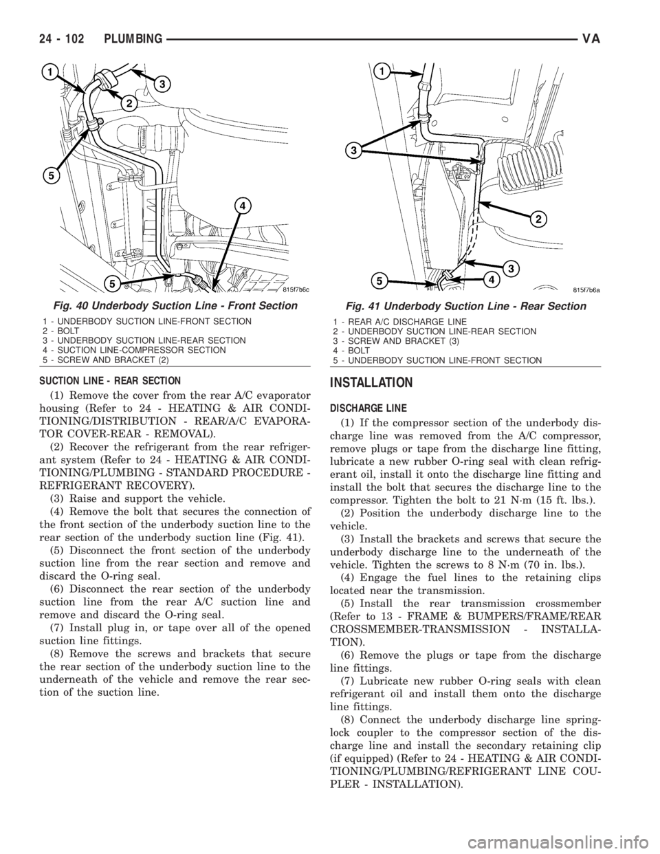
rear section of the underbody suction line (Fig. 41).
(5) Disconnect the front section of the underbody
suction line from the rear section and remove and
discard the O-ring seal.
(6) Disconnect the rear section of the underbody
suction line from the rear A/C suction line and
remove and discard the O-ring seal.
(7) Install plug in, or tape over all of the opened
suction line fittings.
(8) Remove the screws and brackets that secure
the rear section of the underbody suction line to the
underneath of the vehicle and remove the rear sec-
tion of the suction line.INSTALLATION
DISCHARGE LINE
(1) If the compressor section of the underbody dis-
charge line was removed from the A/C compressor,
remove plugs or tape from the discharge line fitting,
lubricate a new rubber O-ring seal with clean refrig-
erant oil, install it onto the discharge line fitting and
install the bolt that secures the discharge line to the
compressor. Tighten the bolt to 21 N´m (15 ft. lbs.).
(2) Position the underbody discharge line to the
vehicle.
(3) Install the brackets and screws that secure the
underbody discharge line to the underneath of the
vehicle. Tighten the screws to 8 N´m (70 in. lbs.).
(4) Engage the fuel lines to the retaining clips
located near the transmission.
(5) Install the rear transmission crossmember
(Refer to 13 - FRAME & BUMPERS/FRAME/REAR
CROSSMEMBER-TRANSMISSION - INSTALLA-
TION).
(6) Remove the plugs or tape from the discharge
line fittings.
(7) Lubricate new rubber O-ring seals with clean
refrigerant oil and install them onto the discharge
line fittings.
(8) Connect the underbody discharge line spring-
lock coupler to the compressor section of the dis-
charge line and install the secondary retaining clip
(if equipped) (Refer to 24 - HEATING & AIR CONDI-
TIONING/PLUMBING/REFRIGERANT LINE COU-
PLER - INSTALLATION).
Fig. 40 Underbody Suction Line - Front Section
1 - UNDERBODY SUCTION LINE-FRONT SECTION
2 - BOLT
3 - UNDERBODY SUCTION LINE-REAR SECTION
4 - SUCTION LINE-COMPRESSOR SECTION
5 - SCREW AND BRACKET (2)
Fig. 41 Underbody Suction Line - Rear Section
1 - REAR A/C DISCHARGE LINE
2 - UNDERBODY SUCTION LINE-REAR SECTION
3 - SCREW AND BRACKET (3)
4 - BOLT
5 - UNDERBODY SUCTION LINE-FRONT SECTION
24 - 102 PLUMBINGVA
Page 2158 of 2305
INDEX
ABS INDICATOR.......................8J-9ACCELERATOR PEDAL POSITION SENSOR. . . 14-32
ACCESSORY SWITCH BEZEL............23-56
ADR INDICATOR.....................8J-10
AIR CLEANER ELEMENT................9-21
AIR CLEANER HOUSING................9-21
AIR FILTER ....................24-45, 24-58
AIR OUTLET TEMPERATURE SENSOR....24-16
AIR OUTLETS.......................24-45
AIRBAG CONTROL MODULE.............8O-8
AIRBAG INDICATOR...................8J-11
ALB CONTROLLER....................5-16
ALB LEVER..........................5-16
AMBIENT TEMPERATURE INDICATOR.....8J-11
AMBIENT TEMPERATURE SENSOR.......24-17
ANTENNA BODY & CABLE..............8A-1
ARMREST..........................23-79
ASH RECEIVER......................23-57
ASH RECEIVER / CIGAR LIGHTER LAMP
UNIT..............................8L-30
ASSIST HANDLE.....................23-71
AUDIO..............................8A-1
AUTOMATIC TRANSMISSION NAG1 -
SERVICE INFORMATION................21-3
A - PILLAR TRIM.....................23-70
A / C CLUTCH RELAY.................24-24
A / C COMPRESSOR CLUTCH COIL.......24-12
A / C COMPRESSOR CLUTCH............24-8
A / C COMPRESSOR..................24-66
A / C CONDENSER COVER.............24-52
A / C CONDENSER FAN RELAY..........24-26
A / C CONDENSER HOUSING...........24-52
A / C CONDENSER....................24-69
A / C CONTROL MODULE..............24-28
A / C DISCHARGE LINE................24-71
A / C EVAPORATOR COVER.............24-55
A / C EVAPORATOR HOUSING...........24-55
A / C EVAPORATOR...................24-72
A / C EXPANSION VALVE...............24-73
A / C HEATER CONTROL...............24-12
A / C HIGH PRESSURE SWITCH.........24-30
A / C LOW PRESSURE SWITCH.........24-32
A / C PRESSURE TRANSDUCER.........24-14
BACKLITE - BULKHEAD TRIM PANEL.....23-84
BACKUP LAMP BULB..................8L-5
BASECOAT / CLEARCOAT FINISH........23-77
BATTERY CABLES....................8F-14
BATTERY HOLDDOWN.................8F-13
BATTERY SYSTEM.....................8F-1
BATTERY TRAY......................8F-16
BATTERY............................8F-6
BEARINGS - DIFFERENTIAL CASE.........3-38
BEARING / SEAL - AXLE HUB............3-28
BEARING / SEAL - AXLE................3-24
BELT TENSIONERS.....................7-5
BLOWER MOTOR RELAY...............24-33
BLOWER MOTOR RESISTOR............24-17
BLOWER MOTOR SWITCH........24-19, 24-35
BLOWER MOTOR...............24-47, 24-58
BODY...............................23-1
BOOST PRESSURE SENSOR............14-33
BRAKE INDICATOR...................8J-12
BRAKE LAMP SWITCH.................8L-6
BRAKE LINES.........................5-8
BRAKE PADS / SHOES...................5-8
BRAKE WEAR INDICATOR..............8J-13
BRAKES - ABS........................5-30
BRAKES - BASE........................5-2
BRAKE / PARK LAMP BULB.............8L-7
BULKHEAD TRIM PANEL...............23-72
BUMPERS...........................13-1
BUSHINGS............................2-3
B - PILLAR TRIM.....................23-71
CABIN HEATER.....................24-104
CABLE TENSIONER....................5-24
CABLE..............................8P-2
CABLES.............................5-24
CAMSHAFT POSITION SENSOR..........14-33
CAMSHAFT(S)........................9-28
CARGO LAMP SWITCH................8L-31
CARGO / DOME LAMP BULB............8L-30
CARGO / DOME LAMP UNIT............8L-31
CARPETS AND FLOOR MATS...........23-72
CATALYTIC CONVERTER
................11-3
CENTER BEARING
......................3-9
CENTER HIGH MOUNTED STOP LAMP BULB. . . 8L-8CENTER HIGH MOUNTED STOP LAMP UN.....8L-8
CENTER ROLLER ARM
................23-36CENTER TRACK......................23-37
CENTRAL TIMER MODULE..............8E-1
CHARGE AIR COOLER AND PLUMBING....11-4
CHARGING INDICATOR................8J-14
CHARGING SYSTEM..................8F-17
CHECK VALVE.......................8R-11
CHECK.......................23-13, 23-23
CHIME / BUZZER......................8B-1
CIGAR LIGHTER OUTLET............8W-97-1
CIRCUIT BREAKER.................8W-97-2
CLEARANCE LAMP BULB...............8L-9
CLEARANCE LAMP UNIT................8L-9
CLOCK.............................8J-14
CLOCKSPRING......................8O-12
CLUSTER BEZEL.....................23-55
COLUMN............................19-4
CONNECTOR.......................Intro.-9
CONNECTOR/GROUND/SPLICE
LOCATION........................8W-91-1
CONTROLLER ANTILOCK BRAKE.........8E-3
COOLANT LEVEL SENSOR...............7-13
COOLANT LOW INDICATOR.............8J-15
COOLANT............................7-9
COOLING.............................7-1
COWL TRIM........................23-73
CRANKCASE VENTILATION BREATHER......25-2
CRANKCASE VENTILATION HEATER.......25-1
CRANKSHAFT OIL SEAL - FRONT.........9-42
CRANKSHAFT OIL SEAL - REAR..........9-41
CRANKSHAFT POSITION SENSOR........14-35
CRANKSHAFT........................9-39
CUP HOLDER........................23-57
CYLINDER HEAD COVER(S).............9-33
CYLINDER HEAD......................9-22
DAYTIME RUNNING LAMP RELAY.......8L-10
DEFROSTER DUCTS..................24-47
DIFFERENTIAL........................3-31
DIODE............................Intro.-9
DISC BRAKE CALIPER ADAPTER.........5-14
DISC BRAKE CALIPERS.................5-11
DOME LAMP / INTRUSION SENSOR
BULB..............................8L-33
DOME LAMP / INTRUSION SENSOR......8L-33
DOME / READING LAMP BULB..........8L-32
DOME / READING LAMP UNIT..........8L-32
DOOR GLASS............23-15, 23-30, 23-46
DOOR JAMB SWITCH.................8L-34
DOOR LOCK MOTOR...................8N-1
DOOR OPENING SEALS................23-90
DOOR........................23-14, 23-23
DRIVE BELTS..........................7-5
DRIVER AIRBAG.....................8O-16
DRIVER HEATED SEAT SWITCH.........8G-11
D - PILLAR TRIM.....................23-73
ELECTRIC COOLANT PUMP.............24-75
ELECTRICAL.........................5-30
ELECTROHYDRAULIC UNIT............21-105
ENGINE BLOCK HEATER................7-14
ENGINE BLOCK.......................9-37
ENGINE CONTROL MODULE.............8E-3
ENGINE COOLANT TEMP SENSOR........7-15
ENGINE COOLANT THERMOSTAT.........7-16
ENGINE CRADLE CROSSMEMBER........13-8
ENGINE TEMPERATURE GAUGE.........8J-15
ENGINE..............................9-2
ENTRY / EXIT LAMP BULB.............8L-34
ENTRY / EXIT LAMP UNIT..............8L-35
ESP INDICATOR......................8J-16
EVAPORATOR TEMPERATURE
SENSOR......................24-19, 24-37
EXHAUST GAS RECIRCULATION..........25-4
EXHAUST MANIFOLD..................9-68
EXHAUST PIPE.......................11-3
EXHAUST SYSTEM....................11-1
EXHAUST TUBE.....................24-105
EXTERIOR HANDLE.......23-16, 23-31, 23-35
FAN DRIVE VISCOUS CLUTCH...........7-17
FASTENER IDENTIFICATION...........Intro.-3
FASTENER USAGE...................Intro.-6
FINESSE SANDING / BUFFING & POLISH . . 23-78
FLOOR DISTRIBUTION DUCTS..........24-47
FLUID AND FILTER..................21-131
FLUID CAPACITIES.....................0-5
FLUID COOLER TUBE
.................19-13
FLUID FILL / CHECK LOCATIONS
..........0-5
FLUID RESERVOIR
....................5-15
FLUID TYPES
..........................0-1
FLYWHEEL
...........................9-43FOG LAMP BULB.....................8L-10
FOG LAMP RELAY....................8L-11
FOG LAMP SWITCH...................8L-12
FRAME..............................13-3
FREEWHEELING CLUTCH.............21-135
FRONT BUMPER - STEPS...............13-2
FRONT DOOR INNER BELT
WEATHERSTRIP.....................23-90
FRONT DOOR OUTER BELT
WEATHERSTRIP.....................23-90
FRONT FASCIA.......................13-2
FRONT LAMP UNIT...................8L-13
FRONT POSITION LAMP BULB..........8L-14
FRONT SEAT BELT & RETRACTOR.......8O-20
FRONT SEAT BELT BUCKLE............8O-23
FRONT TURN / PARK / SIDE MARKER
LAMP BULB.........................8L-15
FRONT WHEEL SPEED SENSOR..........5-31
FRONT...............................2-1
FUEL DELIVERY.......................14-6
FUEL DOSING PUMP.................24-106
FUEL DRAIN TUBES..................14-10
FUEL FILL DOOR.....................23-48
FUEL FILTER CLOGGED INDICATOR......8J-17
FUEL FILTER........................14-10
FUEL GAUGE........................8J-17
FUEL INJECTOR.......................14-35
FUEL LEVEL SENDING UNIT / SENSOR....14-28
FUEL LINE.........................24-107
FUEL LINES.........................14-11
FUEL PRESSURE SENSOR.............14-39
FUEL PRESSURE SOLENOID............14-40
FUEL PUMP MODULE.................14-18
FUEL PUMP.........................14-13
FUEL QUANTITY CONTROL VALVE.......14-21
FUEL RAIL PRESSURE SENSOR.........14-12
FUEL RAIL..........................14-22
FUEL SYSTEM........................14-1
FUEL TANK.........................14-23
FUEL TEMPERATURE SENSOR..........14-42
FUSE BLOCK #1...................8W-97-2
FUSE BLOCK #2...................8W-97-3
GAP AND FLUSH.....................23-91
GEAR SELECTOR INDICATOR...........8J-18
GEAR...............................19-7
GEARSHIFT CABLE..................21-138
GEAR - PINION / RING.................3-41
GENERATOR DECOUPLER PULLEY.......8F-19
GENERATOR........................8F-18
GLOVE BOX.........................23-58
GLOW PLUG RELAY....................8I-1
GLOW PLUG..........................8I-1
GRILLE............................23-48
HCU (HYDRAULIC CONTROL UNIT).......5-36
HEADLAMP LEVELING MOTOR..........8L-16
HEADLAMP LEVELING SWITCH.........8L-17
HEADLINER.........................23-73
HEADREST..........................23-79
HEATED GLASS.......................8G-1
HEATED MIRRORS....................8G-9
HEATED SEAT ELEMENT...............8G-12
HEATED SEAT RELAY.................8G-12
HEATED SEAT SENSOR................8G-13
HEATED SEATS ......................8G-10
HEATER CORE.......................24-76
HEATER UNIT......................24-110
HEATING & AIR CONDITIONING..........24-1
HIGH BEAM HEADLAMP BULB..........8L-18
HIGH BEAM INDICATOR...............8J-19
HINGE..................23-17, 23-32, 23-51
HOISTING............................0-5
HOLDING CLUTCH B1................21-143
HOLDING CLUTCH B2................21-148
HOLDING CLUTCHES.................21-141
HOOD.............................23-51
HORN SWITCH.......................8H-1
HORN..............................8H-1
HOSES.............................19-14
HUB / BEARING........................2-4
HVAC HOUSING......................24-48
HYDRAULIC / MECHANICAL..............5-5
IGNITION CONTROL....................8I-1
INLET HOSE........................24-111
INPUT CLUTCH K1
...................21-92
INPUT CLUTCH K2
...................21-97
INPUT CLUTCH K3
..................21-102
INPUT CLUTCHES
....................21-90
INPUT SPEED SENSORS
..............21-153
VAINDEX 1
Description Group-Page Description Group-Page Description Group-Page
Page 2159 of 2305
INSIDE HANDLE ACTUATOR......23-33, 23-36
INSTRUMENT CLUSTER................8J-2
INSTRUMENT PANEL ANTENNA CABLE....8A-2
INSTRUMENT PANEL ASSEMBLY........23-59
INSTRUMENT PANEL CENTER BEZEL.....23-57
INSTRUMENT PANEL DUCTS...........24-51
INTAKE AIR PRESSURE SENSOR........14-43
INTAKE AIR TEMPERATURE SENSOR.....14-42
INTAKE MANIFOLD....................9-65
INTERIOR..........................23-70
INTERMEDIATE SHAFT.................19-4
INTERNATIONAL SYMBOLS...............0-9
INTERNATIONAL SYMBOLS...........Intro.-2
INTRUSION SENSOR...................8Q-1
IN - CAR TEMPERATURE SENSOR.......24-21
JUMP STARTING.......................0-6
KEY / LOCK CYLINDER.................19-5
KNUCKLE.............................2-5
LAMPS / LIGHTING - EXTERIOR..........8L-2
LAMPS / LIGHTING - INTERIOR.........8L-28
LATCH RELEASE CABLE...............23-52
LATCH RELEASE HANDLE..............23-52
LATCH STRIKER.....................23-18
LATCH ..................23-18, 23-33, 23-52
LATCH / LOCK CONTROL...............23-38
LATERAL ACCELERATION SENSOR........5-33
LEFT MOUNT.........................9-55
LEVER..............................5-26
LICENSE PLATE BRACKET..............23-48
LICENSE PLATE LAMP BULB...........8L-19
LICENSE PLATE LAMP UNIT............8L-19
LINKAGE............................19-9
LIQUID LINE........................24-77
LOCK CYLINDER.....................23-18
LOW BEAM HEADLAMP BULB..........8L-20
LOW FUEL INDICATOR................8J-19
LOW OIL LEVEL INDICATOR............8J-20
LOWER BALL JOINT....................2-6
LOWER CONTROL ARM.................2-6
LOWER ROLLER ARM.................23-37
MAINTENANCE INDICATOR.............8J-20
MAINTENANCE SCHEDULES..............0-8
MALFUNCTION INDICATOR LAMP (MIL) . . . 8J-21
MANIFOLD AIR FLOW (MAF) SENSOR....14-44
MASTER CYLINDER...................5-17
MASTER LOCK SWITCH................8N-1
METRIC SYSTEM...................Intro.-6
MODE DOOR CABLES.................24-21
MULTI - FUNCTION INDICATOR..........8J-22
MULTI - FUNCTION SWITCH............8L-21
O2 SENSOR.........................14-45
ODOMETER.........................8J-22
OIL COOLER & LINES..................9-56
OIL FILTER ..........................9-57
OIL JET .............................9-57
OIL PAN .............................9-58
OIL PUMP...........................9-61
OIL PUMP.........................21-154
OIL SENSOR.........................9-64
OIL ................................9-56
OPENING DIMENSIONS................23-93
OUTPUT SHAFT BEARING.............21-156
OUTPUT SHAFT SEAL................21-159
PAINT TOUCH - UP...................23-77
PAINT.............................23-77
PARK BRAKE INDICATOR..............8J-23
PARK BRAKE SWITCH.................8L-21
PARK LOCK CABLE..................21-160
PARKING BRAKE......................5-23
PASSENGER AIRBAG BRACKET.........8O-27
PASSENGER AIRBAG.................8O-24
PASSENGER HEATED SEAT SWITCH.....8G-13
PEDAL..............................5-19
PISTON & CONNECTING ROD............9-45
PISTON RINGS.......................9-52
PISTONS..........................21-163
PLANETARY GEARTRAIN..............21-164
PLUMBING.........................24-61
POWER BRAKE BOOSTER...............5-19
POWER DISTRIBUTION CENTER.......8W-97-3
POWER DISTRIBUTION..............8W-97-1
POWER MIRROR SWITCH..............8N-3
POWER MIRRORS....................8N-3
POWER OUTLET
...................8W-97-3
POWER WINDOW SWITCH
..............8N-5
POWER WINDOWS
....................8N-5
PROP ROD
.........................23-53
PROPELLER SHAFT
.................3-1, 3-7PUMP.............................19-11
QUARTER TRIM PANEL................23-74
QUARTER WINDOW..................23-84
RADIATOR CROSSMEMBER............23-49
RADIATOR FAN.......................7-14
RADIATOR PRESSURE CAP..............7-19
RADIATOR...........................7-17
RADIO..............................8A-2
RAIN SENSOR CONTROL MODULE......8R-15
RAIN SENSOR.......................8R-12
REAR AXLE..........................3-12
REAR A / C CONDENSER FAN...........24-83
REAR A / C EVAPORATOR..............24-84
REAR A / C EXPANSION VALVE..........24-85
REAR BUMPER - STEP.................13-2
REAR CROSSMEMBER - TRANSMISSION . . 13-11
REAR DISCHARGE LINE...............24-88
REAR FASCIA........................13-3
REAR LATCH STRIKER................23-40
REAR LATCH........................23-40
REAR LIQUID LINE...................24-91
REAR RECEIVER / DRIER..............24-94
REAR REFRIGERANT RESERVOIR........24-95
REAR SEAT BACK SHIELD..............23-82
REAR SEAT BELT & RETRACTOR........8O-28
REAR SEAT BELT BUCKLE.............8O-30
REAR SIDE MARKER LAMP BULB.......8L-22
REAR SUCTION LINE..................24-96
REAR TURN LAMP BULB..............8L-23
REAR VIEW MIRROR.................23-75
REAR WHEEL SPEED SENSOR...........5-31
REAR WINDOW DEFOGGER GRID........8G-7
REAR WINDOW DEFOGGER RELAY.......8G-3
REAR WINDOW DEFOGGER SWITCH......8G-4
REAR...............................2-11
RECEIVER / DRIER...................24-79
RECIRCULATION DOOR ACTUATOR......24-22
REFRIGERANT LINE COUPLER..........24-98
REFRIGERANT OIL...................24-81
REFRIGERANT.......................24-80
RELAY...........................8W-97-4
REMOTE KEYLESS ENTRY
TRANSMITTER.......................8N-1
REPEATER LAMP BULB................8L-23
REPEATER LAMP UNIT................8L-24
RESTRAINTS.........................8O-2
RIGHT MOUNT.......................9-56
ROTORS............................5-20
SAFETY LATCH......................23-53
SEAL - PINION........................3-39
SEAT ADJUSTERS - FRONT.............23-81
SEAT BACK CUSHION / COVER - REAR....23-82
SEAT BACK - FRONT..................23-80
SEAT BELT SWITCH..................8O-31
SEAT BELT TENSIONER................8O-32
SEAT BELT TURNING LOOP ADJUSTER . . . 8O-33
SEAT CUSHION - FRONT...............23-80
SEAT CUSHION / COVER - REAR.........23-83
SEATBELT INDICATOR.................8J-24
SEAT - FRONT.......................23-79
SEAT - REAR........................23-81
SECURITY SYSTEM MODULE............8Q-2
SENTRY KEY REMOTE ENTRY MODULE....8Q-2
SERVO..............................8P-2
SHAFT - AXLE DUAL REAR WHEELS......3-27
SHAFT - AXLE SINGLE REAR WHEEL......3-23
SHIFT MECHANISM..................21-168
SHOCK..............................2-13
SHOES..............................5-27
SIDE CURTAIN AIRBAG................8O-35
SIDE IMPACT SENSOR................8O-39
SIDE VIEW MIRROR..................23-49
SIDE VIEW MIRROR - GLASS...........23-50
SIREN..............................8Q-4
SLIDING DOOR......................23-40
SOLENOID.........................21-171
SPARE TIRE CARRIER.................22-12
SPEAKER............................8A-2
SPEED CONTROL.....................8P-1
SPEEDOMETER......................8J-25
SPRING CLAMP PLATES.................2-8
SPRING SHACKLE.....................2-15
SPRING STOP PLATES..................2-9
SPRING
.........................2-7, 2-14
STABILIZER BAR
..................2-9, 2-15
STABILIZER LINK
.................2-10, 2-16
STABILIZER
.........................23-45
STARTER MOTOR RELAY
..............8F-35STARTER MOTOR....................8F-33
STARTING SYSTEM...................8F-28
STEERING ANGLE SENSOR..............5-32
STEERING COLUMN OPENING COVER....23-68
STEERING WHEEL.....................19-6
STEERING...........................19-1
STEPWELL SCUFF PADS...............23-75
STRUT..............................2-10
SUCTION LINE.......................24-81
SUN VISOR.........................23-76
SUPPORT PLATE......................5-23
SUPPRESSOR FILTER - REAR BLOWER
MOTOR............................24-41
SUPPRESSOR FILTER - REAR
CONDENSER FAN....................24-43
SWITCH.............................8P-3
TACHOMETER.......................8J-25
TAIL LAMP UNIT.....................8L-25
TAILPIPE............................11-3
TEMPERATURE CONTROL..............24-38
TEMPERATURE SENSOR...............24-40
TEMPERATURE SENSOR / PARK -
NEUTRAL CONTACT..................21-176
TERMINAL........................Intro.-10
THREADED HOLE REPAIR.............Intro.-6
TIE ROD END ........................19-10
TIME DELAY RELAY....................8L-35
TIMING CHAIN AND SPROCKETS.........9-72
TIMING CHAIN COVER.................9-70
TIMING CHAIN TENSIONER..............9-81
TIRES..............................22-7
TIRES / WHEELS......................22-1
TONE WHEEL........................5-32
TOP COVER.........................23-67
TOP COVER - CLUSTER................23-64
TOP COVER - TRAY...................23-65
TORQUE CONVERTER HUB SEAL.......21-184
TORQUE CONVERTER................21-178
TORQUE REFERENCES...............Intro.-9
TOWING.............................0-7
TRACTION CONTROL INDICATOR........8J-26
TRACTION CONTROL MALFUNCTION
INDICATOR.........................8J-27
TRAILER HITCH......................13-11
TRANSMISSION CONTROL MODULE......8E-6
TRANSPONDER KEY...................8Q-5
TRIM PANEL.............23-18, 23-34, 23-46
TURBOCHARGER SYSTEM..............11-3
TURBOCHARGER......................11-6
TURN SIGNAL INDICATOR..............8J-27
TURN SIGNAL RELAY.................8L-26
UNDERBODY LINES..................24-100
UPPER ROLLER ARM.................23-36
VACUUM PUMP.......................9-54
VALVE COOLER.......................25-6
VALVE SPRINGS......................9-35
VALVE STEM SEALS...................9-34
VALVE ..............................25-5
VEHICLE IDENTIFICATION NUMBER.....Intro.-1
VEHICLE THEFT SECURITY..............8Q-1
VIBRATION DAMPER...................9-53
VOLTAGE REGULATOR.................8F-24
WAIT - TO - START INDICATOR..........8J-28
WASHER FLUID INDICATOR............8J-29
WASHER FLUID LEVEL SWITCH.........8R-16
WASHER HOSES / TUBES..............8R-18
WASHER NOZZLE....................8R-18
WASHER PUMP / MOTOR..............8R-19
WASHER RESERVOIR.................8R-21
WATER IN FUEL SENSOR..............14-30
WATER PUMP........................7-20
WATER VALVE .......................24-83
WATER - IN - FUEL INDICATOR..........8J-29
WHEEL ALIGNMENT...................2-17
WHEELS...........................22-13
WINDOW MOTOR.....................8N-5
WINDOW REGULATOR - MANUAL........23-21
WINDOW REGULATOR - POWER........23-20
WINDSHIELD........................23-85
WIPER ARM........................8R-23
WIPER BLADE.......................8R-26
WIPER LINKAGE.....................8R-28
WIPER MOTOR......................8R-31
WIPER RELAY.......................8R-34
WIPERS/WASHERS....................8R-2
WIRING DIAGRAM INFORMATION......Intro.-1
YAW RATE SENSOR...................5-35
2 INDEXVA
Description Group-Page Description Group-Page Description Group-Page
Page 2164 of 2305
TABLE OF CONTENTS - Continued
SYSTEM UNDERVOLTAGE..............................................109
TCC OVER TEMP......................................................111
TCC SOLENOID CIRCUIT...............................................112
TCC STUCK ON.......................................................115
TRANS TEMP SENSOR - P/N SWITCH CIRCUIT............................117
TRANS TEMP SENSOR ERRATIC........................................120
TRANS TEMP SENSOR SHORTED.......................................122
TRANSMISSION SLIPPING..............................................125
VERIFICATION TESTS
VERIFICATION TESTS..................................................127
8.0 COMPONENT LOCATIONS..............................................129
8.1ENGINE CONTROL MODULE.......................................129
8.2TRANSMISSION CONTROL MODULE................................129
8.3TRANSMISSION SOLENOID ASSEMBLY..............................129
9.0 CONNECTOR PINOUTS................................................131
ELECTROHYDRAULIC CONTROL UNIT - BLACK...........................131
SHIFTER ASSEMBLY - BLACK...........................................131
TRANSMISSION CONTROL MODULE C1 - BLACK..........................131
TRANSMISSION CONTROL MODULE C2 - BLACK..........................132
TRANSMISSION RELAY (RELAY BLOCK)..................................133
10.0 SCHEMATIC DIAGRAMS................................................135
11.0 CHARTS AND GRAPHS................................................137
11.15 VOLT SQUARE WAVE ± TYPICAL PATTERN.........................137
11.2TRANSMISSION TEMP SENSOR....................................138
iii
Page 2166 of 2305
1.0 INTRODUCTION
The procedures contained in this manual include
all of the specifications, instructions, and graphics
needed to diagnose NAG1 Electronic Automatic
Transmission and Shift Lever Assembly problems.
The diagnostics in this manual are based on the
failure condition or symptom being present at the
time of diagnosis.
When repairs are required, refer to the appropri-
ate volume of the service information for the proper
removal and repair procedure.
READ THIS MANUAL BEFORE TRYING TO
DIAGNOSE A VEHICLE TROUBLE CODE.
Diagnostic procedures change every year. New
diagnostic systems may be added and/or carryover
systems may be enhanced. It is recommended that
you review the entire manual to become familiar
with all new and changed diagnostic procedures.
1.1 SYSTEM COVERAGE
This diagnostic procedures manual covers all
Sprinter (VA) equipped with a NAG1 Automatic
Transmission.
1.2 SIX -STEP TROUBLESHOOTING
PROCEDURE
Diagnosis of the NAG1 electronic transmission is
done in six basic steps:
Verification of complaint
Verification of any related symptoms
Symptom analysis
Problem isolation
Repair of isolated problem
Verification of proper operation
2.0 IDENTIFICATION OF
SYSTEM
The NAG1 Transmission family can be identified
by the presence of a 13 pin electrical connector, with
a bayonet lock on the right hand side of the trans-
mission. The connector is oriented horizontally.
3.0 SYSTEM DESCRIPTION AND
FUNCTIONAL OPERATION
3.1 GENERAL DESCRIPTION
The NAG1 electronic transmission is an electron-
ically controlled five speed transmission with a
controlled slip torque converter. The NAG1 elec-tronic transmission is a conventional transmission
in that it uses hydraulically applied clutches to shift
a planetary gear train. However, the electronic
control system replaces many of the mechanical and
hydraulic components used in conventional trans-
mission valve bodies.
The ratios for the gear stages are obtained by 3
planetary gear sets. Fifth Gear is designed as an
Overdrive with a high speed ratio. The gears are
actuated electronically/hydraulically. The electronic
control system enables precise adaptation of pres-
sures to the respective operating conditions and to
the engine output during a shift phase, which
results in a significant improvement in shift qual-
ity.
3.2 FUNCTIONAL OPERATION
The NAG1 electronic transmission has a fully
adaptive control system. The system performs its
functions based on continuous real-time sensor and
switch feedback information. In addition the TCM
receives information from the Shift Lever Assembly,
ECM (engine management) and ABS (chassis sys-
tems) controllers over the CAN bus. The CAN bus is
a high speed communication bus that allows real
time control capability between various controllers.
Most messages are sent every 20 milliseconds, this
means critical information can be shared between
the Transmission, Shifter, Engine and ABS control-
lers. The CAN bus is a two wire bus with aCAN C
Bus (+) circuitand aCAN C Bus (-) circuit. The
CAN bus uses a twisted pair of wires in the harness
to reduce the potential of radio and noise interfer-
ence. The CAN bus also uses a 120 ohm terminating
resistor in both the ECM and Sentry Key Remote
Entry Module (SKREEM) modules. The module
terminating resistance is measured across both
CAN bus circuits at the ECM or SKREEM module.
The control system automatically adapts to
changes in engine performance, vehicle speed, and
transmission temperature variations to provide
consistent shift quality. The control system ensures
that clutch operation during upshifting and down-
shifting is more responsive without increased
harshness. The TCM controls the actuation of sole-
noid valves for modulating shift pressure and gear
change. The required pressure level is calculated
from the load condition, engine speed. Power for the
transmission system is supplied through the Trans-
mission Relay. The TCM is located in the under the
drivers seat of the vehicle.
The Transmission Control Module (TCM) contin-
uously checks for electrical problems, mechanical
problems, and some hydraulic problems. When a
problem is sensed, the TCM stores a diagnostic
trouble code (DTC). Some of these codes cause the
transmission to go into9limp-in9or9default9mode.
1
GENERAL INFORMATION
Page 2168 of 2305
3-4 solenoid -The 3-4 solenoid is activated when
the TCM determines that the transmission must
shift into or out of 4th gear. The solenoid is only
activated during the shifting of the transmission.
When the solenoid is activated, hydraulic pressure
is applied to the proper shift elements in the trans-
mission to allow the desired shift. Once the shift is
completed, the solenoid is turned off.
TCC solenoid -The TCC solenoid is activated
when the TCM determines that the Torque con-
verter clutch should be activated. The TCC clutch is
a variable slip torque clutch that allows control of
torque converter slip from 5% to 95.5% of full TCC
engagement. The clutch is controlled by the TCC
solenoid which is pulse width modulated (PWM) to
provide the desired amount of slip.
Shift Pressure Solenoid -The Shift Pressure
Solenoid is activated when the TCM determines
that a transmission shift is required. The solenoid
is PWM controller to allow the proper amount of
hydraulic pressure to the shift elements. The sole-
noid is only activated during the shifting of the
transmission. When the solenoid is activated, hy-
draulic pressure is removed from the proper shift
elements to allow the desired shift. Once the shift is
completed, the solenoid is turned off.
Modulation pressure solenoid -The modulation
pressure is always active. The solenoid is pulse
width modulated (PWM) controlled and is used to
modulate the hydraulic system pressure to the
desired pressure.
3.2.4 TRANSMISSION COMPONENT
DESCRIPTIONS
Shift Assembly
The Shift Lever Selector transmits all selector lever
positions, as well as selected shift ranges to the
TCM over the CAN Bus. At the same time, the
selector lever positions P, R, N, and D are transmit-
ted by a cable to the selector lever shaft in the
transmission.
Brake shift inter-lock
To prevent unauthorized shifting out of the park
position, the Selector lever is locked in the Park
position until the ignition key is turned to the run
position and the brake pedal is pressed. This will
allow the driver to shift out of the park position.
Reverse Lamp Output
The Reverse Light Switch is integrated into the
shifter module and controls the reverse lights.
Reverse Inhibitor
The Shift Lever Assembly constantly monitors ABS
wheel speed to prevents an inadvertent selection of
reverse at speeds above approximately 6.4 Km/h(4MPH). The Reverse inhibitor is part of the Shift
Lever Assembly and is controlled by the Shift Lever
Assembly module.
Trans temp sensor - P/N Switch circuit
The TCM will detect the selector lever in park and
neutral positions. The TCM does this by monitoring
the Transmission temperature sensor signal along
with the shifter position signals. The P/N switch
contact is operated by a cam located in the trans-
mission which, opens a reed contact switch that is
wired in series with the transmission temperature
sensor. When the P/N contact switch is opened in
park and neutral, the TCM senses a high transmis-
sion temperature. Confirming the P/N switch sta-
tus. Note: In park or neutral, the TCM uses engine
temperature (to avoid setting a DTC). The TCM
sends a hardwired signal to the ECM that will allow
the ECM controlled start circuit to engage in P or N
only. The TCM also sends a P/N bus message to the
ECM to confirm the P/N switch status.
The Normal Transmission Temperature Sensor
resistance is between 500.0 and 2500.0 ohms.
The normal voltage limits for the transmis-
sion temperature sensor, are between 0.5 and
3.0 volts.
Input Speed Sensors
The NAG1 transmission has two input speed sen-
sors N2 and N3, both speed sensors are located on
the valve body and report DTC's for the input speed
sensors errors. The speed sensors are Hall Effect
speed sensors that are used by the TCM to calculate
the transmissions input speed. Since the input
speed could not be measured directly, two of the
drive elements are measured. Two input speed
sensors were required because both drive elements
are not active in all gears. The input sensors N2 and
N3 will report the same input speed in gears 2nd,
3rd or 4th. If the N2 and N3 input speed signals are
not the same in these gears then there is an issue
with the transmission and the DTC Input Sensors
Mismatch will be set.
The N3 input speed is not reported in1st and 5th
gears. The N2 sensor is not reported in Reverse.
The Input Speed Sensor Overspeed is a rationality
check that is intended to indicate a major transmis-
sion failure and will cause a loss of drive (place the
transmission in Neutral)
Output Speed Sensor (ABS signal)
The NAG1 transmission does not have an output
shaft speed sensor. The TCM uses the ABS (An-
tilock Brake System) Wheel Speed sensor informa-
tion, it receives over the CAN bus, to calculate the
transmissions output shaft speed. The TCM moni-
tors the ABS system for functionality and reports
ABS speed sensor and communication DTCs, which
will affect proper transmission operation.
3
GENERAL INFORMATION
Page 2171 of 2305

information available at the time of publication.
The right is reserved to make changes at any time
without notice.
4.2 SAFETY
4.2.1 TECHNICIAN SAFETY INFORMATION
WARNING: ENGINES PRODUCE CARBON
MONOXIDE THAT IS ODORLESS, CAUSES
SLOWER REACTION TIME, AND CAN LEAD
TO SERIOUS INJURY. WHEN THE ENGINE IS
OPERATING KEEP SERVICE AREAS WELL
VENTILATED OR ATTACH THE VEHICLE
EXHAUST SYSTEM TO THE SHOP EXHAUST
REMOVAL SYSTEM.
Set the parking brake and block the wheels before
testing or repairing the vehicle. If is especially
important to block the wheels on front-wheel drive
vehicles: the parking brake does not hold the drive
wheels.
Some operations in this manual require that
hydraulic tubes, hoses, and fittings, disconnected
for inspection or testing purposes. These systems,
when fully charged, contain fluid at high pressure.
Before disconnecting any hydraulic tubes, hoses,
and fittings, be sure that the system is fully depres-
surized.
When servicing a vehicle, always wear eye pro-
tection, and remove any metal jewelry such as
watchbands or bracelets that might make an inad-
vertent electrical contact.
When diagnosing a Transmission system prob-
lem, it is important to follow approved procedures
where applicable. These procedures can be found in
the service information. Following these procedures
is very important to the safety of individuals per-
forming diagnostic tests.
4.2.2 VEHICLE PREPARATION FOR
TESTING
Make sure the vehicle being tested has a fully
charged battery. If it does not, false diagnostic
DTC's or error messages may occur. It is extremely
important that accurate shift lever position data is
available to the TCM. The accuracy of any DTC
found in memory is doubtful unless the Shift Lever
Test, performed on the DRBIIItScan Tool, passes
without failure.
4.2.3 SERVICING SUB-ASSEMBLIES
Some components of the Transmission system are
intended to be serviced in assembly only. Attempt-
ing to remove or repair certain system sub-
components may result in personal injury and/orimproper system operation. Only those components
with approved repair and installation procedures in
the service information should be serviced.
4.2.4 DRBIIITSAFETY INFORMATION
WARNING: EXCEEDING THE LIMITS OF THE
DRBIIITMULTIMETER IS DANGEROUS. IT
CAN EXPOSE YOU TO SERIOUS OR
POSSIBLY FATAL INJURY. CAREFULLY
READ AND UNDERSTAND THE CAUTIONS
AND THE SPECIFICATION LIMITS.
²Follow the vehicle manufacturer's service speci-
fications at all times.
²Do not use the DRBIIItif it has been damaged.
²Do not use the test leads if the insulation is
damaged or if metal is exposed.
²To avoid electrical shock, do not touch the test
leads, tips or the circuit being tested.
²Choose the proper range and function for the
measurement. Do not try voltage or current mea-
surements that may exceed the rated capacity.
²Do not exceed the limits shown in the table.
FUNCTION INPUT LIMIT
Volts 0-500 volts peak AC
0-500 volts DC
Ohms (resistance)* 0-1.12 megohms
Frequency measured
Frequency generated0-10 khz
Temperature -58-1100ÉF
-50-600C
*Ohms cannot be measured if voltage is present.
Ohms can be measured only in a non-powered
circuit.
²Voltage between any terminal and ground must
not exceed 500v DC or 500v peak AC.
²Use caution when measured voltage above 25v
DC or 25v AC.
²The circuit being tested must be protected by a
10A fuse or circuit breaker.
²Use the low current shunt to measure circuits up
to 10A. Use the high current clamp to measure
circuits exceeding 10A.
²When testing for the presence of voltage or cur-
rent, make sure the meter is functioning cor-
rectly. Take a reading of a known voltage or
current before accepting a zero reading.
²When measuring current, connect the meter in
series with the load.
6
GENERAL INFORMATION