Page 1955 of 2305
DESCRIPTION N´m Ft. Lbs. In. Lbs.
Lower seat belt anchor bolt 35 26 Ð
Radiator crossmember bolts 14 10 Ð
Rear door check bolts 10 Ð 89
Rear door exterior handle bolts 10 Ð 89
Rear door hinge bolts 25 18 Ð
Rear door upper closing wedge screws 10 Ð 89
Side view mirror bolts 25 18 Ð
Sliding door center guide rail end piece screws 10 Ð 89
Sliding door center roller arm bolt 45 33 Ð
Sliding door center track bolts/nuts 10 Ð 89
Sliding door inside handle screw 10 Ð 89
Sliding door latch screws 10 Ð 89
Sliding door latch/lock control bolts 10 Ð 89
Sliding door lower roller arm to door screws 25 18 Ð
Sliding door reinforcement bolts 21 15 Ð
Sliding door stabilizer screws 10 Ð 89
Sliding door stop bumper screws 10 Ð 89
Sliding door striker 25 18 Ð
Sliding door upper roller arm to door screws 25 18 Ð
Steering column support bolts 25 18 Ð
23 - 12 BODYVA
Page 1956 of 2305
DOOR - FRONT
TABLE OF CONTENTS
page page
CHECK
REMOVAL.............................13
INSTALLATION.........................13
DOOR
REMOVAL.............................14
INSTALLATION.........................14
ADJUSTMENTS
ADJUSTMENT........................15
DOOR GLASS
REMOVAL.............................15
INSTALLATION.........................15
EXTERIOR HANDLE
REMOVAL.............................16
INSTALLATION.........................16
HINGE
REMOVAL.............................17
INSTALLATION.........................17
LATCH
REMOVAL.............................18INSTALLATION.........................18
LATCH STRIKER
REMOVAL.............................18
INSTALLATION.........................18
LOCK CYLINDER
REMOVAL.............................18
INSTALLATION.........................18
TRIM PANEL
REMOVAL.............................18
INSTALLATION.........................20
WINDOW REGULATOR - POWER
REMOVAL.............................20
INSTALLATION.........................21
WINDOW REGULATOR - MANUAL
REMOVAL.............................21
INSTALLATION.........................22
CHECK
REMOVAL
(1) Disconnect and isolate the battery negative
cable.
(2) Remove trim panel. (Refer to 23 - BODY/DOOR
- FRONT/TRIM PANEL - REMOVAL)
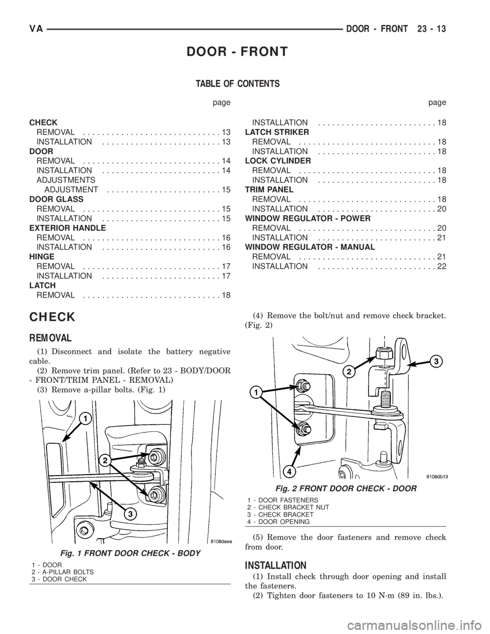
(3) Remove a-pillar bolts. (Fig. 1)(4) Remove the bolt/nut and remove check bracket.
(Fig. 2)
(5) Remove the door fasteners and remove check
from door.
INSTALLATION
(1) Install check through door opening and install
the fasteners.
(2) Tighten door fasteners to 10 N´m (89 in. lbs.).
Fig. 1 FRONT DOOR CHECK - BODY
1 - DOOR
2 - A-PILLAR BOLTS
3 - DOOR CHECK
Fig. 2 FRONT DOOR CHECK - DOOR
1 - DOOR FASTENERS
2 - CHECK BRACKET NUT
3 - CHECK BRACKET
4 - DOOR OPENING
VADOOR - FRONT 23 - 13
Page 1959 of 2305
(4) Tighten the reinforcement bolts to 21 N´m (18
ft. lbs.).
(5) Install the regulator. (Refer to 23 - BODY/
DOOR - FRONT/WINDOW REGULATOR - POWER
or MANUAL - INSTALLATION)
EXTERIOR HANDLE
REMOVAL
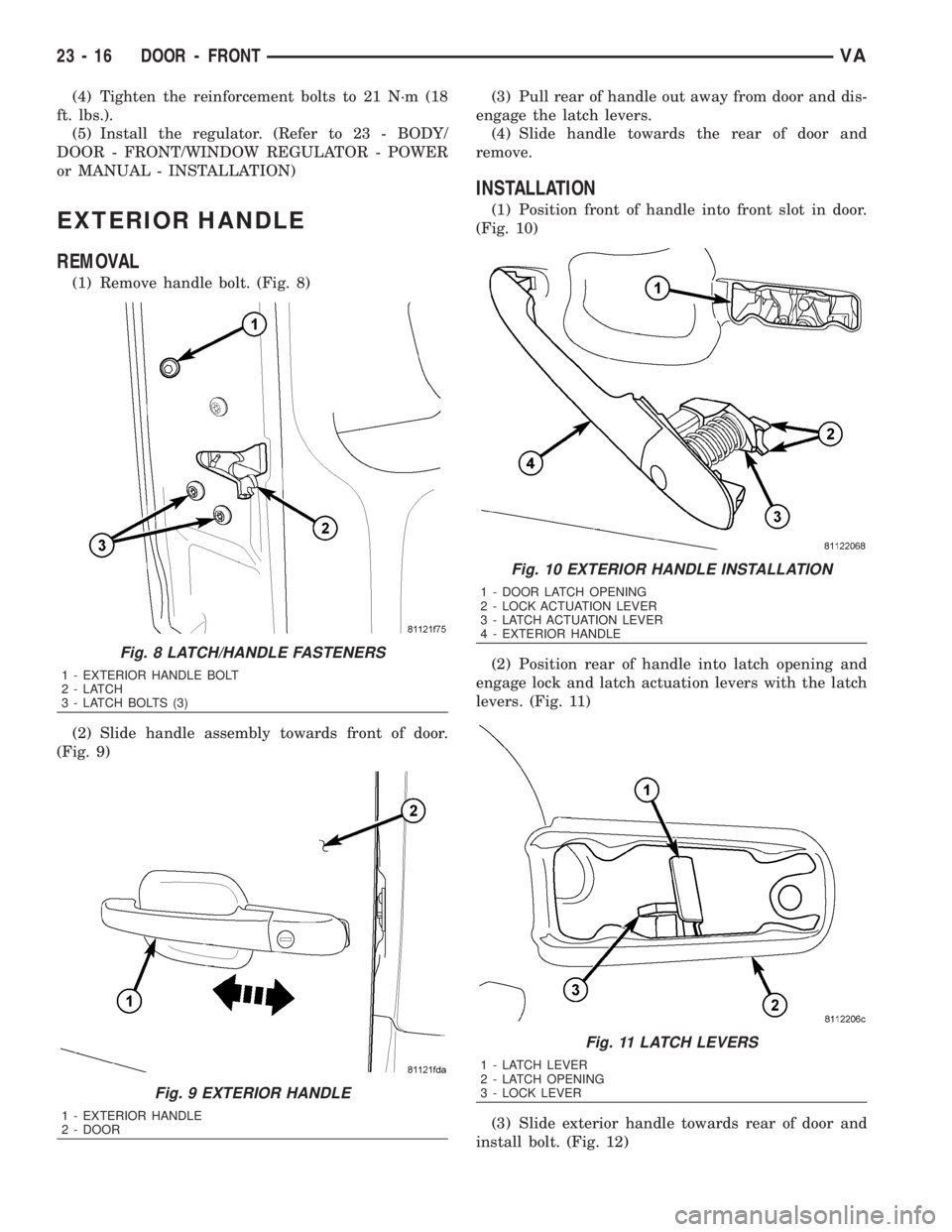
(1) Remove handle bolt. (Fig. 8)
(2) Slide handle assembly towards front of door.
(Fig. 9)(3) Pull rear of handle out away from door and dis-
engage the latch levers.
(4) Slide handle towards the rear of door and
remove.
INSTALLATION
(1) Position front of handle into front slot in door.
(Fig. 10)
(2) Position rear of handle into latch opening and
engage lock and latch actuation levers with the latch
levers. (Fig. 11)
(3) Slide exterior handle towards rear of door and
install bolt. (Fig. 12)
Fig. 8 LATCH/HANDLE FASTENERS
1 - EXTERIOR HANDLE BOLT
2-LATCH
3 - LATCH BOLTS (3)
Fig. 9 EXTERIOR HANDLE
1 - EXTERIOR HANDLE
2 - DOOR
Fig. 10 EXTERIOR HANDLE INSTALLATION
1 - DOOR LATCH OPENING
2 - LOCK ACTUATION LEVER
3 - LATCH ACTUATION LEVER
4 - EXTERIOR HANDLE
Fig. 11 LATCH LEVERS
1 - LATCH LEVER
2 - LATCH OPENING
3 - LOCK LEVER
23 - 16 DOOR - FRONTVA
Page 1961 of 2305
LATCH
REMOVAL
(1) Remove trim panel. (Refer to 23 - BODY/DOOR
- FRONT/TRIM PANEL - REMOVAL)
(2) Remove exterior handle. (Refer to 23 - BODY/
DOOR - FRONT/EXTERIOR HANDLE - REMOVAL)
(3) Remove screws and remove latch assembly.
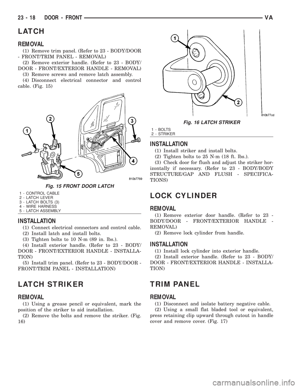
(4) Disconnect electrical connector and control
cable. (Fig. 15)
INSTALLATION
(1) Connect electrical connectors and control cable.
(2) Install latch and install bolts.
(3) Tighten bolts to 10 N´m (89 in. lbs.).
(4) Install exterior handle. (Refer to 23 - BODY/
DOOR - FRONT/EXTERIOR HANDLE - INSTALLA-
TION)
(5) Install trim panel. (Refer to 23 - BODY/DOOR -
FRONT/TRIM PANEL - INSTALLATION)
LATCH STRIKER
REMOVAL
(1) Using a grease pencil or equivalent, mark the
position of the striker to aid installation.
(2) Remove the bolts and remove the striker. (Fig.
16)
INSTALLATION
(1) Install striker and install bolts.
(2) Tighten bolts to 25 N´m (18 ft. lbs.).
(3) Check door for flush and adjust the striker hor-
izontally if necessary. (Refer to 23 - BODY/BODY
STRUCTURE/GAP AND FLUSH - SPECIFICA-
TIONS)
LOCK CYLINDER
REMOVAL
(1) Remove exterior door handle. (Refer to 23 -
BODY/DOOR - FRONT/EXTERIOR HANDLE -
REMOVAL)
(2) Remove lock cylinder from handle.
INSTALLATION
(1) Install lock cylinder into exterior handle.
(2) Install exterior handle. (Refer to 23 - BODY/
DOOR - FRONT/EXTERIOR HANDLE - INSTALLA-
TION)
TRIM PANEL
REMOVAL
(1) Disconnect and isolate battery negative cable.
(2) Using a small flat bladed tool or equivalent,
press retaining clip upward through cutout in handle
cover and remove cover. (Fig. 17)
Fig. 15 FRONT DOOR LATCH
1 - CONTROL CABLE
2 - LATCH LEVER
3 - LATCH BOLTS (3)
4 - WIRE HARNESS
5 - LATCH ASSEMBLY
Fig. 16 LATCH STRIKER
1 - BOLTS
2 - STRIKER
23 - 18 DOOR - FRONTVA
Page 1963 of 2305
(8) Slightly pull door trim upward and swing away
slightly.
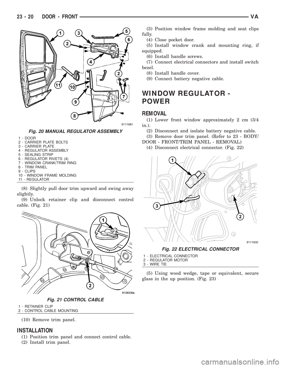
(9) Unlock retainer clip and disconnect control
cable. (Fig. 21)
(10) Remove trim panel.
INSTALLATION
(1) Position trim panel and connect control cable.
(2) Install trim panel.(3) Position window frame molding and seat clips
fully.
(4) Close pocket door.
(5) Install window crank and mounting ring, if
equipped.
(6) Install handle screws.
(7) Connect electrical connectors and install switch
bezel.
(8) Install handle cover.
(9) Connect battery negative cable.
WINDOW REGULATOR -
POWER
REMOVAL
(1) Lower front window approximately 2 cm (3/4
in.).
(2) Disconnect and isolate battery negative cable.
(3) Remove door trim panel. (Refer to 23 - BODY/
DOOR - FRONT/TRIM PANEL - REMOVAL)
(4) Disconnect electrical connector. (Fig. 22)
(5) Using wood wedge, tape or equivalent, secure
glass in the up position. (Fig. 23)
Fig. 20 MANUAL REGULATOR ASSEMBLY
1 - DOOR
2 - CARRIER PLATE BOLTS
3 - CARRIER PLATE
4 - REGULATOR ASSEMBLY
5 - SEALING STRIP
6 - REGULATOR RIVETS (4)
7 - WINDOW CRANK/TRIM RING
8 - TRIM PANEL
9 - CLIPS
10 - WINDOW FRAME MOLDING
11 - REGULATOR
Fig. 21 CONTROL CABLE
1 - RETAINER CLIP
2 - CONTROL CABLE MOUNTING
Fig. 22 ELECTRICAL CONNECTOR
1 - ELECTRICAL CONNECTOR
2 - REGULATOR MOTOR
3 - WIRE TIE
23 - 20 DOOR - FRONTVA
Page 1968 of 2305
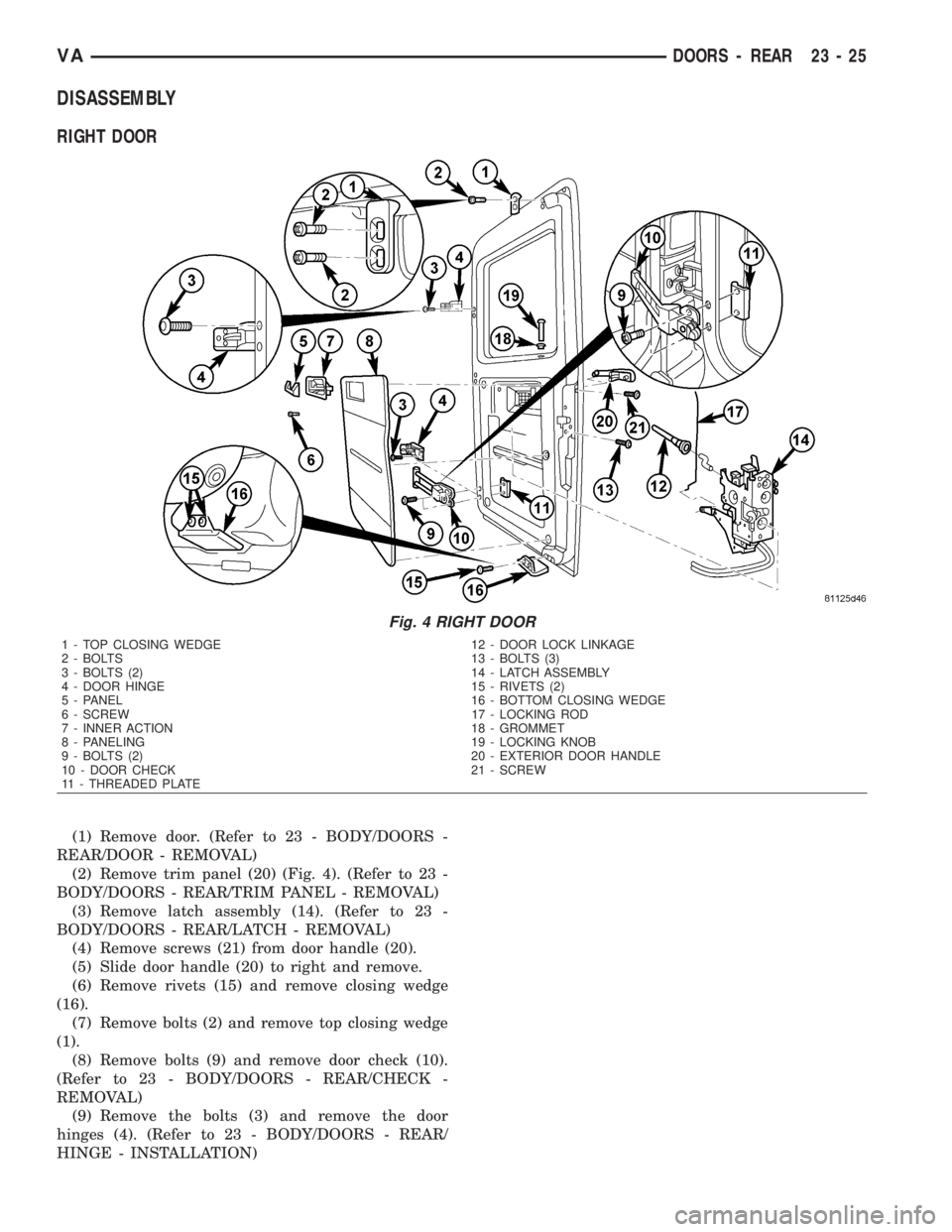
DISASSEMBLY
RIGHT DOOR
(1) Remove door. (Refer to 23 - BODY/DOORS -
REAR/DOOR - REMOVAL)
(2) Remove trim panel (20) (Fig. 4). (Refer to 23 -
BODY/DOORS - REAR/TRIM PANEL - REMOVAL)
(3) Remove latch assembly (14). (Refer to 23 -
BODY/DOORS - REAR/LATCH - REMOVAL)
(4) Remove screws (21) from door handle (20).
(5) Slide door handle (20) to right and remove.
(6) Remove rivets (15) and remove closing wedge
(16).
(7) Remove bolts (2) and remove top closing wedge
(1).
(8) Remove bolts (9) and remove door check (10).
(Refer to 23 - BODY/DOORS - REAR/CHECK -
REMOVAL)
(9) Remove the bolts (3) and remove the door
hinges (4). (Refer to 23 - BODY/DOORS - REAR/
HINGE - INSTALLATION)
Fig. 4 RIGHT DOOR
1 - TOP CLOSING WEDGE 12 - DOOR LOCK LINKAGE
2 - BOLTS 13 - BOLTS (3)
3 - BOLTS (2) 14 - LATCH ASSEMBLY
4 - DOOR HINGE 15 - RIVETS (2)
5 - PANEL 16 - BOTTOM CLOSING WEDGE
6 - SCREW 17 - LOCKING ROD
7 - INNER ACTION 18 - GROMMET
8 - PANELING 19 - LOCKING KNOB
9 - BOLTS (2) 20 - EXTERIOR DOOR HANDLE
10 - DOOR CHECK 21 - SCREW
11 - THREADED PLATE
VADOORS - REAR 23 - 25
Page 1969 of 2305
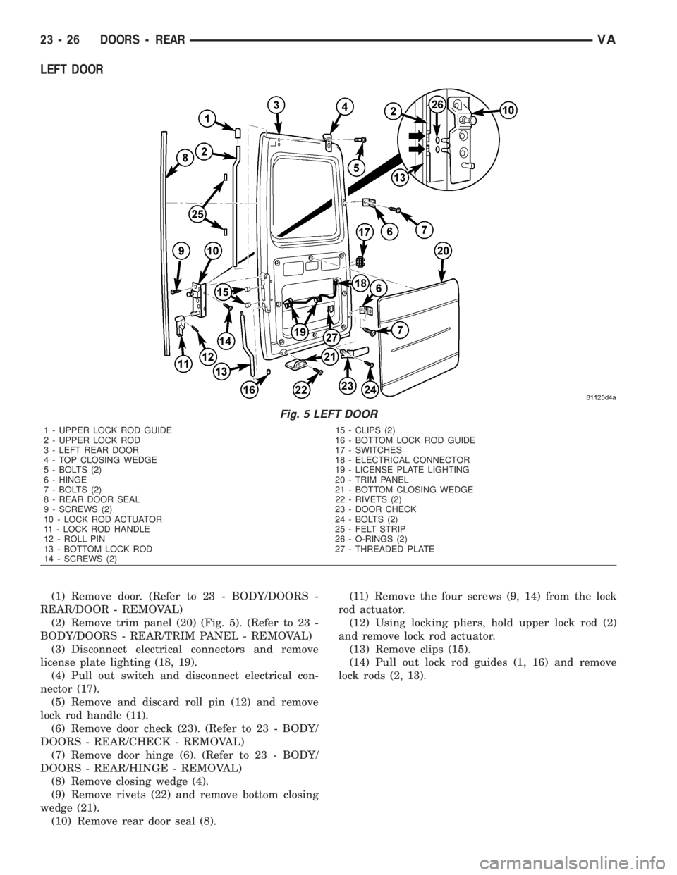
LEFT DOOR
(1) Remove door. (Refer to 23 - BODY/DOORS -
REAR/DOOR - REMOVAL)
(2) Remove trim panel (20) (Fig. 5). (Refer to 23 -
BODY/DOORS - REAR/TRIM PANEL - REMOVAL)
(3) Disconnect electrical connectors and remove
license plate lighting (18, 19).
(4) Pull out switch and disconnect electrical con-
nector (17).
(5) Remove and discard roll pin (12) and remove
lock rod handle (11).
(6) Remove door check (23). (Refer to 23 - BODY/
DOORS - REAR/CHECK - REMOVAL)
(7) Remove door hinge (6). (Refer to 23 - BODY/
DOORS - REAR/HINGE - REMOVAL)
(8) Remove closing wedge (4).
(9) Remove rivets (22) and remove bottom closing
wedge (21).
(10) Remove rear door seal (8).(11) Remove the four screws (9, 14) from the lock
rod actuator.
(12) Using locking pliers, hold upper lock rod (2)
and remove lock rod actuator.
(13) Remove clips (15).
(14) Pull out lock rod guides (1, 16) and remove
lock rods (2, 13).
Fig. 5 LEFT DOOR
1 - UPPER LOCK ROD GUIDE 15 - CLIPS (2)
2 - UPPER LOCK ROD 16 - BOTTOM LOCK ROD GUIDE
3 - LEFT REAR DOOR 17 - SWITCHES
4 - TOP CLOSING WEDGE 18 - ELECTRICAL CONNECTOR
5 - BOLTS (2) 19 - LICENSE PLATE LIGHTING
6 - HINGE 20 - TRIM PANEL
7 - BOLTS (2) 21 - BOTTOM CLOSING WEDGE
8 - REAR DOOR SEAL 22 - RIVETS (2)
9 - SCREWS (2) 23 - DOOR CHECK
10 - LOCK ROD ACTUATOR 24 - BOLTS (2)
11 - LOCK ROD HANDLE 25 - FELT STRIP
12 - ROLL PIN 26 - O-RINGS (2)
13 - BOTTOM LOCK ROD 27 - THREADED PLATE
14 - SCREWS (2)
23 - 26 DOORS - REARVA
Page 1970 of 2305
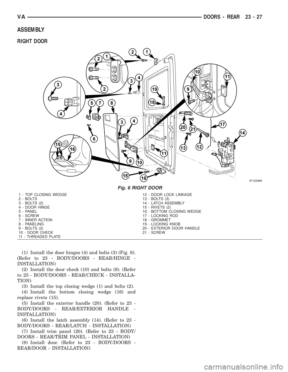
ASSEMBLY
RIGHT DOOR
(1) Install the door hinges (4) and bolts (3) (Fig. 6).
(Refer to 23 - BODY/DOORS - REAR/HINGE -
INSTALLATION)
(2) Install the door check (10) and bolts (9). (Refer
to 23 - BODY/DOORS - REAR/CHECK - INSTALLA-
TION)
(3) Install the top closing wedge (1) and bolts (2).
(4) Install the bottom closing wedge (16) and
replace rivets (15).
(5) Install the exterior handle (20). (Refer to 23 -
BODY/DOORS - REAR/EXTERIOR HANDLE -
INSTALLATION)
(6) Install the latch assembly (14). (Refer to 23 -
BODY/DOORS - REAR/LATCH - INSTALLATION)
(7) Install trim panel (20). (Refer to 23 - BODY/
DOORS - REAR/TRIM PANEL - INSTALLATION)
(8) Install door. (Refer to 23 - BODY/DOORS -
REAR/DOOR - INSTALLATION)
Fig. 6 RIGHT DOOR
1 - TOP CLOSING WEDGE 12 - DOOR LOCK LINKAGE
2 - BOLTS 13 - BOLTS (3)
3 - BOLTS (2) 14 - LATCH ASSEMBLY
4 - DOOR HINGE 15 - RIVETS (2)
5 - PANEL 16 - BOTTOM CLOSING WEDGE
6 - SCREW 17 - LOCKING ROD
7 - INNER ACTION 18 - GROMMET
8 - PANELING 19 - LOCKING KNOB
9 - BOLTS (2) 20 - EXTERIOR DOOR HANDLE
10 - DOOR CHECK 21 - SCREW
11 - THREADED PLATE
VADOORS - REAR 23 - 27