2006 MERCEDES-BENZ SPRINTER lock
[x] Cancel search: lockPage 1918 of 2305
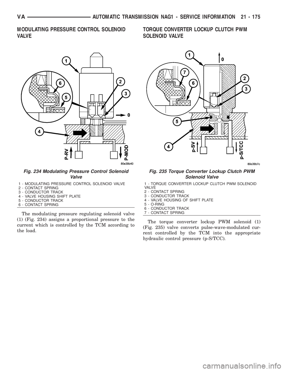
MODULATING PRESSURE CONTROL SOLENOID
VALVE
The modulating pressure regulating solenoid valve
(1) (Fig. 234) assigns a proportional pressure to the
current which is controlled by the TCM according to
the load.
TORQUE CONVERTER LOCKUP CLUTCH PWM
SOLENOID VALVE
The torque converter lockup PWM solenoid (1)
(Fig. 235) valve converts pulse-wave-modulated cur-
rent controlled by the TCM into the appropriate
hydraulic control pressure (p-S/TCC).
Fig. 234 Modulating Pressure Control Solenoid
Valve
1 - MODULATING PRESSURE CONTROL SOLENOID VALVE
2 - CONTACT SPRING
3 - CONDUCTOR TRACK
4 - VALVE HOUSING SHIFT PLATE
5 - CONDUCTOR TRACK
6 - CONTACT SPRING
Fig. 235 Torque Converter Lockup Clutch PWM
Solenoid Valve
1 - TORQUE CONVERTER LOCKUP CLUTCH PWM SOLENOID
VA LV E
2 - CONTACT SPRING
3 - CONDUCTOR TRACK
4 - VALVE HOUSING OF SHIFT PLATE
5 - O-RING
6 - CONDUCTOR TRACK
7 - CONTACT SPRING
VAAUTOMATIC TRANSMISSION NAG1 - SERVICE INFORMATION 21 - 175
Page 1924 of 2305
STATOR
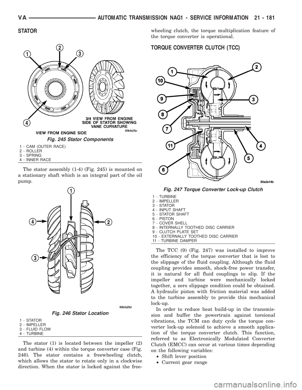
The stator assembly (1-4) (Fig. 245) is mounted on
a stationary shaft which is an integral part of the oil
pump.
The stator (1) is located between the impeller (2)
and turbine (4) within the torque converter case (Fig.
246). The stator contains a freewheeling clutch,
which allows the stator to rotate only in a clockwise
direction. When the stator is locked against the free-wheeling clutch, the torque multiplication feature of
the torque converter is operational.
TORQUE CONVERTER CLUTCH (TCC)
The TCC (9) (Fig. 247) was installed to improve
the efficiency of the torque converter that is lost to
the slippage of the fluid coupling. Although the fluid
coupling provides smooth, shock-free power transfer,
it is natural for all fluid couplings to slip. If the
impeller and turbine were mechanically locked
together, a zero slippage condition could be obtained.
A hydraulic piston with friction material was added
to the turbine assembly to provide this mechanical
lock-up.
In order to reduce heat build-up in the transmis-
sion and buffer the powertrain against torsional
vibrations, the TCM can duty cycle the torque con-
verter lock-up solenoid to achieve a smooth applica-
tion of the torque converter clutch. This function,
referred to as Electronically Modulated Converter
Clutch (EMCC) can occur at various times depending
on the following variables:
²Shift lever position
²Current gear range
Fig. 245 Stator Components
1 - CAM (OUTER RACE)
2 - ROLLER
3 - SPRING
4 - INNER RACE
Fig. 246 Stator Location
1-STATOR
2 - IMPELLER
3 - FLUID FLOW
4 - TURBINE
Fig. 247 Torque Converter Lock-up Clutch
1 - TURBINE
2 - IMPELLER
3-STATOR
4 - INPUT SHAFT
5 - STATOR SHAFT
6 - PISTON
7 - COVER SHELL
8 - INTERNALLY TOOTHED DISC CARRIER
9 - CLUTCH PLATE SET
10 - EXTERNALLY TOOTHED DISC CARRIER
11 - TURBINE DAMPER
VAAUTOMATIC TRANSMISSION NAG1 - SERVICE INFORMATION 21 - 181
Page 1925 of 2305
²Transmission fluid temperature
²Engine coolant temperature
²Input speed
²Throttle angle
²Engine speed
OPERATION
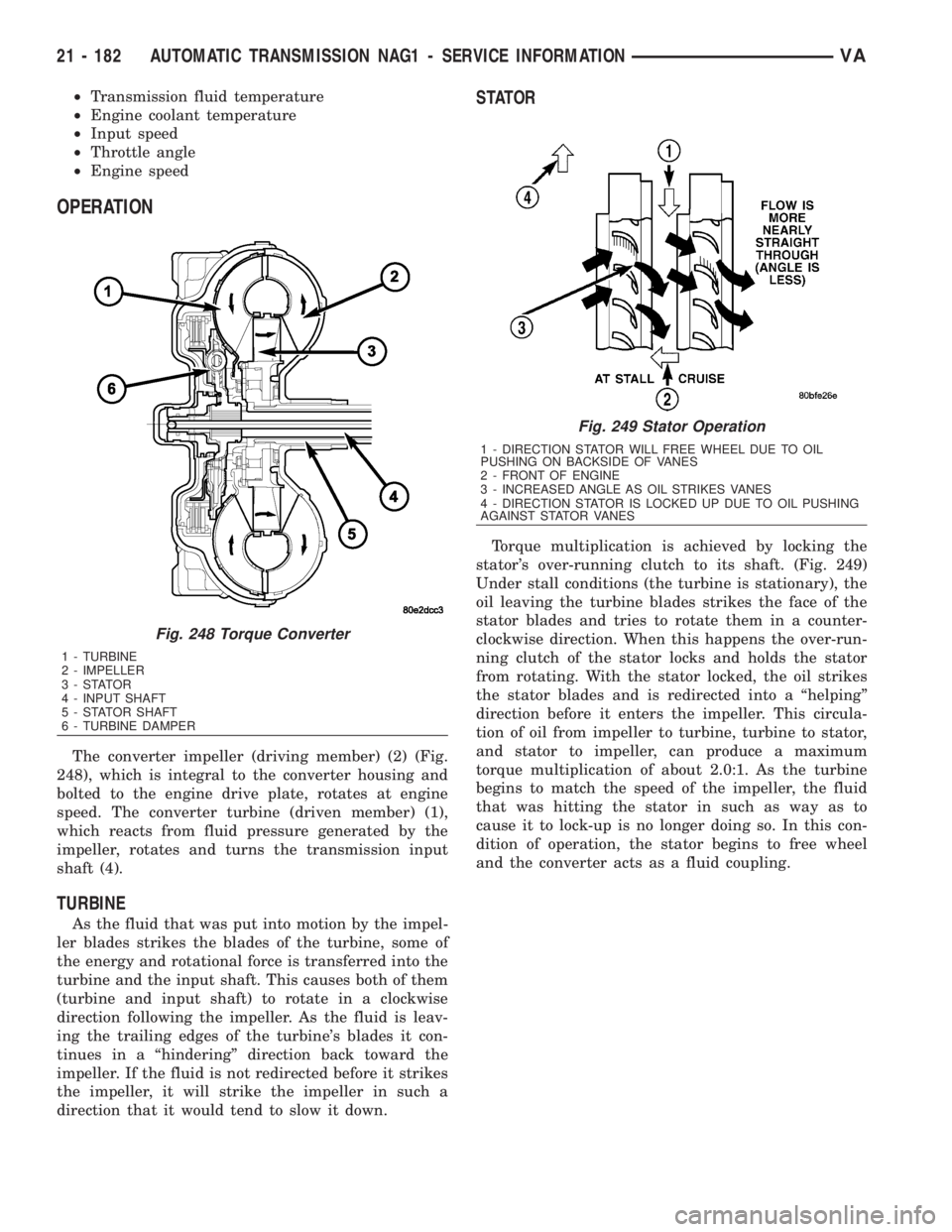
The converter impeller (driving member) (2) (Fig.
248), which is integral to the converter housing and
bolted to the engine drive plate, rotates at engine
speed. The converter turbine (driven member) (1),
which reacts from fluid pressure generated by the
impeller, rotates and turns the transmission input
shaft (4).
TURBINE
As the fluid that was put into motion by the impel-
ler blades strikes the blades of the turbine, some of
the energy and rotational force is transferred into the
turbine and the input shaft. This causes both of them
(turbine and input shaft) to rotate in a clockwise
direction following the impeller. As the fluid is leav-
ing the trailing edges of the turbine's blades it con-
tinues in a ªhinderingº direction back toward the
impeller. If the fluid is not redirected before it strikes
the impeller, it will strike the impeller in such a
direction that it would tend to slow it down.
STATOR
Torque multiplication is achieved by locking the
stator's over-running clutch to its shaft. (Fig. 249)
Under stall conditions (the turbine is stationary), the
oil leaving the turbine blades strikes the face of the
stator blades and tries to rotate them in a counter-
clockwise direction. When this happens the over-run-
ning clutch of the stator locks and holds the stator
from rotating. With the stator locked, the oil strikes
the stator blades and is redirected into a ªhelpingº
direction before it enters the impeller. This circula-
tion of oil from impeller to turbine, turbine to stator,
and stator to impeller, can produce a maximum
torque multiplication of about 2.0:1. As the turbine
begins to match the speed of the impeller, the fluid
that was hitting the stator in such as way as to
cause it to lock-up is no longer doing so. In this con-
dition of operation, the stator begins to free wheel
and the converter acts as a fluid coupling.
Fig. 248 Torque Converter
1 - TURBINE
2 - IMPELLER
3-STATOR
4 - INPUT SHAFT
5 - STATOR SHAFT
6 - TURBINE DAMPER
Fig. 249 Stator Operation
1 - DIRECTION STATOR WILL FREE WHEEL DUE TO OIL
PUSHING ON BACKSIDE OF VANES
2 - FRONT OF ENGINE
3 - INCREASED ANGLE AS OIL STRIKES VANES
4 - DIRECTION STATOR IS LOCKED UP DUE TO OIL PUSHING
AGAINST STATOR VANES
21 - 182 AUTOMATIC TRANSMISSION NAG1 - SERVICE INFORMATIONVA
Page 1926 of 2305
TORQUE CONVERTER CLUTCH (TCC)
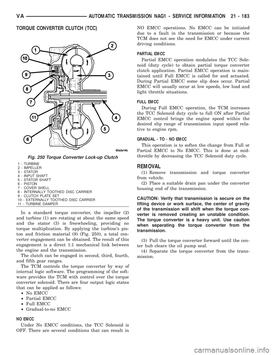
In a standard torque converter, the impeller (2)
and turbine (1) are rotating at about the same speed
and the stator (3) is freewheeling, providing no
torque multiplication. By applying the turbine's pis-
ton and friction material (9) (Fig. 250), a total con-
verter engagement can be obtained. The result of this
engagement is a direct 1:1 mechanical link between
the engine and the transmission.
The clutch can be engaged in second, third, fourth,
and fifth gear ranges.
The TCM controls the torque converter by way of
internal logic software. The programming of the soft-
ware provides the TCM with control over the torque
converter solenoid. There are four output logic states
that can be applied as follows:
²No EMCC
²Partial EMCC
²Full EMCC
²Gradual-to-no EMCC
NO EMCC
Under No EMCC conditions, the TCC Solenoid is
OFF. There are several conditions that can result inNO EMCC operations. No EMCC can be initiated
due to a fault in the transmission or because the
TCM does not see the need for EMCC under current
driving conditions.
PARTIAL EMCC
Partial EMCC operation modulates the TCC Sole-
noid (duty cycle) to obtain partial torque converter
clutch application. Partial EMCC operation is main-
tained until Full EMCC is called for and actuated.
During Partial EMCC some slip does occur. Partial
EMCC will usually occur at low speeds, low load and
light throttle situations.
FULL EMCC
During Full EMCC operation, the TCM increases
the TCC Solenoid duty cycle to full ON after Partial
EMCC control brings the engine speed within the
desired slip range of transmission input speed rela-
tive to engine rpm.
GRADUAL - TO - NO EMCC
This operation is to soften the change from Full or
Partial EMCC to No EMCC. This is done at mid-
throttle by decreasing the TCC Solenoid duty cycle.
REMOVAL
(1) Remove transmission and torque converter
from vehicle.
(2) Place a suitable drain pan under the converter
housing end of the transmission.
CAUTION: Verify that transmission is secure on the
lifting device or work surface, the center of gravity
of the transmission will shift when the torque con-
verter is removed creating an unstable condition.
The torque converter is a heavy unit. Use caution
when separating the torque converter from the
transmission.
(3) Pull the torque converter forward until the cen-
ter hub clears the oil pump seal.
(4) Separate the torque converter from the trans-
mission.
Fig. 250 Torque Converter Lock-up Clutch
1 - TURBINE
2 - IMPELLER
3-STATOR
4 - INPUT SHAFT
5 - STATOR SHAFT
6 - PISTON
7 - COVER SHELL
8 - INTERNALLY TOOTHED DISC CARRIER
9 - CLUTCH PLATE SET
10 - EXTERNALLY TOOTHED DISC CARRIER
11 - TURBINE DAMPER
VAAUTOMATIC TRANSMISSION NAG1 - SERVICE INFORMATION 21 - 183
Page 1935 of 2305
Radial-ply tires must always be used in sets of
four. Under no circumstances should they be used on
the front only. They may be mixed with temporary
spare tires when necessary. A maximum speed of 50
MPH is recommended while a temporary spare is in
use.
Radial-ply tires have the same load-carrying capac-
ity as other types of tires of the same size. They also
use the same recommended inflation pressures.
The use of oversized tires, either in the front or
rear of the vehicle, can cause vehicle drive train fail-
ure. This could also cause inaccurate wheel speed
signals when the vehicle is equipped with Anti-Lock
Brakes.
The use of tires from different manufactures on the
same vehicle is NOT recommended. The proper tire
pressure should be maintained on all four tires.
DESCRIPTION - TIRE PRESSURE FOR HIGH
SPEEDS
Where speed limits allow the vehicle to be driven
at high speeds, correct tire inflation pressure is very
important. For speeds up to and including 120 km/h
(75 mph), tires must be inflated to the pressures
shown on the tire placard. For continuous speeds in
excess of 120 km/h (75 mph), tires must be inflated
to the maximum pressure specified on the tire side-
wall.
Vehicles loaded to the maximum capacity should
not be driven at continuous speeds above 75 mph
(120 km/h).
For emergency vehicles that are driven at speeds
over 90 mph (144 km/h), special high speed tires
must be used. Consult tire manufacturer for correct
inflation pressure recommendations.
DESCRIPTION - REPLACEMENT TIRES
The original equipment tires provide a proper bal-
ance of many characteristics such as:
²Ride
²Noise
²Handling
²Durability
²Tread life
²Traction
²Rolling resistance
²Speed capability
It is recommended that tires equivalent to the orig-
inal equipment tires be used when replacement is
needed.
Failure to use equivalent replacement tires may
adversely affect the safety and handling of the vehi-
cle.The use of oversize tires may cause interference
with vehicle components. Under extremes of suspen-
sion and steering travel, interference with vehicle
components may cause tire damage.
WARNING: FAILURE TO EQUIP THE VEHICLE WITH
TIRES HAVING ADEQUATE SPEED CAPABILITY
CAN RESULT IN SUDDEN TIRE FAILURE.
DESCRIPTION - TIRE INFLATION PRESSURES
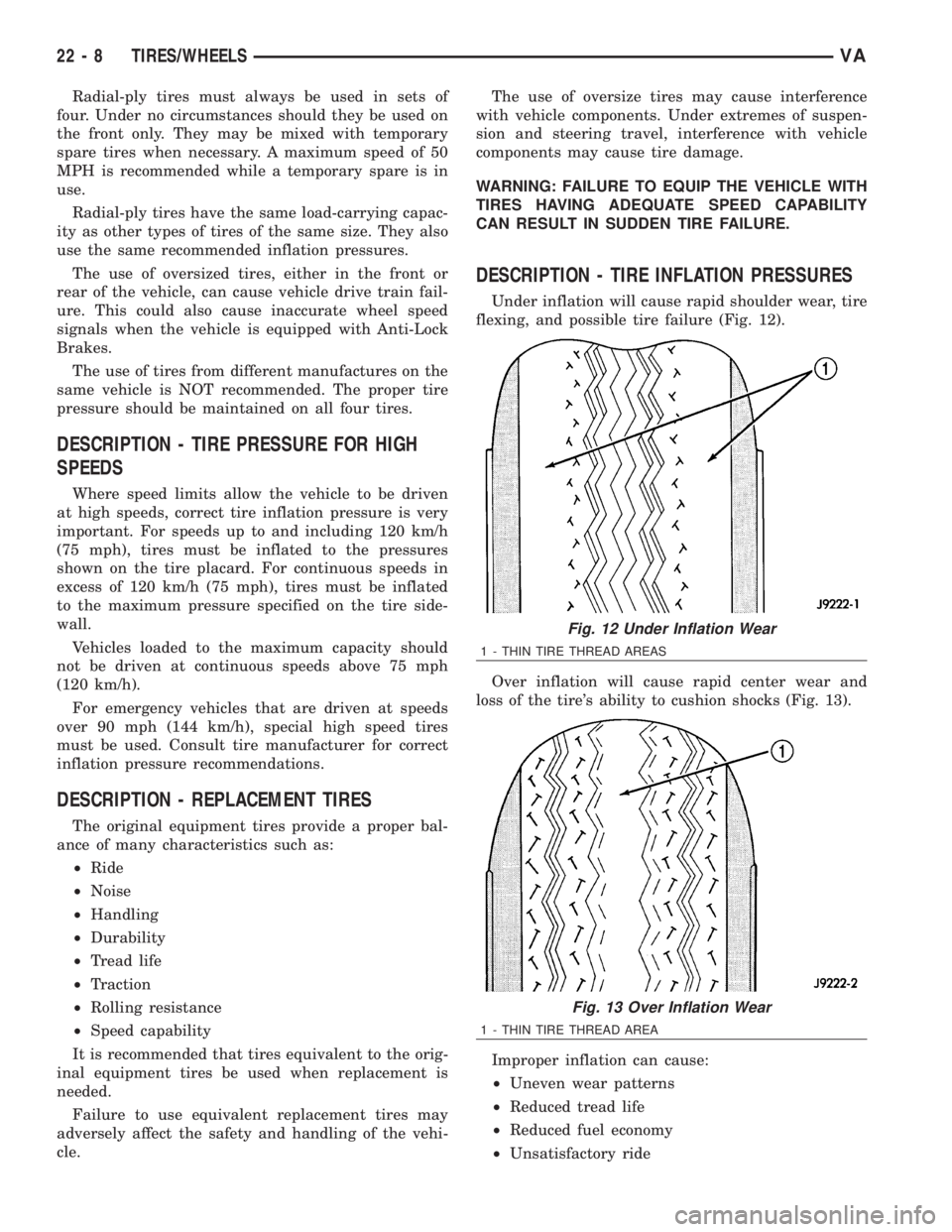
Under inflation will cause rapid shoulder wear, tire
flexing, and possible tire failure (Fig. 12).
Over inflation will cause rapid center wear and
loss of the tire's ability to cushion shocks (Fig. 13).
Improper inflation can cause:
²Uneven wear patterns
²Reduced tread life
²Reduced fuel economy
²Unsatisfactory ride
Fig. 12 Under Inflation Wear
1 - THIN TIRE THREAD AREAS
Fig. 13 Over Inflation Wear
1 - THIN TIRE THREAD AREA
22 - 8 TIRES/WHEELSVA
Page 1944 of 2305
BODY
TABLE OF CONTENTS
page page
BODY
WARNING
SAFETY PRECAUTIONS AND WARNINGS . . . 1
DIAGNOSIS AND TESTING
DIAGNOSIS AND TESTING - WATER LEAKS . 1
DIAGNOSIS AND TESTING - WIND NOISE . . . 2
STANDARD PROCEDURE
STANDARD PROCEDURE - PLASTIC BODY
PANEL REPAIR........................3
STANDARD PROCEDURE - BUZZ, SQUEAK
& RATTLE...........................10
SPECIFICATIONS.......................11DOOR - FRONT..........................13
DOORS - REAR..........................23
DOORS - SLIDING........................35
EXTERIOR..............................48
HOOD.................................51
INSTRUMENT PANEL.....................55
INTERIOR..............................70
PAINT.................................77
SEATS.................................79
STATIONARY GLASS.....................84
WEATHERSTRIP/SEALS...................90
BODY STRUCTURE.......................91
BODY
WARNING
SAFETY PRECAUTIONS AND WARNINGS
WARNING: USE AN OSHA APPROVED BREATHING
FILTER WHEN SPRAYING PAINT OR SOLVENTS IN
A CONFINED AREA. PERSONAL INJURY CAN
RESULT.
²AVOID PROLONGED SKIN CONTACT WITH
PETROLEUM OR ALCOHOL ± BASED CLEANING
SOLVENTS. PERSONAL INJURY CAN RESULT.
²DO NOT STAND UNDER A HOISTED VEHICLE
THAT IS NOT PROPERLY SUPPORTED ON SAFETY
STANDS. PERSONAL INJURY CAN RESULT.
CAUTION: When holes must be drilled or punched
in an inner body panel, verify depth of space to the
outer body panel, electrical wiring, or other compo-
nents. Damage to vehicle can result.
²Do not weld exterior panels unless combustible
material on the interior of vehicle is removed from
the repair area. Fire or hazardous conditions, can
result.
²Always have a fire extinguisher ready for use
when welding.
²Disconnect the negative (-) cable clamp from
the battery when servicing electrical components
that are live when the ignition is OFF. Damage to
electrical system can result.
²Do not use abrasive chemicals or compounds
on painted surfaces. Damage to finish can result.²Do not use harsh alkaline based cleaning sol-
vents on painted or upholstered surfaces. Damage
to finish or color can result.
²Do not hammer or pound on plastic trim panel
when servicing interior trim. Plastic panels can
break.DIAGNOSIS AND TESTING
DIAGNOSIS AND TESTING - WATER LEAKS
Water leaks can be caused by poor sealing,
improper body component alignment, body seam
porosity, missing plugs, or blocked drain holes. Cen-
trifugal and gravitational force can cause water to
drip from a location away from the actual leak point,
making leak detection difficult. All body sealing
points should be water tight in normal wet-driving
conditions. Water flowing downward from the front of
the vehicle should not enter the passenger or luggage
compartment. Moving sealing surfaces will not
always seal water tight under all conditions. At
times, side glass or door seals will allow water to
enter the passenger compartment during high pres-
sure washing or hard driving rain (severe) condi-
tions. Overcompensating on door or glass
adjustments to stop a water leak that occurs under
severe conditions can cause premature seal wear and
excessive closing or latching effort. After completing
a repair, water test vehicle to verify leak has stopped
before returning vehicle to use.
VISUAL INSPECTION BEFORE WATER LEAK TESTS
Verify that floor and body plugs are in place, body
drains are clear, and body components are properly
VABODY 23 - 1
Page 1947 of 2305
CODE FAMILY NAME COMMON TRADE NAME TYPICAL APPLICATION
ABS/PVC ABS/PV ALLOY PROLOY, PULSE, LUSTRAN,
CYCLOVINDOOR PANELS, GRILLES,
TRIM
BMC BULK MOLDING COM-
POUNDBMC FENDER EXTENSIONS
EMA EHTYLENE METHYL ACRY-
LATE/IONOMERSURLYN, EMA, IONOMER BUMPER GUARDS, PADS
METTON METTON METTON GRILLES, KICK PANELS,
RUNNING BOARDS
MPPO MODIFIED POLYPHE-
NYLENE OXIDEMPPO SPOILER ASSEMBLY
PA POLYAMID ZYTEL, VYDYNE, PA, MIN-
LONFENDERS, QUARTER PAN-
ELS
PET THERMOPLASTIC POLYES-
TERRYNITE TRIM
PBT/PPO PBT/PPO ALLOY GERMAX CLADDINGS
PBTP POLYBUTYLENE
THEREPTHALATEPBT, PBTP, POCAN, VALOX WHEEL COVERS, FENDERS,
GRILLES
PBTP/EEBC POLYBUTYLENE
THEREPTHALATE/EEBC
ALLOYBEXLOY, ªMº, PBTP/EEBC FASCIAS, ROCKER PANEL,
MOLDINGS
PC POLYCARBONATE LEXAN, MERLON, CALIBRE,
MAKROLON PCTAIL LIGHT LENSES, IP
TRIM, VALANCE PANELS
PC/ABS PC/ABS ALLOY GERMAX, BAY BLENDS,
PULSEDOORS, INSTRUMENT PAN-
ELS
PPO POLYPHENYLENE OXIDE AZDEL, HOSTALEN, MAR-
LEX, PRFAX, NORYL, GTX,
PPOINTERIOR TRIM, DOOR PAN-
ELS, SPLASH SHIELDS,
STEERING COLUMN
SHROUD
PPO/PA POLYPHENYLENE/POLYA-
MIDPPO/PA, GTX 910 FENDERS, QUARTER PAN-
ELS
PR/FV FIBERGLASS REINFORCED
PLASTICFIBERGLASS, FV, PR/FV BODY PANELS
PS POLYSTYRENE LUSTREX, STYRON, PS DOOR PANELS, DASH PAN-
ELS
RTM RESIN TRANSFER MOLD-
ING COMPOUNDRTM BODY PANELS
SMC SHEET MOLDED COM-
POUNDSMC BODY PANELS
TMC TRANSFER MOLDING
COMPOUNDTMC GRILLES
UP UNSATURATED POLYES-
TER (THERMOSETTING)SMC, BMC, TMC, ZMC, IMC,
XSMC, UPGRILLE OPENING PANEL,
LIFTGATES, FLARESIDE
FENDERS, FENDER EXTEN-
SIONS
EEBC ETHER/ESTER BLOCKED
CO-POLYMEREEBC BUMPERS
EEBC/PBTP EEBC/POLYBUTYLENE
TEREPTHALATEEEBC, PBTP, BEXLOY BUMPER, ROCKER PANELS
23 - 4 BODYVA
Page 1953 of 2305
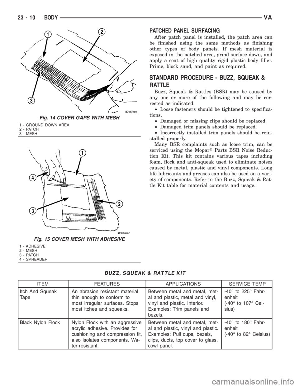
PATCHED PANEL SURFACING
After patch panel is installed, the patch area can
be finished using the same methods as finishing
other types of body panels. If mesh material is
exposed in the patched area, grind surface down, and
apply a coat of high quality rigid plastic body filler.
Prime, block sand, and paint as required.
STANDARD PROCEDURE - BUZZ, SQUEAK &
RATTLE
Buzz, Squeak & Rattles (BSR) may be caused by
any one or more of the following and may be cor-
rected as indicated:
²Loose fasteners should be tightened to specifica-
tions.
²Damaged or missing clips should be replaced.
²Damaged trim panels should be replaced.
²Incorrectly installed trim panels should be rein-
stalled properly.
Many BSR complaints such as loose trim, can be
serviced using the MopartParts BSR Noise Reduc-
tion Kit. This kit contains various tapes including
foam, flock and anti-squeak used to eliminate noises
caused by metal, plastic and vinyl components. Long
life lubricants and greases can also be used on a vari-
ety of components. Refer to the Buzz, Squeak & Rat-
tle Kit table for material contents and usage.
BUZZ, SQUEAK & RATTLE KIT
ITEM FEATURES APPLICATIONS SERVICE TEMP
Itch And Squeak
TapeAn abrasion resistant material
thin enough to conform to
most irregular surfaces. Stops
most itches and squeaks.Between metal and metal, met-
al and plastic, metal and vinyl,
vinyl and plastic. Interior.
Examples: Trim panels and
bezels.-40É to 225É Fahr-
enheit
(-40É to 107É Cel-
sius)
Black Nylon Flock Nylon Flock with an aggressive
acrylic adhesive. Provides for
cushioning and compression fit,
also isolates components. Wa-
ter-resistant.Between metal and metal, met-
al and plastic, vinyl and plastic.
Examples: Pull cups, bezels,
clips, ducts, top cover to glass,
cowl panel.-40É to 180É Fahr-
enheit
(-40É to 82É Celsius)
Fig. 14 COVER GAPS WITH MESH
1 - GROUND DOWN AREA
2 - PATCH
3 - MESH
Fig. 15 COVER MESH WITH ADHESIVE
1 - ADHESIVE
2 - MESH
3 - PATCH
4 - SPREADER
23 - 10 BODYVA