2006 LAND ROVER FRELANDER 2 relay
[x] Cancel search: relayPage 2354 of 3229
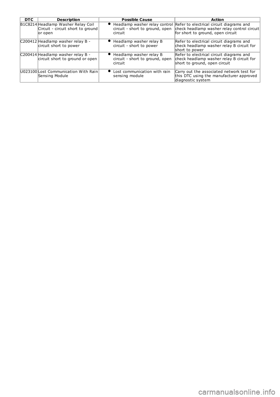
DT C
Description Possible Cause Action
B1C8214 Headlamp W as her Rel ay Coi l
Ci rcuit - circui t s hort t o ground
or open Headlamp was her relay control
circui t - short to ground, open
circui t Refer to el ect ri cal circui t diagrams and
check headl amp was her relay cont rol circui t
for s hort to ground, open circui t
C200412 Headlamp washer rel ay B -
ci rcuit s hort t o power Headlamp was her relay B
circui t - short to power Refer to el ect ri cal circui t diagrams and
check headl amp was her relay B ci rcuit for
short to power
C200414 Headlamp washer rel ay B -
ci rcuit s hort t o ground or open Headlamp was her relay B
circui t - short to ground, open
circui t Refer to el ect ri cal circui t diagrams and
check headl amp was her relay B ci rcuit for
short to ground, open circuit
U023100 Los t Communicati on W i th Rai n
Sens ing Module Lost communi cat ion wi th rain
s ens i ng module Carry out t he as sociat ed network tes t for
this DTC usi ng t he manufacturer approved
di agnos ti c s yst em
Page 2371 of 3229
Publis hed: 11-May-2011
Roof Opening Panel - Roof Opening PanelDia gnosis and Test ing
Principles of Operation
For a det ailed description of t he roof opening panel syst em, refer to t he relevant Description and Operat ion section in t he workshop ma nual.REFER t o: Roof Opening Panel (501-17 Roof Opening P anel, Des cript ion and Operation).
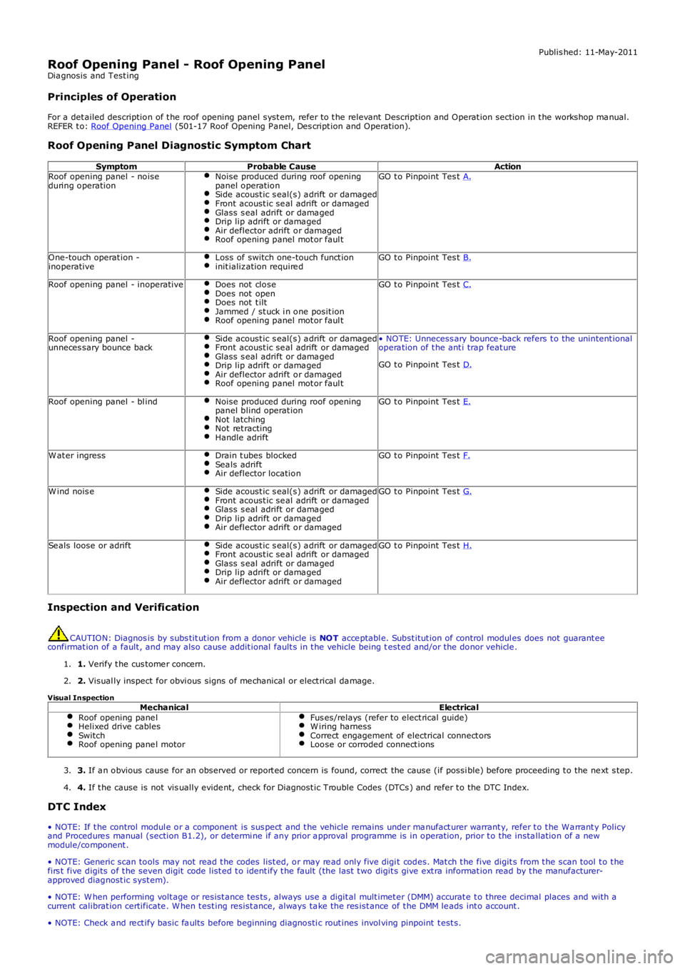
Roof Opening Panel Diagnostic Symptom Chart
SymptomProbable CauseActionRoof opening panel - noiseduring operationNoise produced during roof openingpanel operationSide acoust ic s eal(s) a drift or damagedFront acoust ic se al adrift or damagedGlass s eal adrift or dama gedDrip lip adrift or dama gedAir deflector adrift or damagedRoof opening panel mot or faul t
GO t o Pinpoint Tes t A.
One-touch operat ion -inoperativeLoss of switch one-touch funct ioninit ializ ation require dGO t o Pinpoint Tes t B.
Roof opening panel - inoperativeDoes not closeDoes not openDoes not t iltJammed / st uck i n one posit ionRoof opening panel mot or faul t
GO t o Pinpoint Tes t C.
Roof opening panel -unneces sary bounce backSide acoust ic s eal(s) a drift or damagedFront acoust ic se al adrift or damagedGlass s eal adrift or dama gedDrip lip adrift or dama gedAir deflector adrift or damagedRoof opening panel mot or faul t
• NOTE: Unnecess ary bounce -back refers t o the unintent ionalopera tion of t he ant i trap feat ure
GO t o Pinpoint Tes t D.
Roof opening panel - bl indNoise produced during roof openingpanel blind operat ionNot latchingNot ret ractingHandle adrift
GO t o Pinpoint Tes t E.
W at er ingressDrain t ubes blockedSea ls adriftAir deflector location
GO t o Pinpoint Tes t F.
W ind nois eSide acoust ic s eal(s) a drift or damagedFront acoust ic se al adrift or damagedGlass s eal adrift or dama gedDrip lip adrift or dama gedAir deflector adrift or damaged
GO t o Pinpoint Tes t G.
Se als loose or adriftSide acoust ic s eal(s) a drift or damagedFront acoust ic se al adrift or damagedGlass s eal adrift or dama gedDrip lip adrift or dama gedAir deflector adrift or damaged
GO t o Pinpoint Tes t H.
Inspection and Verification
CAUTION: Diagnos is by subs tit ut ion from a donor vehicle is NOT acce ptabl e. Subst itut ion of control modul es does not guarant eeconfirmat ion of a fault , and may also cause addit ional fault s in t he vehicle being test ed and/or the donor vehicle .
1. Verify t he cus tome r concern.1.
2. Visual ly inspect for obvi ous signs of me chanical or elect rical da mage.2.
Visual InspectionMechanicalElectricalRoof opening pane lHelixed drive cablesSwitchRoof opening pane l motor
Fus es/relays (refer to elect rical guide)W iring harnessCorrect engagement of electrical connect orsLoose or corroded connect ions
3. If a n obvious cause for an observed or report ed concern is found, correct the cause (if possi ble) before proceeding t o the ne xt s tep.3.
4. If t he cause is not vis ually evide nt, check for Diagnost ic Trouble Codes (DTCs ) and refer t o the DTC Index.4.
DTC Index
• NOTE: If t he control modul e or a component is sus pect and t he vehicle remains under ma nufact urer warrant y, refer t o t he Wa rrant y Policyand Procedure s manual (section B1.2), or determi ne if any prior a pproval programme is in operation, prior t o the insta llation of a newmodule/component .
• NOTE: Generic scan tools may not read t he codes list ed, or may re ad only five digit codes. Mat ch t he five digit s from t he scan tool t o t hefirs t five digits of t he seven digit code list ed t o ident ify t he fault (the last t wo digit s give ext ra informat ion read by t he manufacturer-approved diagnost ic syst em).
• NOTE: W hen performing volt age or resist ance tes ts , always use a digit al mult imet er (DMM) accurat e t o three decimal places and with acurrent calibrat ion certificate . W hen t est ing resist ance, always ta ke the res ist ance of t he DMM le ads int o account .
• NOTE: Check a nd re ct ify basic fa ults before beginning diagnosti c rout ines invol ving pinpoint t est s.
Page 2915 of 3229
195
Fuses
R
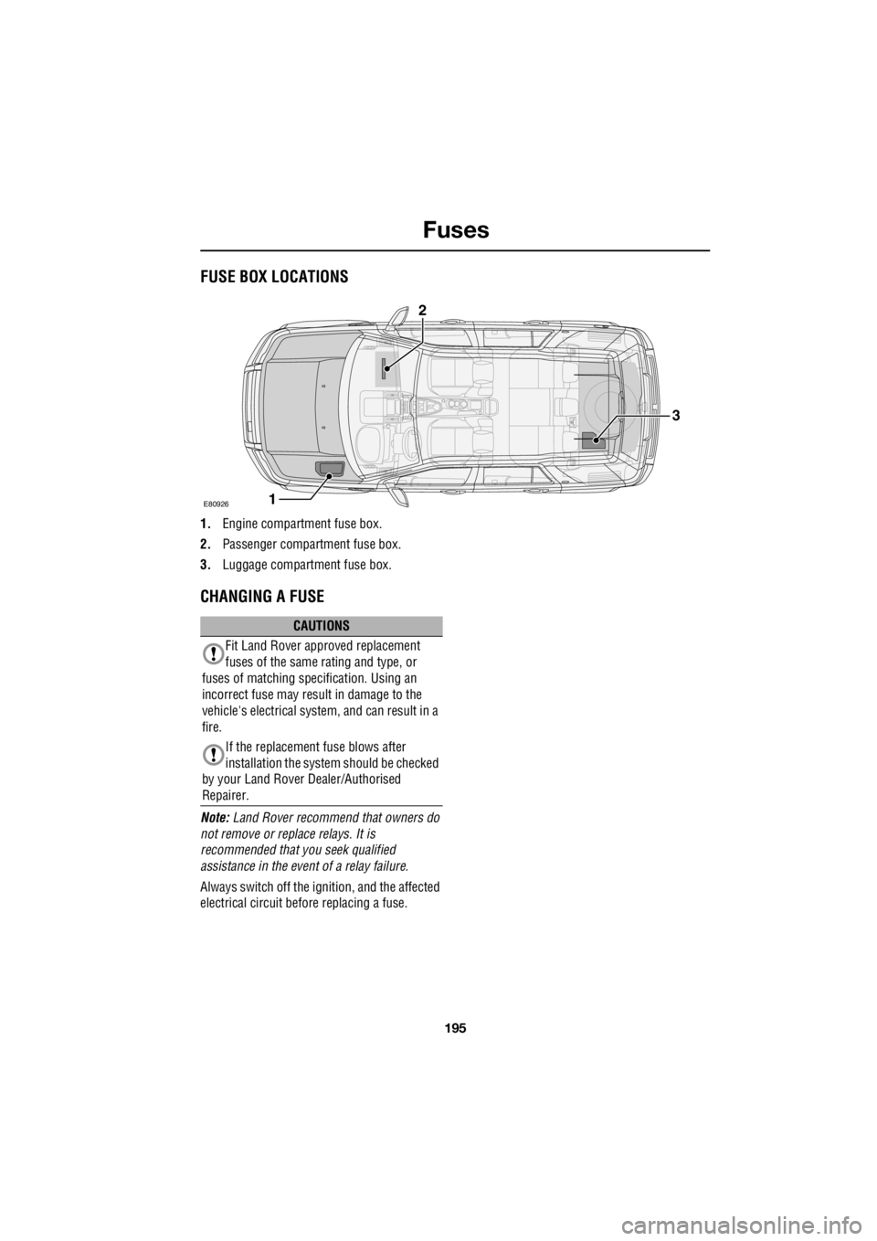
FusesFUSE BOX LOCATIONS
1. Engine compartment fuse box.
2. Passenger compartment fuse box.
3. Luggage compartment fuse box.
CHANGING A FUSE
Note: Land Rover recommend that owners do
not remove or repl ace relays. It is
recommended that you seek qualified
assistance in the event of a relay failure.
Always switch off the i gnition, and the affected
electrical circuit before replacing a fuse.
E80926
3
1
2
CAUTIONS
Fit Land Rover approved replacement
fuses of the same rating and type, or
fuses of matching spec ification. Using an
incorrect fuse may result in damage to the
vehicle's electrical system, and can result in a
fire.
If the replacement fuse blows after
installation the syst em should be checked
by your Land Rover Dealer/Authorised
Repairer.
Page 2917 of 3229

197
Fuses
R
Fuse number Rating (Amps) Fuse colour Circuits protected F1 5 tan Glow plugs
F2 15 blue Automatic transmission
F3 80 - Cooling fans
F4 60 - Glow plugs
F5 - - -
F6 (Diesel) 10 red Engine management F6 (Petrol) 15 blue Engine management F7 5 tan Relays
F8 (Diesel) 10 red Engine management F8 (Petrol) 15 blue Engine management
F9 (Diesel) 10 red Engine management
F9 (Petrol) 15 blue Engine management
F10 (Petrol) 10 red Engine management
F11 (Diesel) 10 red Engine management
F11 (Petrol) 10 red Engine management
F12 (Diesel) 10 red Engine management
F12 (Petrol) 20 yell ow Engine management
F13 15 blue Air Conditioning
F14 (Diesel) 15 blue Engine management
F15 40 green Starter motor
F16 (Diesel) 100 - Diesel PTC heater F17 60 - Passenger compartment fuse box supply
F18 60 - Passenger compartment fuse box supply
F19 60 - Luggage compartment fuse box supply
F20 60 - Luggage compartment fuse box supply
F21 60 - Luggage compartment fuse box supply - Audio unit
F22 30 pink Windscreen wipers
F23 - - -
Page 2918 of 3229

Fuses
198
L
F24 30 pink Headlamp washers
F25 30 pink ABS
F26 40 green ABS
F27 - - -
F28 40 green Heater blower
F29 - - -
F30 - - -
F31 15 blue Horns
F32 20 yellow Diesel auxiliary heater
F33 5 tan Relays
F34 40 green Heated windscreen(LH)
F35 40 green Heated windscreen (RH)
F36 - - -
F37 10 red Heated washer jets
F38 10 red AFS (RH lamp motors)
F39 10 red Climate control
F40 - - -
F41 20 yellow Passenger compartment fuse box supply
F42 15 blue Engine management
F43 5 tan Headlamp levelling control - AFS
F44 10 red AFS (LH lamp motors)
F45 15 blue Cigar lighter
Fuse number Rating (Amps) Fuse colour Circuits protected
Page 2999 of 3229
204-04 WHEELS AND TIRES
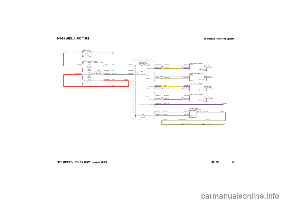
Tire pressure monitoring system
FREELANDER 2 - LR2 - VIN: 000201 onwards (LHD)(01 / 01) 11
204-04 WHEELS AND TIRES Tire pressure monitoring system
RD,0.5
RD,25.0
RD,0.5BU,4.0GN-VT,0.75RD,6.0
BK,35.0
BK-YE,6.0BK-YE,1.5
BK-YE,0.5
GY-RD,0.5BK-YE,1.5GY-BN,0.5
BK-YE,2.5
BK-VT,0.75BN-WH,0.75BU-BN,0.75YE,0.75VT-BN,0.75GY-VT,0.75BN-GN,0.75BU-OG,0.75BN-YE,0.75
Module (CEM) (D316) Central Electronics
Central junction-box (P101)
Battery junction-box (P147)
Ignition (R211)Relay-RE7
POWER MINIFE33
5.0 AmpsFE17
60.0 Amps
FE41
20.0 Amps
Battery (P100)12.0 Volts
frequency (RF) (T203) Receiver-Radio-
FS21
5.0 Amps
C22C-7 C22D-7
Front-RH (T292) Sensor-Tyre-Front-LH (T291)
Sensor-Tyre-Rear-RH (T294)
Sensor-Tyre-Rear-LH (T293)
Sensor-Tyre-
Initiator-Rear-LH (M284)Initiator-Front-LH (M282)Initiator-Front-RH (M281)Initiator-Rear-RH (M283)
ELECTRONIC GNDIGN RELAYBATT AIGN
C1BB01A-107
C1BB01A-98C1BB01A-92C1BB01A-106C1BB07G-1
C1BB01B-1
S1BB33
C1BP02A-65C1BP02A-45C1BP02G-1
C1D134B-1
C1DC02A-1
G1D108A-1
S2D139B
C1BP02H-15C1BP02H-5
LIN 0
C3PL56-1
LINC3PL56-3
BATT
S2D139A
C3PL56-2
GND
S9D139BG6D139-1
SIG
C1BP02A-33C1BP02A-22C1BP02A-34C1BP02A-21C1BP02A-54
GNDGNDSIG
C1BP02B-4C1BP02B-16C1BP02B-3C1BP02B-15
SIGGNDSIGGND
C1MC40-1C1MC41-2C1MC41-1C1MC40-2C3MC43-2C3MC43-1C3MC42-2C3MC42-1
G1D132B-1
Page 3000 of 3229
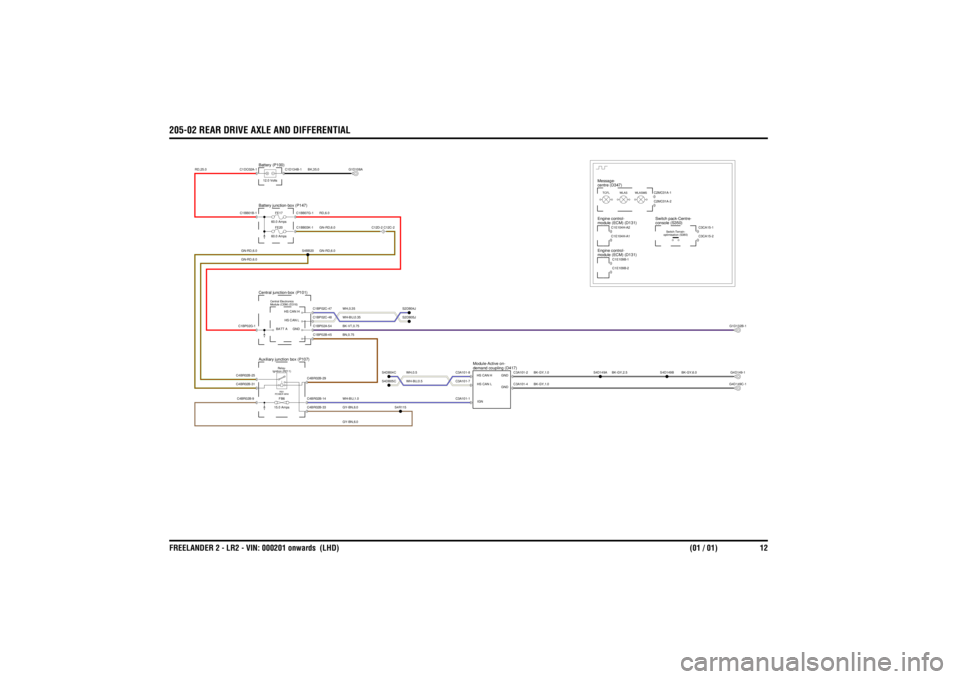
205-02 REAR DRIVE AXLE AND DIFFERENTIALFREELANDER 2 - LR2 - VIN: 000201 onwards (LHD) (01 / 01) 12
205-02 REAR DRIVE AXLE AND DIFFERENTIAL
GN-RD,6.0GN-RD,6.0
BN,0.75GY-BN,6.0GY-BN,6.0WH-BU,1.0
BK-GY,1.0BK-GY,1.0
WH,0.5WH-BU,0.5
BK-GY,2.5
BK-GY,6.0
BK-VT,0.75
GN-RD,6.0RD,6.0
WH,0.35WH-BU,0.35
BK,35.0
GN-RD,6.0
RD,25.0
FB6
15.0 AmpsIgnition (R211) Relay-RB1
POWER MINI
Auxiliary junction box (P107)
demand coupling (D417)
Module-Active on-
Module (CEM) (D316)
Central ElectronicsFE20
60.0 AmpsFE17
60.0 Amps
Central junction-box (P101)Battery junction-box (P147)Battery (P100)12.0 Volts
centre (D347)
Message-
C12D-2 C12C-2
module (ECM) (D131)
Engine control-
WLASMS
module (ECM) (D131)
Engine control-TCFL
WLAS
optimisation (S380) Switch-Terrain-
console (S350)
Switch pack-Centre-
G1D132B-1G4D149C-1G4D149-1
C4BR02B-9C4BR02B-31C4BR02B-25
C4BR02B-33C4BR02B-14C4BR02B-29
S4R115
S4DB05CS4DB04C
C3A101-1
IGNC3A101-8HS CAN HC3A101-7 HS CAN L
C3A101-2
GNDC3A101-4
GND
S4D149A
S4D149B
C1BP02G-1
HS CAN H
C1BP02C-47
GND
HS CAN L
BATT A
C1BP02B-45C1BP02A-54C1BP02C-48
C1BB01B-1
C1BB03K-1S4BB20C1BB07G-1
C1DC02A-1
C1D134B-1
S2DB04JS2DB05J
C1E109B-2C1E104H-A2C1E109B-1C1E104H-A1
C3CA15-1C3CA15-2
C2MC01A-2C2MC01A-1
G1D108A
Page 3001 of 3229
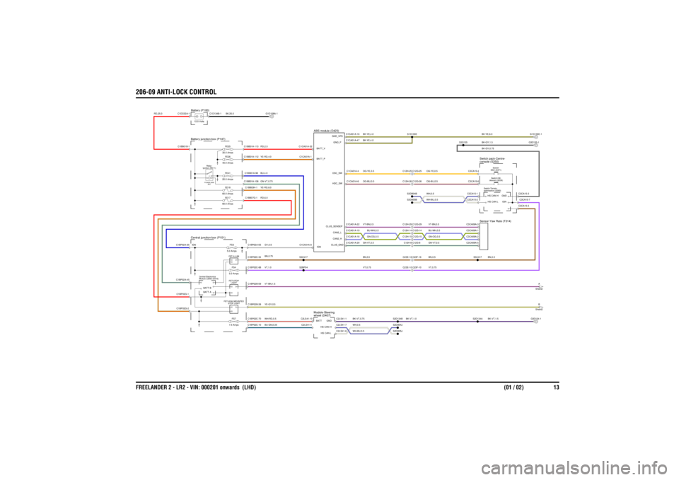
206-09 ANTI-LOCK CONTROLFREELANDER 2 - LR2 - VIN: 000201 onwards (LHD) (01 / 02) 13
206-09 ANTI-LOCK CONTROL
GN-VT,0.75
VT,0.75
YE-RD,6.0RD,6.0VT,1.0WH-RD,0.5BU-GN,0.35VT-BN,1.5YE-GY,0.5
BK-VT,1.0
WH,0.5WH-BU,0.5BK-VT,0.75
VT,0.75
BK-VT,1.5
GY,0.5YE-RD,4.0RD,2.5BN,0.75BU,4.0
BK,35.0
RD,25.0
BK-GY,0.75
WH-BU,0.5WH,0.5
BN,0.5BU-WH,0.5GN-OG,0.5GN-VT,0.5VT-BN,0.5OG-BU,0.5OG-YE,0.5
BN,0.5
BU-WH,0.5GN-OG,0.5BN,0.5GN-VT,0.5VT-BN,0.5OG-BU,0.5OG-YE,0.5
BK-YE,6.0
BK-YE,4.0BK-YE,4.0
BK-GY,1.5
FET-ILLUM
C23E-16 C23F-16
Central junction-box (P101)
FS4
5.0 AmpsFS7
7.5 AmpsLIGHT
FET-STOP
Module (CEM) (D316)
Central Electronics
STOP LIGHT
FET-HIGH MOUNTED
C23E-10 C23F-10
wheel (D407)
Module-Steering
A
Sheet2B
Sheet2
FE26
40.0 AmpsFS3
5.0 AmpsFE25
30.0 Amps
Battery junction-box (P147)
Ignition (R211) Relay-POWER MINI
RE7
FE41
20.0 AmpsFE17
60.0 AmpsFE18
60.0 Amps
Battery (P100)12.0 Volts
ABS module (D423)
C12H-8 C12G-8C12H-15 C12G-15C12H-14 C12G-14C12H-29 C12G-29C12H-25 C12G-25C12H-26 C12G-26
optimisation (S380)
Switch-Terrain-console (S350)
Switch pack-Centre-Sensor-Yaw Rate (T314)
descent (S238) Switch-Hill-DSC (S371) Switch-
C1BP02C-54
S2LN17
S3LN17
C1BP02C-70C1BP02C-10
C1BP02G-2C1BP02G-1C1BP02A-45
BATT BBATT A
C1BP02B-38C1BP02B-59C1BP02C-68
C2LS41-6
HS CAN LC2LS41-1
GNDC2LS41-7
HS CAN H
C2LS41-10 BATTC2LS41-4
S2DB05JS2D134BS2DB04J
S2BP04
S2D134A
G3D134-1
G1D108A-1
C1BP02A-65 IGN
C1BP02A-55C1BB07G-1C1BB01A-106C1BB03H-1C1BB01A-98C1BB01A-112
C1BB01B-1C1DC02A-1
C1BB01A-113
C1D134B-1
S3DB04BS3DB05B
C1CA01A-29
CLUS_GNDC1CA01A-18
CAN2_HC1CA01A-19
CAN2_LC1CA01A-22
CLUS_SENSEP
C1CA01A-8 IGN
C1CA01A-6
HDC_SWC1CA01A-4
DSC_SW
C1CA01A-1 BATT_P
C3CA15-5
C3CA09A-1C3CA09A-2C3CA09A-5C3CA09A-3
HS CAN LHS CAN H
C3CA15-1C3CA15-2C3CA15-6C3CA15-4
C3CA15-3C3CA15-7
GNDIGN
S1D130E
C1CA01A-16
GND_VPSC1CA01A-47
GND_P
C1CA01A-32 BATT_V
S3D135
G3D135-1G1D130C-1