2006 LAND ROVER FRELANDER 2 relay
[x] Cancel search: relayPage 1830 of 3229
• NOTE: The fus i bl e l inks are mount ed on t he inboard s i de of the BJB behind a series of removable covers .
The CJB is mount ed behind t he glovebox and recei ves it s main power s uppl y from the BJB. In addi ti on to cont aining bl adefus es , the CJB i s t he main controll er for a number of vehicle s ys t ems. Thes e functi ons are out li ned in t he rel evant s ect ionsof thi s manual .
The AJB is locat ed beneat h t he luggage compartment carpet , adjacent t he spare wheel wel l. The AJB i s a modular des ign,and compris es up t o 3 individual elements depending on vehicle specificati on. The AJB cont ains bl ade and J-cas e fuses ,and rel ays to di st ribute el ect ri cal power to sys t ems used at the rear of t he vehi cle. The AJB receives it s mai n power s upplyfrom the BJB.
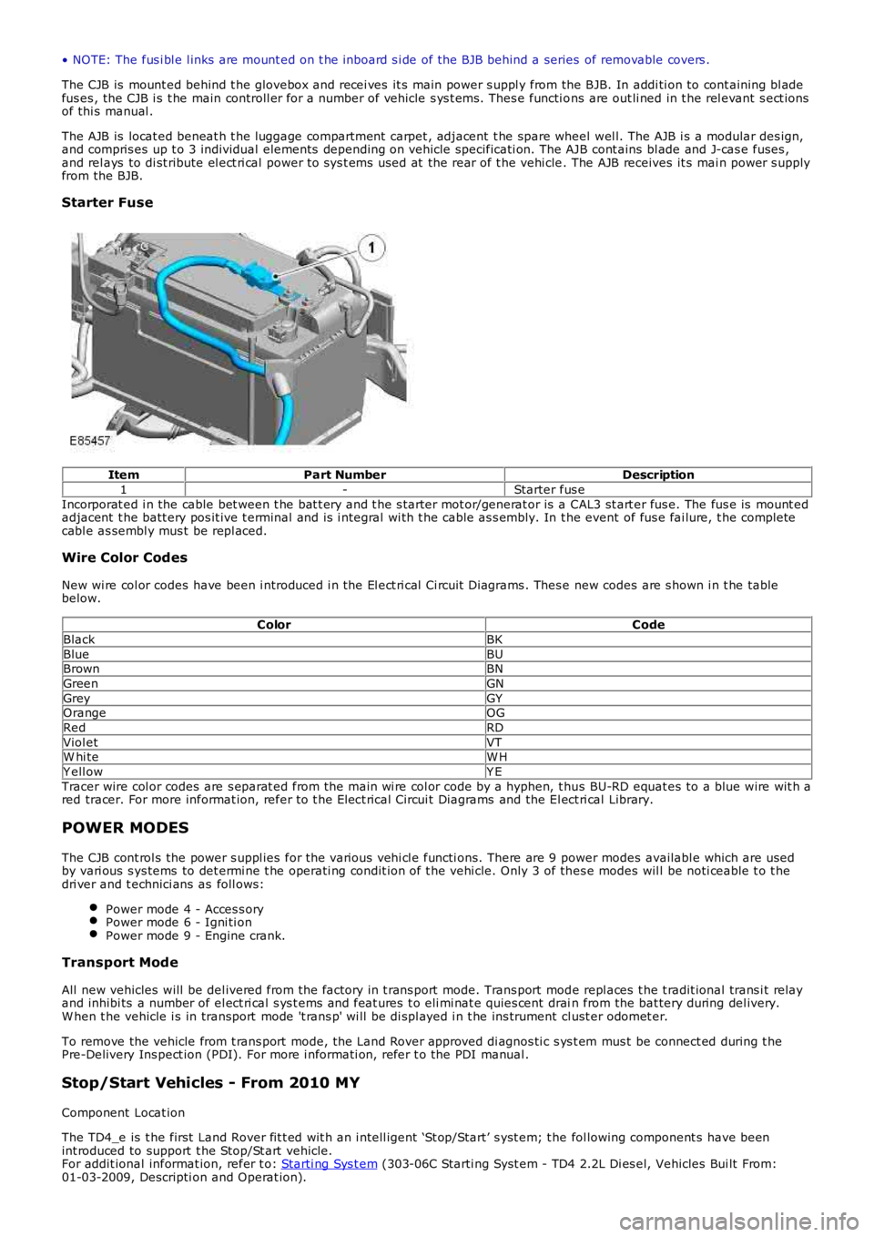
Starter Fuse
ItemPart NumberDescription
1-Starter fus e
Incorporat ed i n the cable bet ween t he bat t ery and t he s tarter mot or/generat or is a CAL3 st art er fus e. The fus e is mount edadjacent t he batt ery pos it ive t erminal and is i ntegral wi th t he cable as s embly. In the event of fus e fai lure, t he completecabl e as sembl y mus t be repl aced.
Wire Color Codes
New wi re col or codes have been i ntroduced i n the El ect ri cal Ci rcuit Di agrams . Thes e new codes are s hown i n t he tablebelow.
ColorCode
BlackBK
BlueBUBrownBN
GreenGN
GreyGYOrangeOG
RedRD
Viol etVTW hi teW H
Y ell owY E
Tracer wire col or codes are s eparat ed from the main wi re col or code by a hyphen, t hus BU-RD equat es to a blue wire wit h ared tracer. For more informat ion, refer to t he Elect rical Circui t Diagrams and the El ect ri cal Library.
POWER MODES
The CJB cont rol s the power s uppl ies for the vari ous vehi cl e functi ons. There are 9 power modes availabl e which are usedby vari ous s ys tems to det ermi ne t he operati ng condit ion of t he vehi cle. Only 3 of thes e modes wil l be noti ceable t o t hedri ver and t echnici ans as foll ows:
Power mode 4 - Acces s oryPower mode 6 - Igni ti onPower mode 9 - Engine crank.
Transport Mode
All new vehicles will be del ivered from the factory in t rans port mode. Trans port mode repl aces t he t radit ional trans i t relayand inhibi ts a number of el ect ri cal s ys t ems and feat ures t o eli mi nat e quies cent drain from the bat tery during del ivery.W hen t he vehicle i s in transport mode 't rans p' wi ll be di spl ayed i n t he ins trument cl ust er odomet er.
To remove the vehicle from t rans port mode, the Land Rover approved di agnos ti c s ys t em mus t be connect ed during t hePre-Delivery Ins pect ion (PDI). For more i nformati on, refer t o the PDI manual .
Stop/Start Vehicles - From 2010 MY
Component Locat ion
The TD4_e is t he first Land Rover fit t ed wit h an i ntell igent ‘St op/Start’ s yst em; t he fol lowing component s have beenint roduced to support t he Stop/St art vehicle.For addit ional informat ion, refer t o: Starti ng Sys t em (303-06C Starti ng Syst em - TD4 2.2L Di es el, Vehicles Bui lt From:01-03-2009, Descripti on and Operat ion).
Page 1833 of 3229
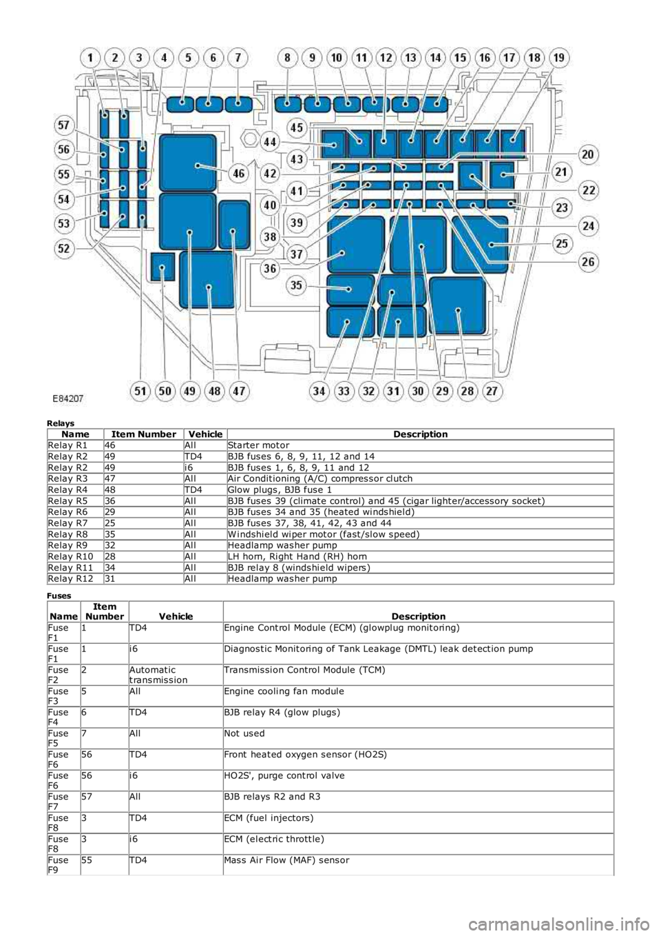
Relays
NameItem NumberVehicleDescriptionRelay R146Al lStarter mot or
Relay R249TD4BJB fus es 6, 8, 9, 11, 12 and 14
Relay R249i 6BJB fus es 1, 6, 8, 9, 11 and 12Relay R347Al lAir Condit ioning (A/C) compres s or cl utch
Relay R448TD4Glow plugs , BJB fus e 1
Relay R536Al lBJB fus es 39 (climat e control) and 45 (cigar light er/access ory socket)Relay R629Al lBJB fus es 34 and 35 (heated wi nds hiel d)
Relay R725Al lBJB fus es 37, 38, 41, 42, 43 and 44
Relay R835Al lW i ndshi el d wi per mot or (fast /sl ow s peed)Relay R932Al lHeadlamp was her pump
Relay R1028Al lLH horn, Ri ght Hand (RH) horn
Relay R1134Al lBJB rel ay 8 (winds hi eld wipers )Relay R1231Al lHeadlamp was her pump
Fuses
NameItemNumberVehicleDescription
FuseF11TD4Engine Cont rol Module (ECM) (gl owpl ug monit ori ng)
FuseF11i 6Diagnos t ic Monit ori ng of Tank Leakage (DMTL) leak det ect ion pump
FuseF22Automat ict rans mis s ionTransmis si on Control Module (TCM)
FuseF35AllEngine cooli ng fan modul e
FuseF46TD4BJB relay R4 (glow plugs)
FuseF57AllNot us ed
FuseF656TD4Front heat ed oxygen s ensor (HO2S)
FuseF656i 6HO2S', purge cont rol valve
FuseF757AllBJB relays R2 and R3
FuseF83TD4ECM (fuel injectors)
FuseF83i 6ECM (el ect ri c thrott le)
FuseF955TD4Mas s Ai r Flow (MAF) s ens or
Page 1834 of 3229
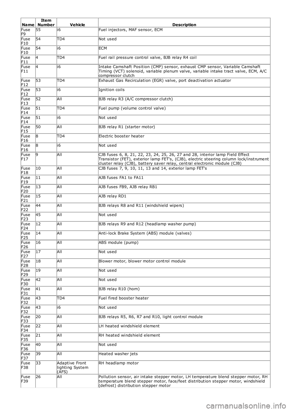
NameItemNumberVehicleDescription
FuseF955i 6Fuel inject ors , MAF s ens or, ECM
FuseF1054TD4Not us ed
FuseF1054i 6ECM
FuseF114TD4Fuel rai l press ure cont rol valve, BJB relay R4 coi l
FuseF114i 6Int ake Cams haft Pos it ion (CMP) s ens or, exhaust CMP sens or, Vari able Cams haftTi ming (VCT) s olenoi d, variable pl enum valve, variable intake t ract valve, ECM, A/Ccompres s or cl utch
FuseF1253TD4Exhaust Gas Recircul ati on (EGR) valve, port deact ivati on act uator
FuseF1253i 6Ignit ion coil s
FuseF1352AllBJB relay R3 (A/C compres sor clut ch)
FuseF1451TD4Fuel pump (vol ume cont rol valve)
FuseF1451i 6Not us ed
FuseF1550AllBJB relay R1 (s tarter mot or)
FuseF168TD4El ect ri c boos t er heat er
FuseF168i 6Not us ed
FuseF179AllCJB fus es 6, 8, 21, 22, 23, 24, 25, 26, 27 and 28, i nt eri or lamp Fi el d EffectTransi st or (FET), ext erior l amp FET's , (CJB), electric st eering col umn lock/i ns t rumentcl us t er relay (CJB), batt ery s aver relay, cent ral electronic module (CJB)
FuseF1810AllCJB fus es 7, 9, 10, 11, 13 and 14, ext erior l amp FET's
FuseF1911AllAJB fus es FA1 to FA11
FuseF2013AllAJB fus es FB9, AJB rel ay RB1
FuseF2115AllAJB relay RD1
FuseF2244AllBJB relays R8 and R11 (winds hield wipers )
FuseF2345AllNot us ed
FuseF2412AllBJB relays R9 and R12 (headl amp was her pump)
FuseF2514AllAnt i-lock Brake Sys tem (ABS) module (valves )
FuseF2616AllABS modul e (pump)
FuseF2717AllNot us ed
FuseF2818AllBl ower motor, bl ower motor cont rol module
FuseF2919AllNot us ed
FuseF3042AllNot us ed
FuseF3141AllBJB relay R10 (horn)
FuseF3243TD4Fuel fi red boos ter heater
FuseF3243i 6Not us ed
FuseF3320AllBJB relays R5, R6, R7 and R10, l ight cont rol module
FuseF3422AllLH heat ed wi nds hield element
FuseF3521AllRH heat ed wi nds hiel d element
FuseF3640AllNot us ed
FuseF3739AllHeat ed was her jets
FuseF3833Adapti ve Frontl ighti ng Sys t em(AFS)
RH headl amp mot or
FuseF3926AllPol luti on s ens or, ai r int ake st epper mot or, LH t emperat ure bl end st epper mot or, RHtemperat ure bl end st epper mot or, face/feet dis t ri but ion s t epper mot or, wi nds hield(defrost ) dis t ri but ion s t epper mot or
Page 1837 of 3229
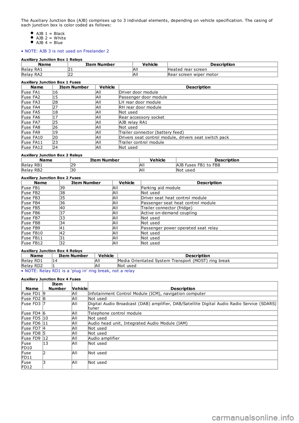
The Auxi li ary Junct ion Box (AJB) compris es up t o 3 i ndi vi dual el ement s , depending on vehicle specificati on. The casi ng ofeach junct ion box is color coded as foll ows:
AJB 1 = BlackAJB 2 = W hit eAJB 4 = Blue
• NOTE: AJB 3 i s not used on Freelander 2
Auxiliary Junction Box 1 Relays
NameItem NumberVehicleDescriptionRelay RA121AllHeat ed rear s creen
Relay RA222AllRear s creen wiper mot or
Auxiliary Junction Box 1 Fuses
NameItem NumberVehicleDescription
Fuse FA116AllDri ver door moduleFuse FA215AllPass enger door module
Fuse FA328AllLH rear door module
Fuse FA427AllRH rear door moduleFuse FA518AllNot used
Fuse FA617AllRear acces s ory socket
Fuse FA725AllAJB rel ay RA1Fuse FA826AllNot used
Fuse FA919AllTrail er connect or (bat tery feed)
Fuse FA1020AllDri vers s eat cont rol module, dri vers s eat s wi tch packFuse FA1123AllTrail er cont rol module
Fuse FA1224AllNot used
Auxiliary Junction Box 2 Relays
NameItem NumberVehicleDescriptionRelay RB129AllAJB fuses FB1 t o FB8
Relay RB230AllNot us ed
Auxiliary Junction Box 2 Fuses
NameItem NumberVehicleDescription
Fuse FB139Al lParki ng aid moduleFuse FB238Al lNot us ed
Fuse FB335Al lDriver seat heat cont rol module
Fuse FB436Al lPas senger seat heat cont rol moduleFuse FB540Al lTrai ler connector (fridge)
Fuse FB637Al lActi ve on-demand coupl ing
Fuse FB733Al lNot us edFuse FB834Al lNot us ed
Fuse FB941Al lPas senger power operat ed s eat relay
Fuse FB1042Al lNot us edFuse FB1131Al lNot us ed
Fuse FB1232Al lNot us ed
Auxiliary Junction Box 4 Relays
NameItem NumberVehicleDescriptionRelay RD114AllMedi a Orientat ed Syst em Transport (MOST) ring break
Relay RD21AllNot us ed
• NOTE: Relay RD1 is a 'plug i n' ring break, not a relay
Auxiliary Junction Box 4 Fuses
NameItemNumberVehicleDescriptionFuse FD19Al lInfotainment Control Modul e (ICM), navi gat ion computer
Fuse FD28Al lNot used
Fuse FD37Al lDigit al Audi o Broadcast (DAB) ampli fi er, DAB/Sat el li te Digit al Audi o Radi o Servi ce (SDARS)tuner
Fuse FD46Al lTel ephone control modul eFuse FD510Al lNot used
Fuse FD611Al lAudi o head unit , Int egrated Audio Modul e (IAM)
Fuse FD74Al lNot usedFuse FD85Al lNot used
Fuse FD912Al lAudi o ampli fi er
FuseFD1013Al lNot used
FuseFD112Al lNot used
FuseFD123Al lNot used
Page 1927 of 3229
The s ys t em operat es by t he AFS cont rol module recei vi ng inputs from t he engine cont rol module for engine runni ng s ignal ,t he ABS module for st eeri ng angl e and vehi cle s peed and a reverse gear i nput from the trans mi ss i on.
The AFS cont rol module proces s es thes e s ignals and provi des an output t o the headlamp leveling motors to adjus t theheadl amp hori zont al ai m according t o vehicle speed and s teering angle.
• NOTE: In market s wit h Dayt ime Running Lamps (DRL), t he AFS s yst em will not operate when the DRL are act ive.
The AFS cont rol module is connect ed on the hi gh s peed CAN bus to receive i nformat ion from other vehicle s ys tems . Thecont rol module is connect ed to the AFS power module on a dedi cat ed Local Interconnect Net work (LIN) bus . The AFScont rol module cal culat es, us ing input dat a from other s ys t ems , the requi red pos it ion of t he hori zont al adjus t ment of t heproject or modul es. The pos it ion i nformat ion is t hen output on t he LIN bus to t he AFS power module l ocat ed on eachheadl amp as sembl y. Thi s module t hen outputs the appropriate s ignal s t o power the AFS s t epper mot ors i n t he headl ampt o the appropriat e posi ti on.
The hori zont al pos it ion of t he project or modul es is dependant on a number of input vari abl es . The pos it ion i s determinedby vehi cle s peed and s teeri ng angl e. W hen reverse gear i s elected, the projector modules are moved t o t he st rai ght aheadposi ti on t o avoi d glare t o other road us ers .
The angl es of each projector module di ffer to gi ve the correct spread of light , for example, when turning l eft , the l eft handproject or modul e wi ll have a great er s wi vel ling angl e than t he right hand projector module.
In the event of a fai lure of the AFS sys tem, a warning indicator in the ins trument cl us t er flas hes t o warn the driver. TheAFS warni ng indicator i lluminates when t he i gni ti on s wit ch is i n power mode 6 and will flas h cont inuousl y unti l the faul t isrect ifi ed.
Illumi nati on of the AFS warning i ndi cat or does not neces s aril y mean t hat there is a fault wit h the AFS sys tem. The faultmay be caus ed by a fai lure of anot her sys tem s uch as st eeri ng angl e s ens or or the vehicle s peed s i gnal mi ss i ng,preventi ng the AFS s ys tem operati ng correctl y.
HEADLAMP LEVELING
Headl amp l evel ing provides for the adjus t ment of the vert ical aim of the headlamps to minimi ze glare to other road us erswhen t he vehi cl e att it ude changes due t o vehi cle l oadi ng.
Two t ypes of headlamp l evel ing are avai lable dependant on the t ype of headlamps fit ted to the vehicle:
Manual headlamp l evel ing - Hal ogen headlamps only (ROW vehicles only)Automat ic headlamp level ing - Xenon headlamps only.
Manual Headlamp Leveling - ROW Halogen Headlamps Only
Manual headlamp l evel li ng is only avai lable on RO W vehicles wit h halogen headl amps .
• NOTE: Headlamp l evel ling is not avai lable on NAS vehicles wi th hal ogen headlamps .
The manual s ys tem compris es t he fol lowing components :
Two headlamp l evel ling motorsHeadl amp l evel ing rheos tat rotary cont rol .
W hen t he i gni ti on is i n i gni ti on power mode 6, power i s s uppli ed t o t he li ght control modul e via t he i gni ti on rel ay in t heBJB and a fuse in t he CJB. Power i s als o s uppl ied vi a the ignit ion relay i n the BJB to t he headlamp l evel ing mot or in eachheadl amp as sembl y.
Movement of t he leveli ng rot ary control produces a variable volt age output, whi ch is s ens ed by the motors. The mot orsreact to the suppli ed vol tage and move the headlamp t o t he reques ted pos it ion whi ch rel at es t o t he suppli ed volt age fromt he leveling rotary cont rol . The headlamps can onl y be lowered from t heir unladen posi ti on t o compens ate for changes invehi cl e at ti tude due t o l oading.
The manual headlamp level ing rotary cont rol has no defi ned pos i ti ons whi ch rel at e t o t he vehi cle l oadi ng. The approximat erot ary t humbwheel control pos it ion for a given l oadi ng is s hown i n t he fol lowing t able:
R otary Control RotationVehicle Load
0Driver only or Driver and front s eat pass enger1/4Driver and pass engers i n all s eats
½Maxi mum gross vehicle weight
FullMaxi mum rear axl e load
Automatic Headlamp Leveling - Xenon Headlamps Only
Automat ic headlamp level ing i s only avail abl e on vehicles wi th xenon headlamps . The sys tem is not a Dynami c headl amplevell ing s yst em and changes in vehicle inclinat ion due t o pos it ive and negat ive accelerat ion are not compens ated.
Automat ic headlamp level ing provi des for t he st ati c, periodic adjus t ment of the vertical aim of the headlamps t o mi nimi s eglare to other road us ers when the vehicle at t it ude changes due to loading.
Automat ic headlamp level ing i s cont rol led by a headlamp leveli ng modul e whi ch is l ocat ed on the bul khead, adjacent t ot he ins trument panel on t he pas s enger s ide 'A' pill ar.
• NOTE: On vehicles wit h the AFS sys tem, the headlamp l evel ing s oft ware is i ncorporated i nto the AFS control modul e andt he modul e i s known as the AFS control modul e.
The headl amp l eveli ng s ys t em compri s es the foll owing component s and informat ion from other vehi cl e s yst ems :
Front and rear vehicle height s ensorsTwo headlamp l evel ing, verti cal adjus t ment motors
Page 2053 of 3229
Peri meter mode only monit ors t he hinged panel s and validi ty of t he remot e handset i n t he s tart cont rol module. Perimet ermode i s act ivat ed by a s ingle pres s of the l ock but ton on the remot e hands et.
Volumet ri c Mode
Volumet ri c mode monit ors t he vehicle i nterior for i nt rus i on. If the vehicle is fit t ed wit h a bat tery backed s ounder, whi chincorporat es a t il t sens or, t he vehi cl e at ti tude i s als o moni tored when vol umetric mode is acti ve. Volumet ri c mode i sact ivat ed by a s econd press of t he l ock but ton on the remote hands et. The s econd press of t he butt on mus t occur wi thin 3s econds of the firs t pres s. The s econd pres s of the l ock but ton al s o act ivat es the perimet er mode doubl e locking feat ure.
The CJB arms the act ive anti -t heft s yst em when it l ocks or doubl e locks the vehicl e, provi ding all t he fol lowi ng condit ionsare met:
All doors , li ft gate and hood are clos edThe CJB is not i n t rans it mode.
W hen t he vehicle has s ucces s full y completed it s locki ng rout ine, confirmati on wil l be given by a s i ngl e flas h of the t urns ignal indicators to indicate the l ocked condi ti on. If doubl e locking i s act ivat ed, t hen the confi rmat ion wil l be gi ven by adoubl e flas h of the t urn si gnal i ndi cat ors ; one flas h for l ocked and one long flas h for double locked.
Mislock
If any doors , l iftgate or hood i s open when a l ock or double l ock reques t i s received, the acti ve anti -t heft alarm s ys temremai ns dis armed and the CJB generat es a s hort mi sl ock sound from the vehicle horns or bat t ery backed s ounder and t het urn s ignal indicators wil l not flas h. Each at t empt to l ock wil l be confi rmed by an audible chime being emi tt ed.
W hen t he CJB arms the act ive anti -t heft s ys tem, i t fi rs t enabl es perimet er mode and monit ors the s t atus of t he hingedpanel s. If t he vehi cl e is fi tt ed wit h a bat t ery backed s ounder, an arming s ignal is s ent from t he CJB t o enabl e t he s ounder.If the vehicle is double l ocked and fit ted wi th an int rus ion det ect ion modul e, t he CJB t hen sends an arming s i gnal t o t hemodule and t he t il t sens or when doubl e locked. The CJB i gnores the s i gnals from t he int rus ion det ect ion modul e for t hefi rs t 30 s econds t o al low t ime for t he vehi cle i nteri or to set tl e and prevent fal se al arm act ivat ion.
If the l iftgate is opened via t he remote hands et , t he int rus ion det ect ion module and the t il t s ens or are inhibit ed unti l theli ft gate i s clos ed.
Disarming
The CJB wil l dis arm the act ive anti -t heft s yst em to prevent fals e alarm acti vat ion under cert ai n condi ti ons as foll ows :
W hen t he acti ve ant i-t heft s ys t em i s armed in volumet ri c mode, if t he vehi cl e batt ery vol tage decreases t o l esst han 9 vol ts , t he CJB wil l dis abl e t he vol umetric mode and remai n in perimet er mode only. Thi s prevents fals ealarm acti vat ion because the i ntrusi on detecti on module cannot operat e correct ly below 9 volt s .On vehicles fit ted wit h a bat tery backed s ounder, i f the vehicl e batt ery volt age decreas es from 9.5 t o 9 vol ts inmore than a 30 mi nut e peri od, t he CJB de-acti vat es t he batt ery backed sounder and, if requi red, wil l use thevehi cl e horns t o s ound an audible al arm t rigger warni ng. This prevent s fal s e alarm acti vat ion. At volt ages below 9volt s, t he CJB wil l not generat e t he 'heart beat ' si gnal t o t he batt ery backed sounder. The batt ery backed sounderint erpret s t his as t he CJB has been tampered wit h and acti vat es it s s ounder. If t he batt ery volt age s ubs equent lyri s es to more than 9.5 vol ts , t he CJB wil l re-arm the bat tery backed s ounder.If the vehicle is unlocked usi ng the unl ock but ton on the remote hands et and, wi thi n 60 s econds a hi nged panel isnot opened, the CJB aut omati call y re-locks t he vehi cl e and re-arms the act ive anti -theft s yst em (i f the 'aut o re-l ock'feat ure i s enabl ed). This prevent s leaving t he vehi cl e unlocked and dis armed by accidental operati on of the remot ehands et unlock but t on.
Alarm
W hen t he alarm i s t ri ggered, t he CJB act ivat es audi bl e and vis ual warnings . The audible warnings are produced by t hevehi cl e's horns or t he batt ery backed s ounder. Vi si ble i ndi cat ions are produced us i ng the t urn si gnal i ndi cat ors .
The CJB act ivat es the vehicle horns or bat t ery backed s ounder and t he vis ual indicati ons for 30 s econds. The act ivati on iss topped for 5 seconds and, i f the al arm trigger is s t ill present , the CJB wi ll cycl e agai n for 30 seconds (60 s econds i ncert ai n market s ). This will be repeat ed for up to a maximum of 10 cycles (3 cycles in certai n market s) of 30 seconds (60s econds in certai n market s) for any one armi ng period. The CJB wi ll de-acti vat e t he alarm i f the 10 cycles (3 cycl es incert ai n market s ) have been complet ed and the al arm t rigger is st il l pres ent or unti l it recei ves a dis arm s ignal .
• NOTE: If the bat tery backed s ounder is triggered due t o t amper det ect ion, t he vi s ual i ndi cat ion us ing the t urn si gnalindicat ors i s not act ivated.
The alarm can be t ri ggered by any of the hi nged panels bei ng opened, the intrus ion detecti on module det ect s a movementins ide the vehicle, t he ti lt s ensor det ect s vehi cl e movement or an ignit ion t amper is det ect ed (inval id remot e hands et).
Battery Backed Sounder
W hen t he CJB arms the act ive anti -t heft s ys tem, i n eit her t he peri meter mode or t he volumet ri c mode, t he CJB s ends anarming s ignal to the bat tery backed s ounder on t he LIN bus . W hen the s ys tem is armed i n the vol umetric mode, t he CJBals o s ends an arming s ignal to the t il t s ens or (i f fi tt ed).
• NOTE: If a batt ery backed sounder is fit ted, it i s als o armed wi th the perimet er mode lock request .
On recei pt of t he arming s ignals , t he s ounder and the ti lt s ens or res pond wit h a st atus mess age. If t he CJB does notreceive t he s tat us s ignals wi thi n 12 s econds , the CJB as s umes there is a fault and res ponds wi th a dis arm s ignal to ei thert he sounder and/or the t il t s ens or and s tores a rel at ed faul t code. If the s ounder is dis armed when the act ive anti -t hefts ys t em i s armed and the sys tem is subs equent ly t ri ggered, t he CJB energizes t he horn relay and us es the vehicl e horns t os ound the audible warning in pl ace of t he s ounder.
W hen t he s ounder is armed, t he CJB sends a periodic (heartbeat ) si gnal t o t he s ounder which prompt s t he s ounder tomonit or the vehicle bat t ery s uppl y and t he LIN bus link wit h the CJB. The s ounder wil l operate if:
Page 2061 of 3229
opened. The remot e handset i s removed from the st art control modul e by gentl y pushi ng the remote hands et int o t he st artcont rol module and releas ing. The s tart cont rol module mot or wil l then drive t he remot e hands et out from t he s lot as l ongas t he ignit ion i s off.
RF RECEIVER
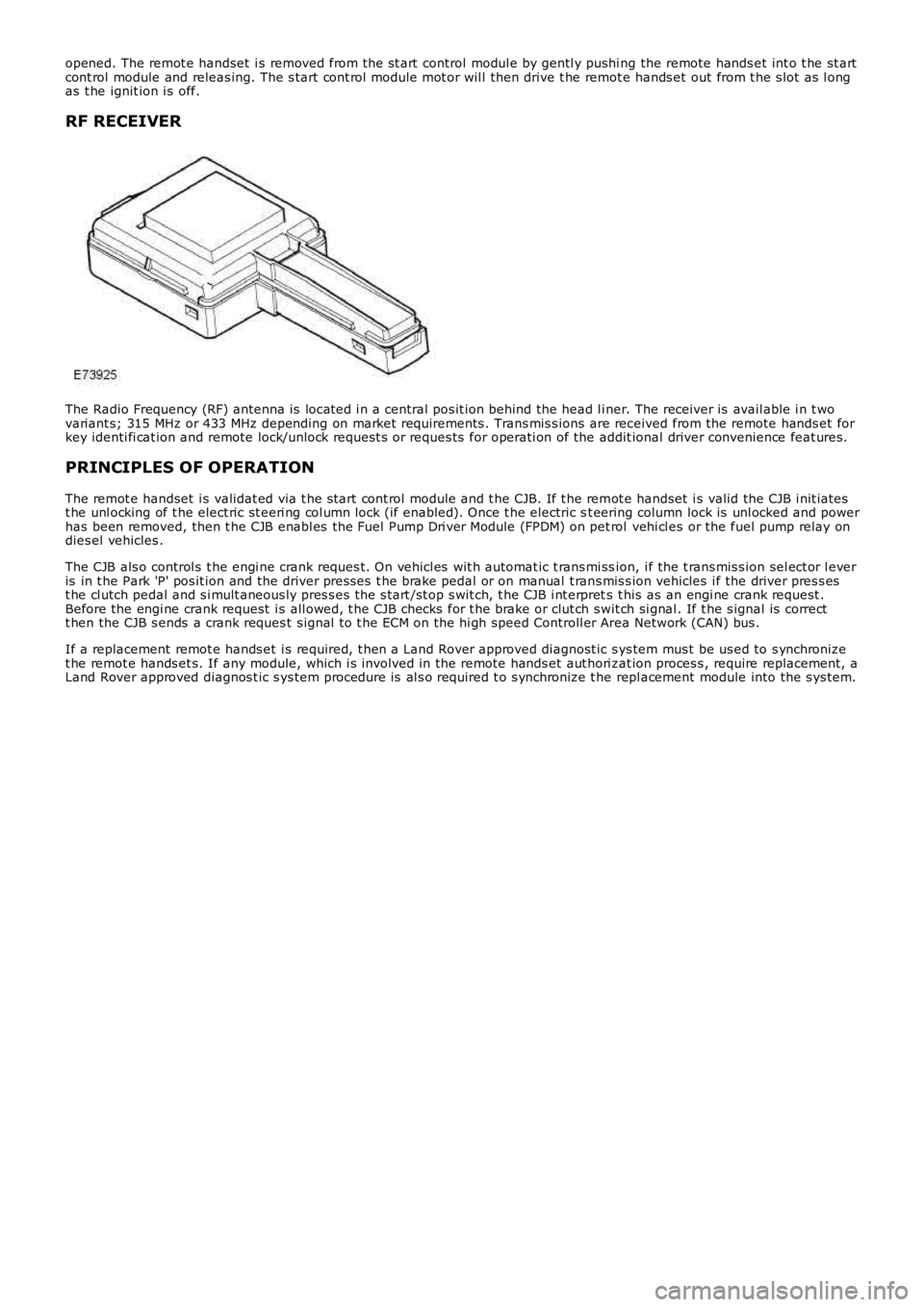
The Radio Frequency (RF) antenna is locat ed i n a central pos it ion behind the head l iner. The receiver is avail able i n t wovariant s; 315 MHz or 433 MHz depending on market requirements . Trans mis s ions are received from the remote hands et forkey identi fi cat ion and remote lock/unlock request s or reques ts for operati on of the addit ional driver convenience feat ures.
PRINCIPLES OF OPERATION
The remot e handset i s validat ed via t he s tart cont rol module and t he CJB. If t he remot e handset i s valid the CJB i nit iatest he unl ocking of t he elect ric st eeri ng col umn lock (if enabled). Once t he electric st eering column lock is unl ocked and powerhas been removed, then t he CJB enabl es the Fuel Pump Dri ver Module (FPDM) on pet rol vehi cl es or the fuel pump relay ondies el vehicles .
The CJB als o control s t he engi ne crank reques t. On vehicl es wit h automat ic t rans mi ssion, i f the t rans mis s ion sel ect or l everis in t he Park 'P' pos it ion and the driver pres ses t he brake pedal or on manual t rans mis s ion vehicles i f the driver pres s est he cl utch pedal and s i mult aneous ly pres s es t he s tart /st op s wit ch, t he CJB i nt erprets t his as an engi ne crank request .Before the engi ne crank request i s all owed, t he CJB checks for t he brake or clut ch swit ch si gnal . If t he s ignal is correctt hen the CJB s ends a crank reques t s ignal t o t he ECM on the hi gh speed Controll er Area Network (CAN) bus .
If a replacement remot e hands et i s required, t hen a Land Rover approved diagnost ic sys tem mus t be us ed to s ynchronizet he remot e hands et s. If any module, which i s involved in the remote hands et aut hori zat ion proces s , require replacement, aLand Rover approved diagnos t ic s ys tem procedure is al s o required t o s ynchronize t he repl acement module into the s ys tem.
Page 2062 of 3229
Publi s hed: 11-May-2011
Anti-Theft - Passive - Anti-Theft - Passive
Diagnosi s and Tes ti ng
Principles of Operation
For a detail ed descripti on of the Pas s ive Ant i-Theft Sys t em (PATS), refer t o t he relevant Des cript ion and Operat ion secti onin the workshop manual.REFER to: Ant i-Theft - Pas s ive (419-01B Anti -Theft - Pas s ive, Descripti on and Operat ion).
Inspection and Verification
The best method t o confirm the correct operat ion of t he Pass i ve Ant i-Theft Syst em (PATS) is t o check t he LED (located i nt he cent er of t he ins t rument panel ). The LED s hould i ll uminate sol id for 3 s econds , when the i gnit ion s tat us is set t o ON,and t hen ext inguis h. Thi s validat es all PATS functi ons (i .e. the key t rans ponder matches a st ored key code, thechal lenge/res ponse sequence bet ween t he res pect ive modules was succes s ful res ult ing in t he EMS being enabled).
Ignition Fails to Operate
Check t hat the key i s correct ly i nserted i nto the s t art cont rol unit (SCU) and that i t is t he correct key for t he vehi cle (Keywil l be ejected from t he SCU i f it is not programmed or from anot her vehicl e). If the vehicle is an aut omati c, ens ure t hatt he Park pos it ion i s s el ect ed and if manual, ens ure it is in t he Neutral pos i ti on.
Check t hat the st art but ton circui t to the Cent ral Juncti on Box (CJB) i s not open circui t or s hort to ground.
Check t hat the CAN network is not mal functi oni ng, i .e. open circuit or s hort circui t. This woul d mean t hat the CJB, ECM andIns t rument Clus t er woul d be unabl e t o communicate. Check thes e modules for relat ed DTCs and refer t o relevant DTCIndex.
Engine Fails to Crank
The immobili zer s t atus i ndi cat ion LED i s dis played i n the bot tom left of the i nst rument pack. W hen the key i s i ns ert ed i nt ot he SCU, t he LED wi ll be t urned on for 3 s econds and t hen turned off. The LED will flas h s lowl y (once every 2 seconds ) i ft he vehi cl e is immobi lis ed (t ransponder not approved). Addit ionall y the di agnos ti c syst em s hould be us ed t o check forDiagnost ic Troubl e Codes (DTCs ) from the CJB, ins trument cl ust er, ECM and the ABS modul e.
One potent ial occurrence for the vehicl e fai ling to crank on an Automat ic Trans mi s sion coul d be due t o t he Locked in parks wit ch.
Check t he Crank reques t circui t from t he CJB t o ECM for short ci rcuit or open circuit .
Check t he St art er Rel ay Circuit .
Check t hat the St eeri ng Col umn Lock (SCL) is operat ing correctl y. Ins erti ng t he key should drive t he SCL t o un-l ock ands teeri ng wheel should move freel y.
Check t he CAN net work i s not malfunct ioning, i.e. the CAN ci rcuit i s open or short ci rcuit . Thi s would mean that t he CJB,ins t rument clus ter, ECM or ABS module would not be abl e t o communicate res ul ti ng in no chal lenge being made from t hemodules for the Immobil is ati on data.
Als o on an Aut omat ic, check the CAN network between t he CJB and the Transmis s ion Control Modul e (TCM). The CJB usest he "LockedInP" s ignal transmit ted by t he TCM to det ermi ne if t he t rans mis s ion i s in Park before all owing crank, the CJBus es a value of 0x01, i f the CJB s ees a value l ess than t his i t wil l not al low crank, and key wil l not be ejected from SCU.
For a manual gearbox t he clut ch pedal has to be de-pres s ed, hence check t he CAN network between t he CJB and t he ECMt o ensure t he cl utch i s depress ed, Clut chPedal Swit ch75pct = TRUE and Cl ut chPedalPress ed2 = True. The Vehicl e wil l notcrank unti l thes e s ignals are s et.
On an Aut omati c vehi cl e, check t he CAN network between t he ABS module and the CJB. The CJB uses a s ignal"BrakePedalActi ve" t o det ermi ne if t he brake pedal has been depres sed in order t o allow t he engine t o crank. The CJB us esa value = TRUE i f the CJB does not receive t hi s s ignal, i t wil l not al low t he crank reques t output.
Engine Cranks But Will Not Start
If the engine i s cranking i t means that t he EMS has pass ed t he authori s at ion required wit h t he CJB. If thi s authori s at ionfai led, the ECM would not engage the s t art er relay. Thi s coul d be confi rmed by verifyi ng t he LED in the l eft of t heIns t rument pack bei ng il lumi nat ed for 3 seconds on Key ins ert ion, or by reading DTCs from t he CJB or t he ECM.
In all cases of s us pected non-st art i s sues , the most l ogical fail ure modes s houl d be el imi nat ed first . i.e.
1. Check al l relevant suppli es and grounds to the relevant modul es are ok.2. Note any unus ual behavi our from other s yst ems /funct ionali ty.3. Note any funct ions t hat are not operati ng as expect ed.
Fault Codes/DTCs
For the vari ous PATS modes of operat ion/fail ures l is ted i n t he t abl e, t he CJB wi ll store a DTC whi ch wil l not be shown t ot he cus t omer.
W hen t he Key i s ins ert ed and ignit ion st atus ON is achieved, if t he s tart aut horis ation pas ses , the LED in t he bott om leftof the ins trument cl us t er will i ll uminate for 3 s econds t hen go off. If st art aut horis ati on fai ls , the LED wil l conti nue to fl as hevery 2 s econds . Pleas e s ee tabl e below for a li s t of fault codes that wil l be s tored under cert ain condi ti ons. For addi ti onalinformat ion.REFER to: St art ing Syst em (303-06A St art ing Sys tem - I6 3.2L Petrol, Di agnos is and Tes ti ng) /