2006 LAND ROVER FRELANDER 2 relay
[x] Cancel search: relayPage 1556 of 3229
Publi shed: 13-Jul-2011
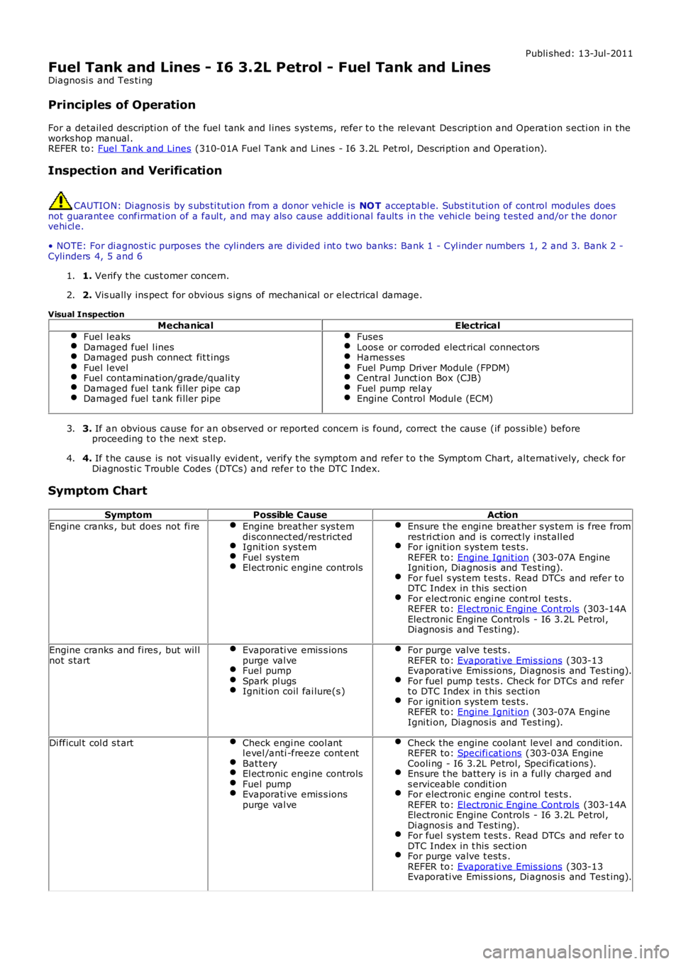
Fuel Tank and Lines - I6 3.2L Petrol - Fuel Tank and Lines
Diagnosi s and Tes ti ng
Principles of Operation
For a detail ed descripti on of the fuel tank and l ines s ys t ems , refer t o t he rel evant Des cript ion and Operat ion s ecti on in theworks hop manual .REFER to: Fuel Tank and Lines (310-01A Fuel Tank and Lines - I6 3.2L Pet rol , Descri pti on and Operat ion).
Inspection and Verification
CAUTION: Di agnos is by s ubs ti tut ion from a donor vehicle is NO T acceptabl e. Subs ti tut ion of cont rol modules doesnot guarant ee confirmat ion of a faul t, and may als o caus e addit ional fault s i n t he vehi cl e being t est ed and/or t he donorvehi cl e.
• NOTE: For di agnos t ic purpos es the cyli nders are divided i nt o t wo banks: Bank 1 - Cyl inder numbers 1, 2 and 3. Bank 2 -Cylinders 4, 5 and 6
1. Verify t he cus t omer concern.1.
2. Vis ually ins pect for obvious s igns of mechani cal or electrical damage.2.
Visual Inspection
MechanicalElectricalFuel l eaksDamaged fuel l inesDamaged push connect fit t ingsFuel l evelFuel contami nati on/grade/quali tyDamaged fuel t ank fi ller pipe capDamaged fuel t ank fi ller pipe
FusesLoos e or corroded elect rical connect orsHarnes s esFuel Pump Dri ver Module (FPDM)Central Junct ion Box (CJB)Fuel pump relayEngine Control Modul e (ECM)
3. If an obvious cause for an obs erved or report ed concern is found, correct t he caus e (if pos s ible) beforeproceeding t o t he next s t ep.3.
4. If t he caus e is not vis ually evi dent , verify t he sympt om and refer t o t he Sympt om Chart, al ternat ively, check forDi agnos ti c Trouble Codes (DTCs) and refer t o t he DTC Index.4.
Symptom Chart
SymptomPossible CauseAction
Engine cranks , but does not fi reEngine breat her sys temdi sconnect ed/res trict edIgnit ion s yst emFuel sys temEl ect ronic engine controls
Ens ure t he engi ne breat her s ys tem is free fromres t ri ct ion and is correct ly i nst all edFor ignit ion s ys tem tes t s.REFER to: Engine Ignit ion (303-07A EngineIgni ti on, Di agnos is and Tes t ing).For fuel s ys t em t est s . Read DTCs and refer t oDTC Index in t his secti onFor elect roni c engi ne cont rol t es t s .REFER to: El ect ronic Engine Cont rols (303-14AElectronic Engine Controls - I6 3.2L Petrol ,Di agnos is and Tes ti ng).
Engine cranks and fires , but wil lnot s tartEvaporati ve emis s ionspurge val veFuel pumpSpark pl ugsIgnit ion coil fai lure(s )
For purge valve t est s .REFER to: Evaporati ve Emis s ions (303-13Evaporati ve Emis s ions, Di agnos is and Tes t ing).For fuel pump t es t s . Check for DTCs and refert o DTC Index in t his s ecti onFor ignit ion s ys tem tes t s.REFER to: Engine Ignit ion (303-07A EngineIgni ti on, Di agnos is and Tes t ing).
Di fficul t col d s t artCheck engi ne cool antl evel /anti -freeze cont entBat teryEl ect ronic engine controlsFuel pumpEvaporati ve emis s ionspurge val ve
Check the engine coolant level and condit ion.REFER to: Specifi cat ions (303-03A EngineCooli ng - I6 3.2L Petrol, Speci fi cat ions ).Ens ure t he batt ery i s in a ful ly charged ands erviceable condi ti onFor elect roni c engi ne cont rol t es t s .REFER to: El ect ronic Engine Cont rols (303-14AElectronic Engine Controls - I6 3.2L Petrol ,Di agnos is and Tes ti ng).For fuel s ys t em t est s . Read DTCs and refer t oDTC Index in t his secti onFor purge valve t est s .REFER to: Evaporati ve Emis s ions (303-13Evaporati ve Emis s ions, Di agnos is and Tes t ing).
Page 1557 of 3229
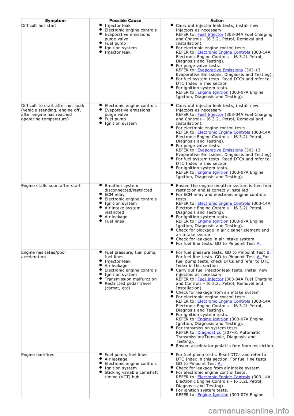
SymptomPossible CauseAction
Di fficul t hot st artInjector l eakEl ect ronic engine controlsEvaporati ve emis s ionspurge val veFuel pumpIgnit ion s yst emInjector l eak
Carry out inject or leak tes t s, i nst all newi nject ors as neces sary.REFER to: Fuel Inject or (303-04A Fuel Chargingand Controls - I6 3.2L Pet rol , Removal andInst all at ion).For elect roni c engi ne cont rol t es t s .REFER to: El ect ronic Engine Cont rols (303-14AElectronic Engine Controls - I6 3.2L Petrol ,Di agnos is and Tes ti ng).For purge valve t est s .REFER to: Evaporati ve Emis s ions (303-13Evaporati ve Emis s ions, Di agnos is and Tes t ing).For fuel s ys t em t est s . Read DTCs and refer t oDTC Index in t his secti onFor ignit ion s ys tem tes t s.REFER to: Engine Ignit ion (303-07A EngineIgni ti on, Di agnos is and Tes t ing).
Di fficul t t o s tart aft er hot s oak(vehi cl e s tanding, engi ne off,aft er engi ne has reachedoperat ing t emperature)
El ect ronic engine controlsEvaporati ve emis s ionspurge val veFuel pumpIgnit ion s yst em
Carry out inject or leak tes t s, i nst all newi nject ors as neces sary.REFER to: Fuel Inject or (303-04A Fuel Chargingand Controls - I6 3.2L Pet rol , Removal andInst all at ion).For elect roni c engi ne cont rol t es t s .REFER to: El ect ronic Engine Cont rols (303-14AElectronic Engine Controls - I6 3.2L Petrol ,Di agnos is and Tes ti ng).For purge valve t est s .REFER to: Evaporati ve Emis s ions (303-13Evaporati ve Emis s ions, Di agnos is and Tes t ing).For fuel s ys t em t est s . Read DTCs and refer t oDTC Index in t his secti onFor ignit ion s ys tem tes t s.REFER to: Engine Ignit ion (303-07A EngineIgni ti on, Di agnos is and Tes t ing).
Engine s t al ls s oon after s tartBreat her sys temdi sconnect ed/res trict edECM relayEl ect ronic engine controlsIgnit ion s yst emAi r intake s ys temrest ri ctedAi r leakageFuel lines
Ens ure t he engi ne breat her s ys tem is free fromres t ri ct ion and is correct ly i nst all edFor ECM rel ay and electroni c engi ne cont rol st est s .REFER to: El ect ronic Engine Cont rols (303-14AElectronic Engine Controls - I6 3.2L Petrol ,Di agnos is and Tes ti ng).For ignit ion s ys tem tes t s.REFER to: Engine Ignit ion (303-07A EngineIgni ti on, Di agnos is and Tes t ing).Check for blockage i n air cl eaner element andair i ntake s yst emCheck for leakage in ai r int ake sys temFor fuel li ne tes t s. GO to Pinpoint Test A.
Engine hes it at es /pooraccel erati onFuel pres sure, fuel pump,fuel l inesInjector l eakAi r leakageEl ect ronic engine controlsIgnit ion s yst emTrans mi ss i on malfunct ionRes trict ed pedal t ravel(carpet, et c)
For fuel pres sure t est s . GO t o Pinpoint Tes t B.For fuel li ne tes t s. GO to Pinpoint Test A. Forfuel pump t es ts , check DTCs and refer to DTCIndex i n t his s ecti onCarry out fuel inject or leak t es t s, i nst all newi nject ors as neces sary.REFER to: Fuel Inject or (303-04A Fuel Chargingand Controls - I6 3.2L Pet rol , Removal andInst all at ion).Check for leakage from ai r intake s ys temFor elect roni c engi ne cont rol t es t s .REFER to: El ect ronic Engine Cont rols (303-14AElectronic Engine Controls - I6 3.2L Petrol ,Di agnos is and Tes ti ng).For ignit ion s ys tem tes t s.REFER to: Engine Ignit ion (303-07A EngineIgni ti on, Di agnos is and Tes t ing).For trans mi s si on s ys t em t es ts .REFER to: Di agnos ti cs (307-01 Aut omati cTrans mi ss ion/Transaxle, Di agnos is andTes ti ng).Ens ure accel erator pedal i s free from res t rict ion
Engine backfiresFuel pump, fuel l inesAi r leakageEl ect ronic engine controlsIgnit ion s yst emSt icking vari abl e cams haftt iming (VCT) hub
For fuel pump t es t s . Read DTCs and refer t oDTC Index in t his secti on. For fuel l ine t est s .GO to Pi npoi nt Tes t A.Check for leakage from ai r intake s ys temFor elect roni c engi ne cont rol t es t s .REFER to: El ect ronic Engine Cont rols (303-14AElectronic Engine Controls - I6 3.2L Petrol ,Di agnos is and Tes ti ng).For ignit ion s ys tem tes t s.REFER to: Engine Ignit ion (303-07A Engine
Page 1585 of 3229
The fuel deli very module flange i s s eal ed to the t ank wit h an O-ring and s ecured wi th a locki ng ring.
The lower part of t he fuel deli very module forms the fuel del ivery pot , and provides the locat ion for the in-t ank pump andt he 2 jet pumps . The delivery pot provi des a cons t ant res ervoir of fuel for t he engine drawn fuel supply. The engine fuels uppl y and ret urn l ines are immers ed in the del ivery pot .
The delivery pot is mai ntained full by t he 2 jet pumps . The i n-t ank pump draws fuel from wit hin the fuel deli very pot andforces the fuel t hrough t he 2 jet pumps . The flow of fuel t hrough each jet pump creat es a venturi effect t hat draws fuelfrom bot h s ides of t he fuel tank i nto the fuel deli very pot. Surpl us fuel entering the fuel deli very pot overflows into theus abl e s ide of t he fuel t ank.
A valve i s l ocated in t he l ower (usabl e tank s i de) jet pump s uppl y ori fi ce. The valve i s open when the i n-t ank pump isenergized and t he lower jet pump is s upplying fuel i nto the fuel del ivery pot . The val ve wil l cl os e when the i n-t ank pump isde-energized t o prevent fuel drai ni ng from the fuel del ivery pot .
The in-tank pump is energized by t he fuel pump relay l ocat ed in the Cent ral Juncti on Box (CJB). The Engine Cont rol Module(ECM) energi zes the fuel pump relay at al l ti mes when t he ignit ion i s in power modes 4 (Acces s ory) t o 9 (Engi ne crank).For addit ional informat ion, refer t o: Electroni c Engi ne Controls - 2.2L Dies el (303-14 El ect ronic Engine Cont rols - 2.2LDies el, Des cript ion and Operat ion).
A modi fi ed fuel delivery modul e i s ins tal led for col d climat e market vehicl es that feat ure a fuel fi red boos ter heater andauxi li ary fuel pump. The modified fuel del ivery modul e incorporat es a s eparate fuel supply line that connects t o anauxi li ary fuel pump, mounted on the ext erior RH si de of the tank. An addi ti onal fuel l ine connects the auxil iary fuel pumpt o the fuel fi red boos ter heat er.For addit ional informat ion, refer t o: Fuel Fired Boost er Heat er (412-02B Auxi liary Cli mate Cont rol , Des cri pti on andOperat ion).
Fuel Sender Units
The 2 MAPPS fuel s ender uni ts are located on eit her s ide of t he s addl e s haped tank, and connect t o t he int ernal elect ricalconnecti ons on the fuel del ivery modul e fl ange. Each s ens or provides an elect rical signal t o t he CJB t hat i s proport ionatet o the fuel level i n each s ide of t he tank.
The act ual fuel level i n t he t ank i s calculated by the CJB and t rans mit t ed via t he medium s peed Cont roll er Area Net work(CAN) bus t o t he ins t rument clus ter.
A warning l amp is incorporat ed in t he i ns t rument clus ter and wi ll il lumi nat e when t he fuel l evel is at, or below apredetermined l evel . On vehi cles wi th a high-l ine i nst rument clus ter, a mes s age is di spl ayed and a chi me i s s ounded t oinform the driver to refuel .
For addit ional informat ion, refer t o:
Ins trument Clus ter (413-01 Ins t rument Clus t er, Descripti on and Operat ion),Informat ion and Mes s age Cent er (413-08 Informati on and Mes sage Cent er, Descripti on and Operat ion).
Fuel Tank Breather Valve
The breat her valve i s located i n t he fuel t ank and is connected to the fuel deli very module fl ange vi a an i nt ernal breatherhose. The breat her valve al lows ai r to es cape and ent er the fuel tank t o compens at e for t he changing vol ume wit hin thet ank.
FUEL TANK FILLER
Page 1591 of 3229
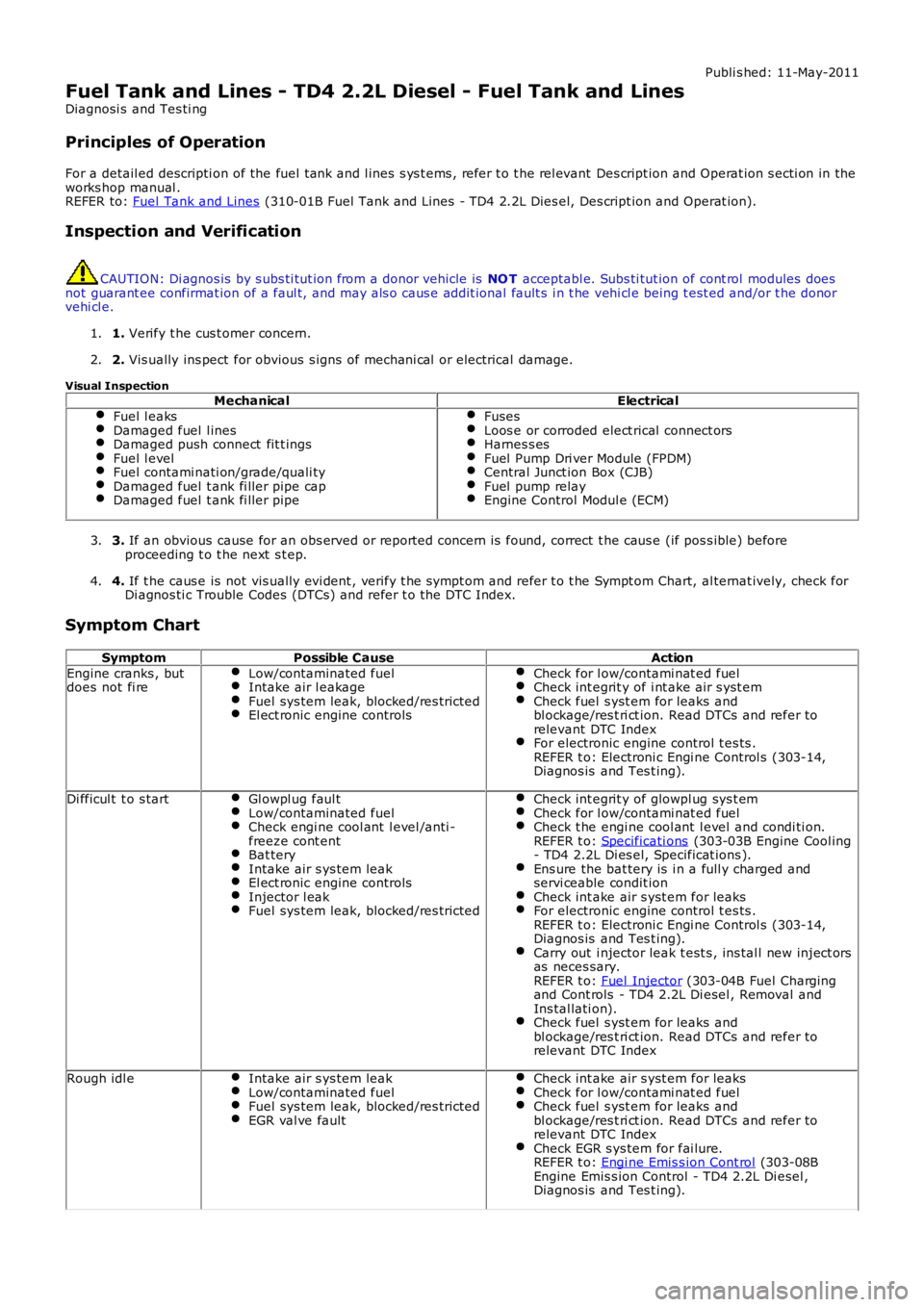
Publi s hed: 11-May-2011
Fuel Tank and Lines - TD4 2.2L Diesel - Fuel Tank and Lines
Diagnosi s and Tes ti ng
Principles of Operation
For a detail ed descripti on of the fuel tank and l ines s ys t ems , refer t o t he rel evant Des cript ion and Operat ion s ecti on in the
works hop manual .
REFER to: Fuel Tank and Lines (310-01B Fuel Tank and Lines - TD4 2.2L Dies el, Des cript ion and Operat ion).
Inspection and Verification CAUTION: Di agnos is by s ubs ti tut ion from a donor vehicle is
NO T acceptabl e. Subs ti tut ion of cont rol modules does
not guarant ee confirmat ion of a faul t, and may als o caus e addit ional fault s i n t he v ehi cl e being t est ed and/or t he donor
vehi cl e.
1. Verify t he cus t omer concern.
1.
2. Vis ually ins pect for obvious s igns of mechani cal or electrical damage.
2.
Visual Inspection Mechanical Electrical
Fuel l eaks Damaged fuel l ines
Damaged push connect fit t ings
Fuel l evel
Fuel contami nati on/grade/quali ty
Damaged fuel t ank fi ller pipe cap
Damaged fuel t ank fi ller pipe Fuses
Loos e or corroded elect rical connect ors
Harnes s es
Fuel Pump Dri ver Module (FPDM)
Central Junct ion Box (CJB)
Fuel pump relay
Engine Control Modul e (ECM)
3.
If an obvious cause for an obs erved or report ed concern is found, correct t he caus e (if pos s ible) before
proceeding t o t he next s t ep.
3.
4. If t he caus e is not vis ually evi dent , verify t he sympt om and refer t o t he Sympt om Ch art, al ternat ively, check for
Di agnos ti c Trouble Codes (DTCs) and refer t o t he DTC Index.
4.
Symptom Chart Symptom Possible Cause Action
Engine cranks , but
does not fi re Low/contaminated fuel Intake air l eakage
Fuel sys tem leak, blocked/res tricted
El ect ronic engine controls Check for l ow/contami nat ed fuel
Check int egrit y of i nt ake air s yst em
Check fuel s yst em for leaks and
bl ockage/res t ri ct ion. Read DTCs and refer to
relevant DTC Index For electronic engine control t es ts .
REFER t o: Electroni c Engi ne Control s (303-14,
Diagnos is and Tes t ing). Di fficul t t o s tart
Gl owpl ug faul t Low/contaminated fuel
Check engi ne cool ant l evel /anti -
freeze cont ent Bat tery
Intake air s ys tem leak
El ect ronic engine controls
Injector l eak
Fuel sys tem leak, blocked/res tricted Check int egrit y of glowpl ug sys t em
Check for l ow/contami nat ed fuel
Check t he engi ne cool ant l evel and condi ti on.
REFER t o: Specificati ons (303-03B Engine Cool ing
- TD4 2.2L Di es el, Specificat ions ). Ens ure the bat tery is i n a full y charged and
servi ceable condit ion Check int ake air s yst em for leaks
For electronic engine control t es ts .
REFER t o: Electroni c Engi ne Control s (303-14,
Diagnos is and Tes t ing). Carry out i njector leak t est s , ins tal l new inject ors
as neces sary.
REFER t o: Fuel Injector (303-04B Fuel Charging
and Cont rols - TD4 2.2L Di esel , Removal and
Ins tal lati on). Check fuel s yst em for leaks and
bl ockage/res t ri ct ion. Read DTCs and refer to
relevant DTC Index Rough idl e
Intake air s ys tem leak Low/contaminated fuel
Fuel sys tem leak, blocked/res tricted
EGR val ve fault Check int ake air s yst em for leaks
Check for l ow/contami nat ed fuel
Check fuel s yst em for leaks and
bl ockage/res t ri ct ion. Read DTCs and refer to
relevant DTC Index Check EGR s ys tem for fai lure.
REFER t o: Engi ne Emis s ion Cont rol (303-08B
Engine Emis s ion Control - TD4 2.2L Di esel ,
Diagnos is and Tes t ing).
Page 1640 of 3229
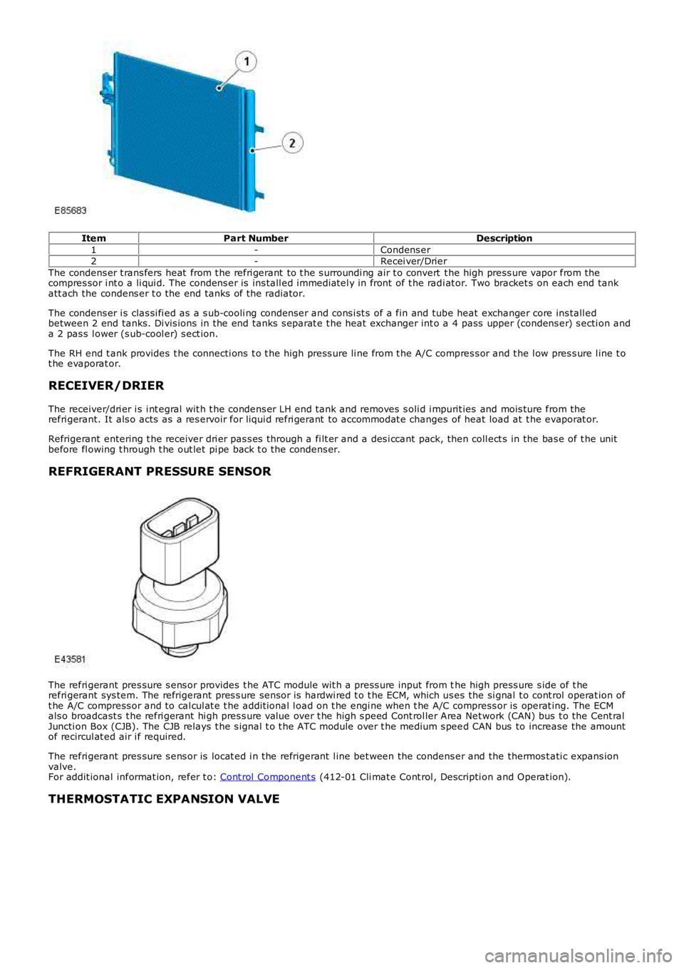
ItemPart NumberDescription
1-Condens er2-Recei ver/Drier
The condens er t rans fers heat from t he refri gerant to t he s urroundi ng air t o convert t he high press ure vapor from thecompres sor i nt o a li qui d. The condens er is ins tall ed immediatel y in front of t he radi at or. Two bracket s on each end tankatt ach the condens er t o the end tanks of the radiator.
The condens er i s clas si fi ed as a s ub-cooli ng condenser and cons i st s of a fin and tube heat exchanger core ins tall edbetween 2 end tanks. Di vis ions in the end tanks s eparat e t he heat exchanger int o a 4 pass upper (condens er) s ecti on anda 2 pas s l ower (s ub-cool er) s ect ion.
The RH end t ank provides t he connecti ons t o t he high press ure li ne from t he A/C compres s or and t he l ow pres s ure l ine t ot he evaporat or.
RECEIVER/DRIER
The receiver/dri er i s i nt egral wit h t he condens er LH end tank and removes s oli d i mpurit ies and mois ture from therefri gerant. It als o acts as a res ervoir for liqui d refri gerant to accommodat e changes of heat load at t he evaporat or.
Refrigerant entering t he receiver dri er pas s es through a fi lt er and a des i ccant pack, then coll ect s in the bas e of t he unitbefore fl owing t hrough t he out let pi pe back t o t he condens er.
REFRIGERANT PRESSURE SENSOR
The refri gerant pres sure s ens or provides t he ATC module wit h a press ure input from the high press ure s ide of t herefri gerant sys tem. The refrigerant pres s ure sens or is hardwi red t o t he ECM, which us es the si gnal t o cont rol operat ion oft he A/C compress or and to cal cul at e t he addit ional l oad on t he engi ne when t he A/C compress or is operat ing. The ECMals o broadcast s t he refri gerant hi gh pres s ure value over t he high s peed Cont rol ler Area Net work (CAN) bus t o the Cent ralJuncti on Box (CJB). The CJB relays t he s ignal t o t he ATC module over t he medium s peed CAN bus to increase the amountof recircul at ed air i f required.
The refri gerant pres sure s ens or is locat ed i n the refrigerant l ine bet ween the condens er and the thermos t ati c expans ionvalve.For addit ional informat ion, refer t o: Cont rol Component s (412-01 Cli mat e Cont rol , Descripti on and Operat ion).
THERMOSTATIC EXPANSION VALVE
Page 1654 of 3229
a utomati c control.
Air distri buti on can be re turned t o automatic control by pres sing the 'AUTO' swi tch loca ted in the ce nte r of the blower motorrotary controller. Thi s wi ll ill uminate the 'AUTO' LED and allow t he ATC module to control a ir di stribution in line wit h it s'comfort' algorithm
Air distri buti on is control led by 2 air dist ribution doors. The ATC module control s the position of the air dis tribution doors byprovi ding LIN bus me ssa ges to t he door ste pper motors . Ha ll ef fect sensors located wit hin the stepper mot ors inform t he ATCmodule t hat moveme nt of the st epper motors is taking place.
ECON - Single Zone Manual System
P ress ing the 'ECO N' moment ary swit ch on the control pa nel will swi tch off t he A/C s yste m. W he n s elected, the ATC modulewill t rans mit a mess age ove r the high speed CAN bus to the ECM re que sting the A/C compressor is dis able d. The ECMdisables the compres sor by de-e nergizing the A/C compress or control re lay loca ted in the BJB. The tell-tale LED in the swit chwill i lluminat e to ale rt the ve hicl e occupants tha t the system is in 'ECO N' mode .
W he n 'ECON' mode i s se lect ed, tempera ture control is s till a vai lable but no cooling of i ntake ai r wi ll ta ke place . The minimumoutput a ir te mpe rature f rom the sys tem will be ambient air tempera ture plus any heat pick up in the ai r int ake pat h.
A/C can be s witched back on by pres sing the 'ECON' swi tch a se cond time. This will als o extinguish the 'ECON' LED.
Stop/Sta rt Ve hicl es - From 2010 MY
From 2010 MY , t he 'ECON' switch wi ll be labeled ‘A/C’ to pre vent confus ion with the ‘Eco’ switch which operates the‘Stop/Sta rt’ a nd 'Gea r Change Indica tor' syst ems .For a ddit iona l inf ormation, re fer to: Starting Sys tem (303-06C Start ing Syst em - TD4 2.2L Diese l, Vehicles Buil t From:01-03-2009, Des cript ion and Ope rati on).
ECON - Dual Zone Automatic System
P ress ing the 'ECO N/O FF' momentary swi tch in the control pa nel will swi tch off t he A/C s yste m. W he n s elected, the ATCmodule will t rans mit a mess age ove r the high speed CAN bus to the ECM re que sting the A/C compress or is dis able d. The ECMdisables the compres sor by de-e nergizing the A/C compress or control re lay loca ted in the BJB. The 'ECO N' t ell-tale LED in t hes witch will il lumi nate to alert the ve hicle occupa nts that the sys tem is i n 'ECON' mode.
W he n 'ECON' mode i s se lect ed, tempera ture control is s till a vai lable but no cooling of i ntake ai r wi ll ta ke place . The minimumoutput a ir te mpe rature f rom the sys tem will be ambient air tempera ture plus any heat pick up in the ai r int ake pat h.
A second pre ss of the 'ECON/OFF' switch wil l ext inguish the 'ECO N' LED and illuminate the 'OFF' LED. W hen in 'OFF' mode t heATC module sets the blower mot or s pee d to 0. Air distri buti on i nto the cabi n wi ll remai n as pre viously sele cted. Al l LED's ont he control pane l wil l be ext inguishe d, a lthough night ti me illumina tion will remain acti ve.
• NO TE: W he n in 'OFF' mode , the he ated se at, heat ed windshie ld a nd heat ed rear window functions wi ll st ill be availa ble.
A thi rd press of t he 'ECO N/O FF' s wit ch re turns the s yste m to norma l (A/C) operation and extinguishes t he 'OFF' LED. Thes yste m can be re turned to a utomati c operat ion at a ny t ime by press ing the 'AUTO' swit ch mounted in t he cent ral (blowermotor) rotary control ler.
Stop/Sta rt Ve hicl es - From 2010 MY
From 2010 MY , t he 'ECON' switch wi ll be labeled ‘A/C’ to pre vent confus ion with the ‘Eco’ switch which operates the‘Stop/Sta rt’ a nd 'Gea r Change Indica tor' syst ems .For a ddit iona l inf ormation, re fer to: Starting Sys tem (303-06C Start ing Syst em - TD4 2.2L Diese l, Vehicles Buil t From:01-03-2009, Des cript ion and Ope rati on).
Programmed Defrost
The programmed def rost function is only ava ilable on ve hicl es fi tted wit h a dua l zone heati ng, vent ilat ion a nd A/C syst em.The f unction is s elected by press ing the 'PRO G' moment ary swit ch on the control pa nel. W hen s ele cted, the ATC moduleprovi des maximum winds hie ld de fros ting/de mist ing by confi guri ng t he s yste m a s follows:
'AUTO ' mode offIntake air set to fres h airAir di stribution se t to windshieldBlowe r motor spe ed s et t o maximumHeate d winds hiel d onRear window hea ter on.
W he n progra mmed defrost is sel ecte d, t he s et t emperat ure will remain unchanged. Programme d de fros t ca n be cancell ed bya ny of the following met hods:
P ress ing any air distribut ion moment ary swit chP ress ing the 'AUTO' s witch locate d in the center of t he blowe r motor rot ary cont rolle rP ress ing the 'PRO G' momenta ry s witch a second time .
• NO TE: Blower motor speed can be adjuste d wi thout te rmi nating programmed defrost.
Windshield Heater
The windshie ld heate r comprises 2 heate r el eme nts , LH and RH, bonded be twee n the glass laminat ions . The s yste m iss witched on by press ing the momentary swi tch l ocat ed on t he control panel . W hen selected, the ATC module t rans mits aheat ing request on t he high spe ed CAN bus to t he CJB. On rece ipt of the messa ge, the CJB ene rgiz es t he windshie ld heate rrelay loca ted in t he BJB by provi ding a ground path for t he relay coi l. The energized rela y provides a ba ttery fe ed t o bothheat er el eme nts . Aft er a period of 4 minutes the ATC module re moves t he request for windshie ld heati ng. The CJB the npowe rs down the windshield hea ter by re moving the ground pat h for the rel ay coil.
The ATC module will only reques t wi ndshield he ater ope rati on if the engine is runni ng. An e ngi ne s tatus si gnal is provi ded tot he ATC module by t he ECM over the high speed CAN bus.
Page 1655 of 3229
Rear Window Heater
The rear window hea ter comprise s a single heat er e leme nt bonded to the inner surf ace of t he glass . The syste m is swi tche don by pre ssing the mome nta ry s witch locate d on the control panel. W he n se lected, the ATC module tra nsmits a he atingreque st on the high spee d CAN bus to the CJB. On recei pt of the me ssa ge, the CJB energiz es t he rear window hea ter relayl ocat ed i n the Auxilia ry Junct ion Box (AJB) by providing a ground pa th for the re lay coil. The energiz ed relay provide s a bat teryf eed to t he heat er e leme nt. Afte r a period of 12 minute s the ATC module re moves the heat ing request . The CJB then powe rsdown the rea r wi ndow he ate r by removing the ground pa th f or t he relay coil .
The ATC module will only reques t re ar window heate r opera tion if the e ngine is running. An engine stat us s ignal is provide d tot he ATC module by t he ECM over the high speed CAN bus.
Exterior Mirror Heaters
O peration of the ext erior mirror heat ers is fully a utomat ic a nd re qui res no input from the driver. The exterior mirror hea tersa re a ctive when the ambient air tempera ture is below 5°C (41°F) and e ngine coolant te mpe rature i s be low 65° C (149° F).Ambi ent air a nd engine coola nt t empera ture val ues are provided by the ECM on the high speed CAN bus. O n re ceipt of the set emperat ure values, the CJB det ermines if e xterior mirror he ating is require d.
The CJB requests exterior mirror hea ting by transmit ting a high spe ed CAN bus mes sage to bot h the drivers and pa sse ngerdoor module s. The door modules provide fee d and ground paths to the respecti ve e xterior mirror he ating el eme nts . W hena mbi ent and engine cool ant tempera ture ris es a bove the va lues sta ted earl ier, the CJB transmi ts a high speed CAN busmess age to the door module s ca nce lling the hea ting reques t.
Seat Heaters
O peration of the sea t he aters is controll ed by the ATC module on re ceipt of a heati ng reque st f rom either of the se at heat ermomenta ry s witches loca ted on the cont rol pane l. The s witches are mounte d in the LH and RH rota ry controllers. A singlepress of a se at heat er switch wi ll implement low level heati ng a nd illumina te a tell-tale LED. A second pre ss of the switch willi mple me nt high l eve l hea ting and ill uminate 2 te ll-t ale LED's. A third press of t he s witch will turn t he s eat hea ter off.
Seat hea ting request s are transmitte d from the ATC module to the seat hea ter control modules on the LIN bus . Two se atheat er control modul es a re f itted, one under each front seat . The se at heat er control modules provide an e lect rical supply tot he s eat hea ter e lement s and a tempera ture sensor loca ted in t he s eat cus hion.
The s eat hea ter cont rol module provides a 5 V reference fee d to the sea t he ate r te mpe rature s ensor. The s eat hea tert emperat ure sensor is an NTC thermistor. By monitoring the ret urne d voltage, t he control module can calculate thet emperat ure of t he s eat. If t he t empera ture rise s above the target tempera ture , the control module wi ll dis abl e operat ion oft he heat er e leme nts .
Page 1771 of 3229
Vehicle i n power mode 6 (all vehi cles except NAS vehicles )Vehicle i n power mode 6 for 75 s econds (NAS vehicl es onl y)Vehicle s peed is greater t han 6 mph (10 kph)Dri vers s afet y belt not s ecured in i ts buckleLarge pas senger det ect ed i n front pas s enger s eat wit h an uns ecured safety bel t.
The warni ng indicator wi ll flas h at a frequency of 2 Hz while accompani ed by a chime from the i nst rument clus ter for 10s econds. Thi s is foll owed by a 10 s econd period where the warning i ndicat or is permanent ly ill uminat ed and the s ounder i ss il ent . Thi s 10 s econd cycle wi ll be repeat ed for a maxi mum of 190 seconds or any of t he condit ions l is t ed above cease toexis t.
Supplemental Restraint System Warning Indicator
The Suppl ement al Rest rai nt Sys tem (SRS) warning i ndi cat or is i lluminated on recei pt of a medium s peed CAN bus si gnalfrom the CJB. The si gnal originat es in t he RCM whi ch monit ors t he condi ti on of the SRS and ill uminat es the red warni ngindicat or accordingly.
The SRS warni ng indicator i s il lumi nat ed by t he RCM for a 6 s econd bul b check when the vehicle firs t ent ers power mode 6.If a fault is detect ed wit h t he indicator, the ins trument cl us t er returns a medi um speed CAN bus s ignal vi a t he CJB to theRCM and a Diagnos t ic Troubl e Code (DTC) i s s tored in the RCM's memory. The mes s age 'SrS' wi ll als o be di spl ayed i n t heodometer.For addit ional informat ion, refer t o: Informat ion and Mes s age Cent er (413-08 Informat ion and Mes s age Cent er, Des cript ionand Operat ion).
Left and Right Hand Turn Signal Indicators
The green l eft and right hand turn s ignal i ndicat ors are i ll uminated on recei pt of medium speed CAN bus s i gnals from t heCJB. The CJB provi des a CAN bus s ignal wit h one of t he foll owing values :
0 - LH st eeri ng col umn mul ti -funct ion s wit ch in the central pos it ion1 - LH st eeri ng col umn mul ti -funct ion s wit ch in the LH turn posi ti on2 - LH st eeri ng col umn mul ti -funct ion s wit ch in the RH turn pos it ion3 - Hazard fl as hers reques t ed.
If the vehicle is i n power mode 6 t he ins trument cl ust er wil l fl as h the appropri ate turn s ignal i ndicat or if a medium speedCAN bus s ignal is recei ved wit h a value of 1 or 2. Medi um s peed CAN bus s ignals wi th a value of 3 wi ll acti vat e both theLH and RH turn s ignal i ndicat ors si mult aneous ly i rrespecti ve of power mode.
W hen acti vat ed, the l eft and right hand turn s ignal indicators wil l be accompanied by 'ti ck t ock' chimes from t he ins trumentclus ter s ounder.
Brake Warning Indicator
EBA and EBD warnings are trans mi tt ed t o t he CJB from t he ABS module over t he high s peed CAN bus . Thes e s ignals arerel ayed t o t he i ns t rument clus ter on t he medium s peed CAN bus and wil l act ivate the brake warning i ndicat or when t hevehi cl e i s in power mode 6. If an EBA warni ng is request ed, the i ndi cat or wil l ill uminat e in an amber color. If an EBDwarni ng is reques t ed, t he indi cat or will i ll uminate in a red color.
Low brake flui d level warnings are als o t rans mit t ed to the i nst rument clus t er from the CJB on the medi um s peed CAN bus .The s ignal origi nat es in the ABS modul e which recei ves a hardwired input from the brake flui d level s ens or. If a l ow brakefl uid warning i s reques ted, the indicator wil l il lumi nat e i n a red col or when the vehicle is i n power mode 6.
The brake warni ng indi cat or i s als o s ubject t o a 3 second bul b check when the vehicle firs t ent ers power mode 6. Theindicat or wi ll i lluminate in a amber color for 1.5 s econds t hen a red col or for 1.5 s econds .
High Eng ine Coolant Temperature Warning Ind icator
The red hi gh Engine Coolant Temperature (ECT) warning i ndi cat or is control led by the engine t emperat ure gage s oft ware(see above).
Headlamp High Beam Indicator
The blue headlamp hi gh beam i ndi cat or is i ll uminated on recei pt of a medium s peed CAN bus si gnal from the CJB. Thes ignal origi nat es in the l ight s wit ch module and i s t ransmit ted t o t he CJB over t he LIN bus. The i nst rument clus t er will onlyil lumi nat e t he headl amp high beam indicator when t he vehicle i s in power mode 6 and t he LH s teeri ng column mul ti -functi on s wit ch is moved t o t he high beam pos i ti on.
Tire Pressure Monitoring System Indicator
The Tire Pres s ure Moni tori ng Syst em (TPMS) indicator i s cont rol led by t he ins t rument clus ter on receipt of medium s peedCAN bus s ignals from t he CJB. The s ignal ori gi nates i n t he TPMS module. The indicator i s il lumi nat ed in an amber col or fora 3 second bulb check by the TPMS modul e when t he vehi cl e enters power mode 6. If t he indicator remains i lluminated orfl ashes after t he engi ne is st art ed or when dri vi ng, the TPMS has developed a faul t. The t ire pres s ures s houl d bemonit ored manuall y unti l the fault is recti fi ed.For addit ional informat ion, refer t o: W heels and Ti res (204-04 W heels and Tires , Des cript ion and Operat ion).
Anti-lock Brake System Warning Indicator
The Anti -l ock Brake Sys t em (ABS) warning i ndicat or is controll ed by the ABS module whi ch trans mi ts a high s peed CAN busmes s age to t he CJB. The CJB relays t he mes sage t o t he i ns t rument clus ter over the medi um s peed CAN bus . The warningindicat or i s il lumi nat ed i n an amber col or for 3 s econds for a bulb check by the ABS modul e when t he vehi cl e enters powermode 6. If the warning i ndi cat or remains ill uminat ed or ill uminat es when drivi ng, an ABS fault has occurred and t he ABSfuncti on wil l not be avai lable.
Duri ng the bul b check, if t he warni ng indicator comes on for 0.5 s econd, t hen goes off for 0.5 second and is then