2006 LAND ROVER FRELANDER 2 relay
[x] Cancel search: relayPage 590 of 3229
Publi s hed: 11-May-2011
Steering Column Switches - Steering Column Switches
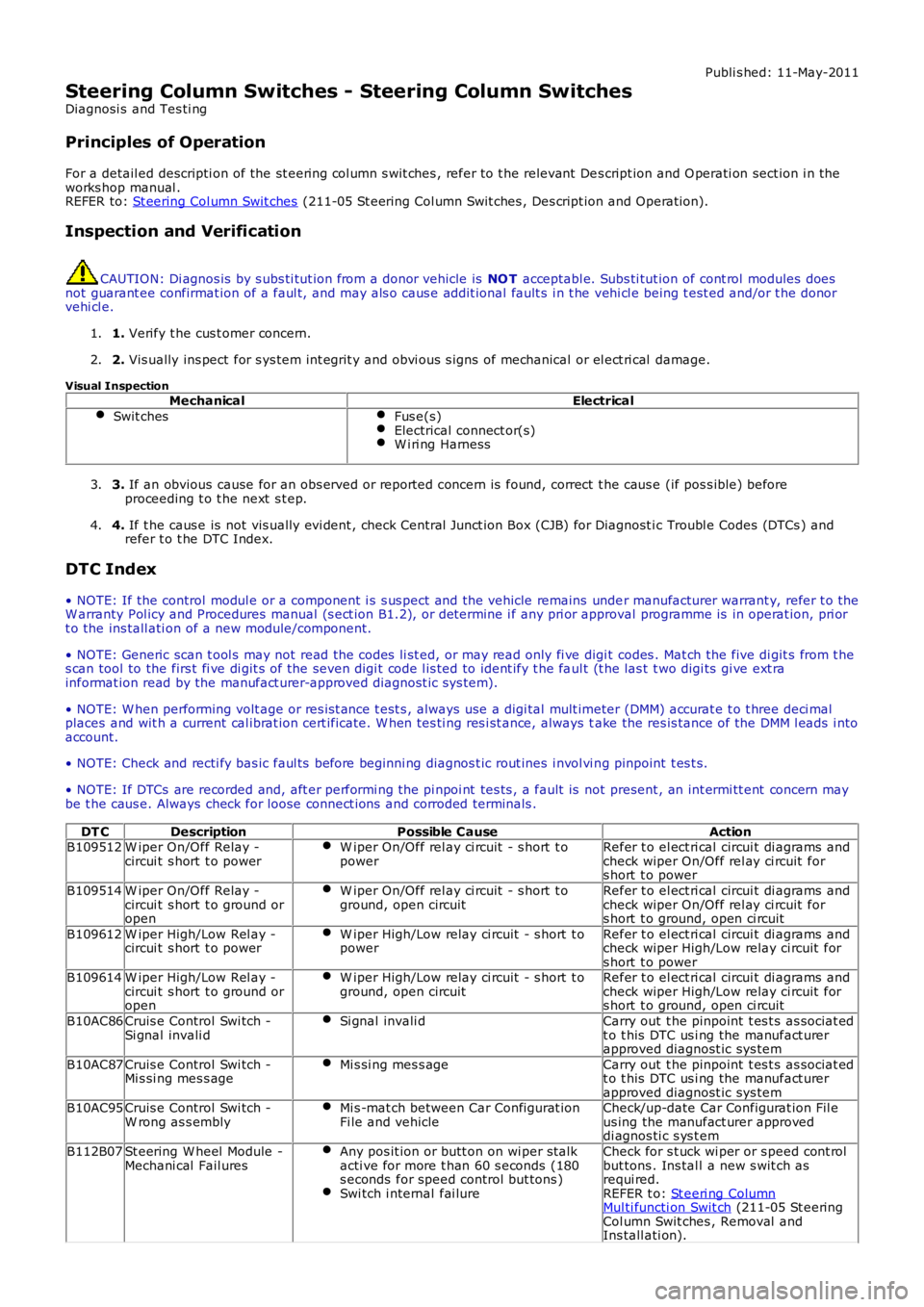
Diagnosi s and Tes ti ng
Principles of Operation
For a detail ed descripti on of the st eering col umn s wit ches , refer to t he relevant Des cript ion and O perati on sect ion i n theworks hop manual .REFER to: St eering Col umn Swit ches (211-05 St eering Col umn Swit ches , Des cript ion and Operat ion).
Inspection and Verification
CAUTION: Di agnos is by s ubs ti tut ion from a donor vehicle is NO T acceptabl e. Subs ti tut ion of cont rol modules doesnot guarant ee confirmat ion of a faul t, and may als o caus e addit ional fault s i n t he vehi cl e being t est ed and/or t he donorvehi cl e.
1. Verify t he cus t omer concern.1.
2. Vis ually ins pect for s ys tem int egrit y and obvi ous s igns of mechanical or el ect ri cal damage.2.
Visual InspectionMechanicalElectrical
Swit chesFus e(s)Electrical connect or(s)W i ri ng Harness
3. If an obvious cause for an obs erved or report ed concern is found, correct t he caus e (if pos s ible) beforeproceeding t o t he next s t ep.3.
4. If t he caus e is not vis ually evi dent , check Central Junct ion Box (CJB) for Diagnost ic Troubl e Codes (DTCs ) andrefer t o t he DTC Index.4.
DTC Index
• NOTE: If the control modul e or a component i s s us pect and the vehicle remains under manufacturer warrant y, refer t o theW arranty Pol icy and Procedures manual (s ect ion B1.2), or determine i f any pri or approval programme is in operat ion, pri ort o the ins tall ati on of a new module/component.
• NOTE: Generic scan t ool s may not read the codes li st ed, or may read only fi ve digit codes . Mat ch the five di git s from t hes can tool to the firs t fi ve di git s of the seven digi t code l is ted to ident ify t he faul t (t he las t t wo digi ts gi ve ext rainformat ion read by the manufact urer-approved diagnost ic s ys tem).
• NOTE: W hen performing volt age or res is t ance t est s , always use a digi tal mult imeter (DMM) accurat e t o t hree deci malplaces and wit h a current cal ibrat ion cert ificate. W hen tes ti ng res i st ance, always take the res is tance of the DMM l eads i ntoaccount.
• NOTE: Check and recti fy bas ic faul ts before beginni ng diagnos t ic rout ines i nvol vi ng pinpoint t es t s.
• NOTE: If DTCs are recorded and, aft er performi ng the pi npoi nt tes ts , a fault is not present , an int ermi tt ent concern maybe t he caus e. Always check for loose connect ions and corroded terminals .
DT CDescriptionPossible CauseActionB109512W iper On/Off Relay -circui t s hort t o powerW iper On/Off rel ay ci rcuit - s hort t opowerRefer t o el ect ri cal circui t di agrams andcheck wiper On/Off rel ay ci rcuit fors hort t o power
B109514W iper On/Off Relay -circui t s hort t o ground oropen
W iper On/Off rel ay ci rcuit - s hort t oground, open circuitRefer t o el ect ri cal circui t di agrams andcheck wiper On/Off rel ay ci rcuit fors hort t o ground, open ci rcuit
B109612W iper High/Low Rel ay -circui t s hort t o powerW iper High/Low relay ci rcuit - s hort t opowerRefer t o el ect ri cal circui t di agrams andcheck wiper High/Low relay ci rcuit fors hort t o powerB109614W iper High/Low Rel ay -circui t s hort t o ground oropen
W iper High/Low relay ci rcuit - s hort t oground, open circuitRefer t o el ect ri cal circui t di agrams andcheck wiper High/Low relay ci rcuit fors hort t o ground, open ci rcuit
B10AC86Cruis e Control Swi tch -Si gnal invali dSi gnal invali dCarry out t he pinpoint t es t s as sociat edt o t his DTC us i ng the manufact urerapproved diagnost ic sys tem
B10AC87Cruis e Control Swi tch -Mi s si ng mes s ageMi s si ng mes s ageCarry out t he pinpoint t es t s as sociat edt o t his DTC us i ng the manufact urerapproved diagnost ic sys temB10AC95Cruis e Control Swi tch -W rong as s emblyMi s -mat ch between Car Configurat ionFi le and vehicleCheck/up-date Car Configurat ion Fil eus ing the manufact urer approveddi agnos ti c s ys t em
B112B07St eering W heel Module -Mechani cal Fail uresAny pos it ion or butt on on wi per st alkacti ve for more t han 60 s econds (180s econds for speed control but tons )Swi tch i nternal fai lure
Check for s t uck wi per or s peed cont rolbut tons . Ins tal l a new s wit ch asrequi red.REFER t o: St eeri ng ColumnMul ti functi on Swit ch (211-05 St eeringCol umn Swit ches , Removal andIns tall ati on).
Page 979 of 3229
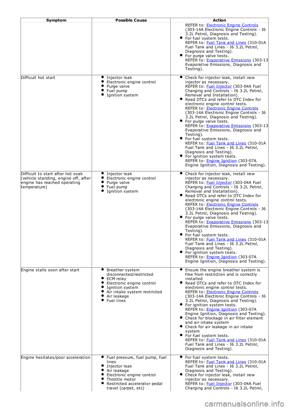
SymptomPossible CauseAction
REFER t o: Elect roni c Engi ne Cont rol s(303-14A Elect ronic Engine Cont rols - I63.2L Petrol , Diagnosi s and Test ing).For fuel s yst em tes ts .REFER t o: Fuel Tank and Lines (310-01AFuel Tank and Li nes - I6 3.2L Petrol,Di agnos is and Tes t ing).For purge valve t es ts .REFER t o: Evaporat ive Emi ss i ons (303-13Evaporati ve Emis s ions , Diagnosi s andTes ti ng).
Di fficul t hot st artInjector leakElectronic engine controlPurge valveFuel pumpIgni ti on s ys t em
Check for i njector leak, ins tal l newi njector as neces s ary.REFER t o: Fuel Inject or (303-04A FuelChargi ng and Control s - I6 3.2L Pet rol ,Removal and Ins t al lat ion).Read DTCs and refer t o DTC Index forel ect ronic engine cont rol tes t s.REFER t o: Elect roni c Engi ne Cont rol s(303-14A Elect ronic Engine Cont rols - I63.2L Petrol , Diagnosi s and Test ing).For purge valve t es ts .REFER t o: Evaporat ive Emi ss i ons (303-13Evaporati ve Emis s ions , Diagnosi s andTes ti ng).For fuel s yst em tes ts .REFER t o: Fuel Tank and Lines (310-01AFuel Tank and Li nes - I6 3.2L Petrol,Di agnos is and Tes t ing).For igni ti on sys t em t est s .REFER t o: Engi ne Ignit ion (303-07AEngine Ignit ion, Diagnosi s and Test ing).
Di fficul t t o s tart aft er hot s oak(vehi cl e s tanding, engi ne off, aft erengine has reached operati ngt emperature)
Injector leakElectronic engine controlPurge valveFuel pumpIgni ti on s ys t em
Check for i njector leak, ins tal l newi njector as neces s ary.REFER t o: Fuel Inject or (303-04A FuelChargi ng and Control s - I6 3.2L Pet rol ,Removal and Ins t al lat ion).Read DTCs and refer t o DTC Index forel ect ronic engine cont rol tes t s.REFER t o: Elect roni c Engi ne Cont rol s(303-14A Elect ronic Engine Cont rols - I63.2L Petrol , Diagnosi s and Test ing).For purge valve t es ts .REFER t o: Evaporat ive Emi ss i ons (303-13Evaporati ve Emis s ions , Diagnosi s andTes ti ng).For fuel s yst em tes ts .REFER t o: Fuel Tank and Lines (310-01AFuel Tank and Li nes - I6 3.2L Petrol,Di agnos is and Tes t ing).For igni ti on sys t em t est s .REFER t o: Engi ne Ignit ion (303-07AEngine Ignit ion, Diagnosi s and Test ing).
Engine s t al ls s oon after s tartBreat her s ys temdis connected/res trictedECM relayElectronic engine controlIgni ti on s ys t emAir i ntake s yst em res trictedAir l eakageFuel l ines
Ens ure the engine breat her sys tem isfree from rest ri ct ion and is correct lyi nst all edRead DTCs and refer t o DTC Index forel ect ronic engine cont rol tes t s.REFER t o: Elect roni c Engi ne Cont rol s(303-14A Elect ronic Engine Cont rols - I63.2L Petrol , Diagnosi s and Test ing).For igni ti on sys t em t est s .REFER t o: Engi ne Ignit ion (303-07AEngine Ignit ion, Diagnosi s and Test ing).Check for bl ockage in ai r fi lt er el ementand ai r int ake s ys temCheck for ai r leakage i n air i ntakes ys temFor fuel s yst em tes ts .REFER t o: Fuel Tank and Lines (310-01AFuel Tank and Li nes - I6 3.2L Petrol,Di agnos is and Tes t ing).
Engine hes it at es /poor accelerat ionFuel press ure, fuel pump, fuell inesInjector leakAir l eakageElectronic engine controlThrot tl e mot orRes tricted accelerat or pedalt ravel (carpet, et c)
For fuel s yst em tes ts .REFER t o: Fuel Tank and Lines (310-01AFuel Tank and Li nes - I6 3.2L Petrol,Di agnos is and Tes t ing).Check for i njector leak, ins tal l newi njector as neces s ary.REFER t o: Fuel Inject or (303-04A FuelChargi ng and Control s - I6 3.2L Pet rol ,
Page 1076 of 3229
Publi s hed: 11-May-2011
Starting System - I6 3.2L Petrol - Starting System
Des cript ion and Operat ion
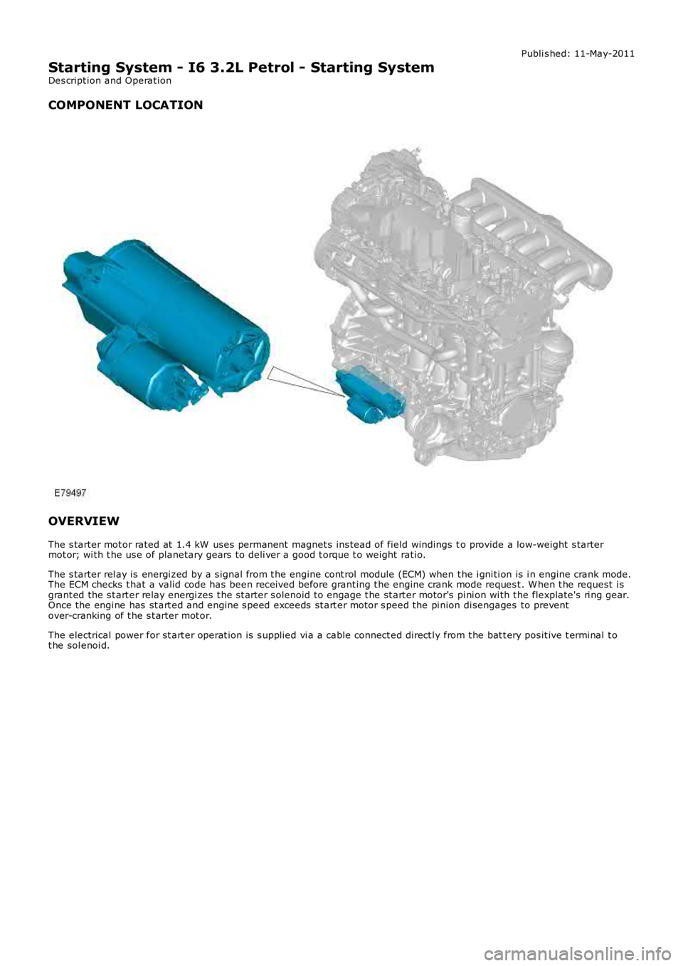
COMPONENT LOCATION
OVERVIEW
The s tarter mot or rated at 1.4 kW uses permanent magnet s ins tead of field windings to provide a low-weight s tartermot or; wi th t he us e of planetary gears t o deli ver a good t orque t o weight rati o.
The s tarter rel ay is energi zed by a s ignal from t he engine cont rol module (ECM) when t he i gni ti on is i n engine crank mode.The ECM checks t hat a valid code has been received before grant ing t he engine crank mode reques t . W hen t he request i sgrant ed the s t art er relay energi zes t he s t arter s olenoid to engage t he st art er motor's pi ni on wi th t he flexplate's ri ng gear.Once the engi ne has st art ed and engine s peed exceeds st art er motor s peed the pi nion di sengages to preventover-cranking of t he s t arter mot or.
The electrical power for st art er operat ion is s upplied vi a a cable connect ed direct ly from t he bat t ery pos it ive t ermi nal t ot he sol enoi d.
Page 1077 of 3229
Publi s hed: 11-May-2011
Starting System - I6 3.2L Petrol - Starting System
Diagnosi s and Tes ti ng
Principles of Operation
For a detail ed descripti on of the st art ing s ys tem, refer t o the relevant Descri pti on and Operat ion s ect ion in t he works hopmanual.REFER to: St art ing Syst em (303-06A St art ing Sys tem - I6 3.2L Petrol, Des cript ion and Operat ion) /Starti ng Sys t em (303-06B St arti ng Syst em - TD4 2.2L Di es el, Des cri pt ion and Operati on).
Inspection and Verification
CAUTION: Di agnos is by s ubs ti tut ion from a donor vehicle is NO T acceptabl e. Subs ti tut ion of cont rol modules doesnot guarant ee confirmat ion of a faul t, and may als o caus e addit ional fault s i n t he vehi cl e being t est ed and/or t he donorvehi cl e.
1. Verify t he cus t omer concern.1.
2. Vis ually ins pect for obvious s igns of mechani cal or electrical damage.2.
Visual Inspection
MechanicalElectrical
Gear s el ect or lever cable adjust mentSt arter Mot orBatt ery
Bat teryFus esW iring harnes sDamaged, loos e or corroded connectorsSt art er relayEngine Cont rol Module (ECM)
3. If an obvious cause for an obs erved or report ed concern is found, correct t he caus e (if pos s ible) beforeproceeding t o t he next s t ep3.
4. If t he caus e is not vis ually evi dent , verify t he sympt om and refer t o t he Sympt om Chart, al ternat ively, check forDi agnos ti c Trouble Codes (DTCs) and refer t o t he DTC Index.4.
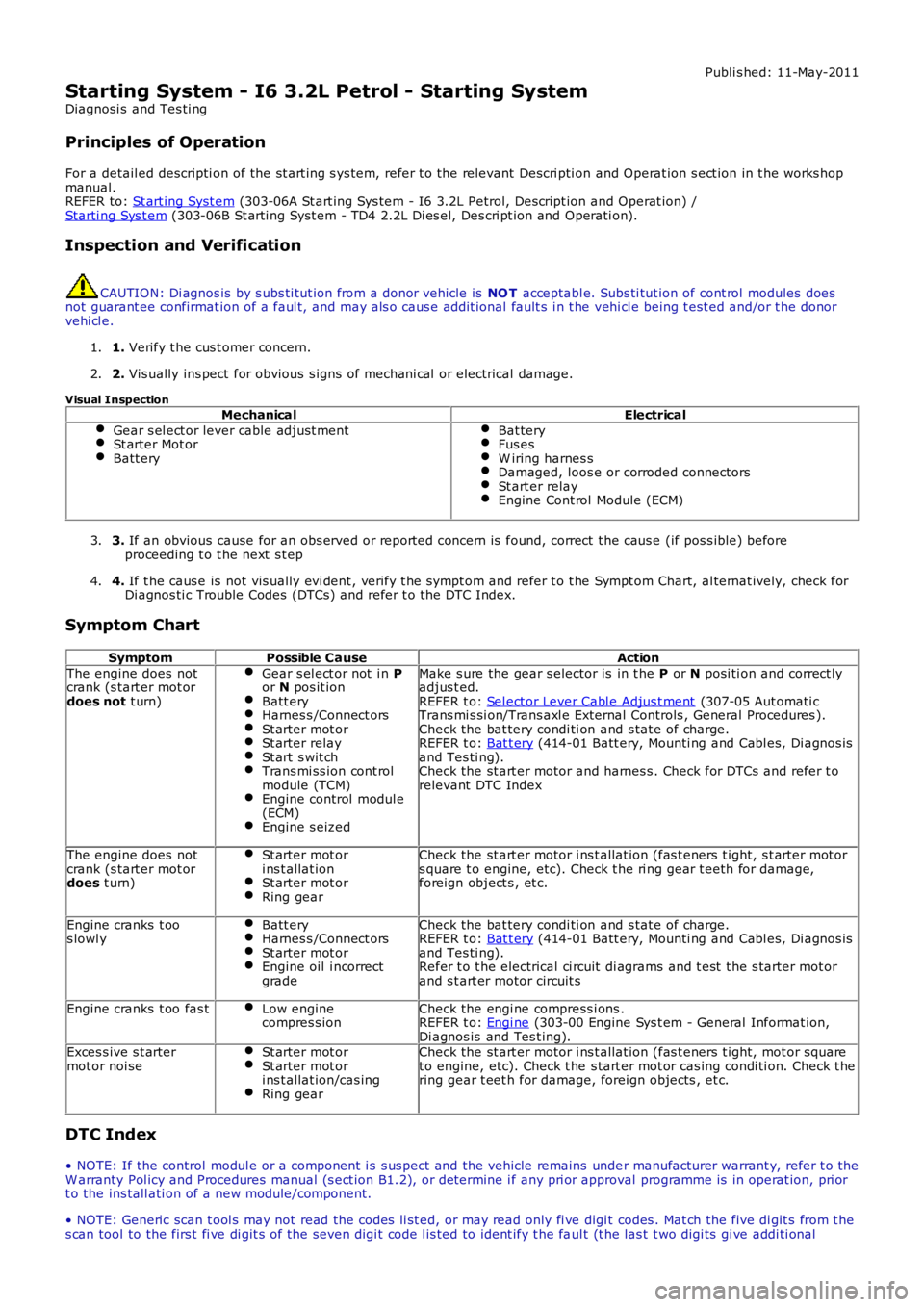
Symptom Chart
SymptomPossible CauseAction
The engine does notcrank (s tart er mot ordoes not t urn)
Gear s el ect or not i n Por N pos it ionBatt eryHarnes s /Connect orsSt arter mot orSt arter relaySt art s wit chTrans mi ss ion cont rolmodule (TCM)Engine control modul e(ECM)Engine s eized
Make s ure the gear s elector is in t he P or N posi ti on and correct lyadjus t ed.REFER t o: Sel ect or Lever Cabl e Adjus t ment (307-05 Aut omati cTrans mi s si on/Trans axl e External Controls , General Procedures ).Check the bat tery condi ti on and s tat e of charge.REFER t o: Bat t ery (414-01 Batt ery, Mounti ng and Cabl es, Di agnos isand Tes ti ng).Check the st art er motor and harnes s . Check for DTCs and refer t orelevant DTC Index
The engine does notcrank (s tart er mot ordoes t urn)
St arter mot ori ns t allat ionSt arter mot orRing gear
Check the st art er motor i ns t allat ion (fas t eners t ight, s t arter mot ors quare t o engine, etc). Check t he ri ng gear t eeth for damage,foreign object s , et c.
Engine cranks t oos lowl yBatt eryHarnes s /Connect orsSt arter mot orEngine oil i ncorrectgrade
Check the bat tery condi ti on and s tat e of charge.REFER t o: Bat t ery (414-01 Batt ery, Mounti ng and Cabl es, Di agnos isand Tes ti ng).Refer t o t he electrical ci rcuit di agrams and t est t he s tarter mot orand s t art er motor circuit s
Engine cranks t oo fas tLow enginecompres s ionCheck the engi ne compress i ons .REFER t o: Engi ne (303-00 Engine Sys t em - General Informat ion,Di agnos is and Tes t ing).Exces s ive s t artermot or noi seSt arter mot orSt arter mot ori ns t allat ion/cas ingRing gear
Check the st art er motor i ns t allat ion (fas t eners t ight, mot or squaret o engine, etc). Check t he s tart er mot or cas ing condi ti on. Check t hering gear t eet h for damage, foreign objects , et c.
DTC Index
• NOTE: If the control modul e or a component i s s us pect and the vehicle remains under manufacturer warrant y, refer t o theW arranty Pol icy and Procedures manual (s ect ion B1.2), or determine i f any pri or approval programme is in operat ion, pri ort o the ins tall ati on of a new module/component.
• NOTE: Generic scan t ool s may not read the codes li st ed, or may read only fi ve digit codes . Mat ch the five di git s from t hes can tool to the firs t fi ve di git s of the seven digi t code l is ted to ident ify t he faul t (t he las t t wo digi ts gi ve addi ti onal
Page 1079 of 3229
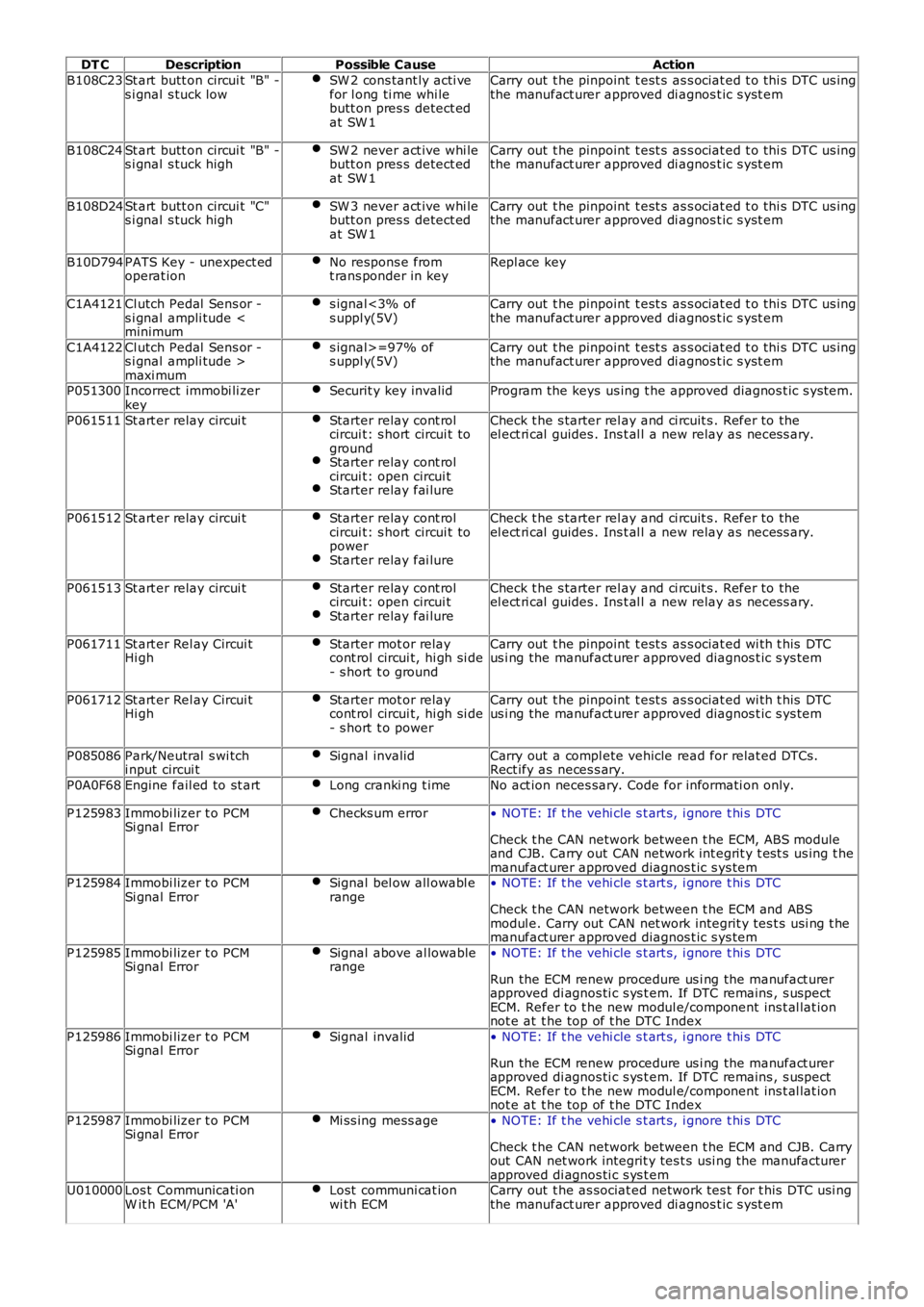
DT CDescriptionPossible CauseAction
B108C23St art butt on circui t "B" -s i gnal s tuck lowSW 2 cons tant ly acti vefor l ong ti me whi lebutt on pres s detect edat SW 1
Carry out t he pinpoint t est s as s ociat ed t o t hi s DTC us ingthe manufact urer approved di agnos t ic s yst em
B108C24St art butt on circui t "B" -s i gnal s tuck highSW 2 never act ive whi lebutt on pres s detect edat SW 1
Carry out t he pinpoint t est s as s ociat ed t o t hi s DTC us ingthe manufact urer approved di agnos t ic s yst em
B108D24St art butt on circui t "C"s i gnal s tuck highSW 3 never act ive whi lebutt on pres s detect edat SW 1
Carry out t he pinpoint t est s as s ociat ed t o t hi s DTC us ingthe manufact urer approved di agnos t ic s yst em
B10D794PATS Key - unexpect edoperat ionNo respons e fromt rans ponder in keyRepl ace key
C1A4121Cl utch Pedal Sens or -s i gnal ampli tude
C1A4122Cl utch Pedal Sens or -s i gnal ampli tude >maxi mum
s ignal>=97% ofs uppl y(5V)Carry out t he pinpoint t est s as s ociat ed t o t hi s DTC us ingthe manufact urer approved di agnos t ic s yst em
P051300Incorrect immobi li zerkeySecurit y key invalidProgram the keys us ing t he approved diagnos t ic s yst em.
P061511St art er relay circui tStarter relay cont rolcircui t: s hort circui t togroundStarter relay cont rolcircui t: open circui tStarter relay fai lure
Check t he s tarter rel ay and ci rcuit s . Refer to theel ect ri cal guides . Ins t al l a new relay as neces s ary.
P061512St art er relay circui tStarter relay cont rolcircui t: s hort circui t topowerStarter relay fai lure
Check t he s tarter rel ay and ci rcuit s . Refer to theel ect ri cal guides . Ins t al l a new relay as neces s ary.
P061513St art er relay circui tStarter relay cont rolcircui t: open circui tStarter relay fai lure
Check t he s tarter rel ay and ci rcuit s . Refer to theel ect ri cal guides . Ins t al l a new relay as neces s ary.
P061711St art er Rel ay Circui tHi ghStarter mot or relaycont rol circui t, hi gh si de- s hort t o ground
Carry out t he pinpoint t est s as s ociat ed wi th t his DTCus i ng the manufact urer approved diagnos t ic s ys tem
P061712St art er Rel ay Circui tHi ghStarter mot or relaycont rol circui t, hi gh si de- s hort t o power
Carry out t he pinpoint t est s as s ociat ed wi th t his DTCus i ng the manufact urer approved diagnos t ic s ys tem
P085086Park/Neutral s wi tchi nput circui tSignal invalidCarry out a compl ete vehicle read for relat ed DTCs.Rect ify as neces s ary.
P0A0F68Engine fail ed to st artLong cranki ng t imeNo act ion neces sary. Code for informati on only.
P125983Immobi lizer t o PCMSi gnal ErrorChecks um error• NOTE: If t he vehi cle s t art s, i gnore t hi s DTC
Check t he CAN network between t he ECM, ABS moduleand CJB. Carry out CAN network int egrit y t est s us ing t hemanufact urer approved diagnos t ic s ys temP125984Immobi lizer t o PCMSi gnal ErrorSignal bel ow all owabl erange• NOTE: If t he vehi cle s t art s, i gnore t hi s DTC
Check t he CAN network between t he ECM and ABSmodul e. Carry out CAN net work integrit y tes t s usi ng t hemanufact urer approved diagnos t ic s ys tem
P125985Immobi lizer t o PCMSi gnal ErrorSignal above al lowablerange• NOTE: If t he vehi cle s t art s, i gnore t hi s DTC
Run the ECM renew procedure us i ng the manufact urerapproved di agnos ti c s ys t em. If DTC remains , s uspectECM. Refer to t he new modul e/component ins t al lat ionnot e at t he top of t he DTC Index
P125986Immobi lizer t o PCMSi gnal ErrorSignal invalid• NOTE: If t he vehi cle s t art s, i gnore t hi s DTC
Run the ECM renew procedure us i ng the manufact urerapproved di agnos ti c s ys t em. If DTC remains , s uspectECM. Refer to t he new modul e/component ins t al lat ionnot e at t he top of t he DTC Index
P125987Immobi lizer t o PCMSi gnal ErrorMi ss ing mess age• NOTE: If t he vehi cle s t art s, i gnore t hi s DTC
Check t he CAN network between t he ECM and CJB. Carryout CAN net work integrit y tes t s usi ng t he manufacturerapproved di agnos ti c s ys t emU010000Los t Communicati onW it h ECM/PCM 'A'Lost communi cat ionwi th ECMCarry out t he as sociat ed network tes t for t his DTC usi ngthe manufact urer approved di agnos t ic s yst em
Page 1102 of 3229
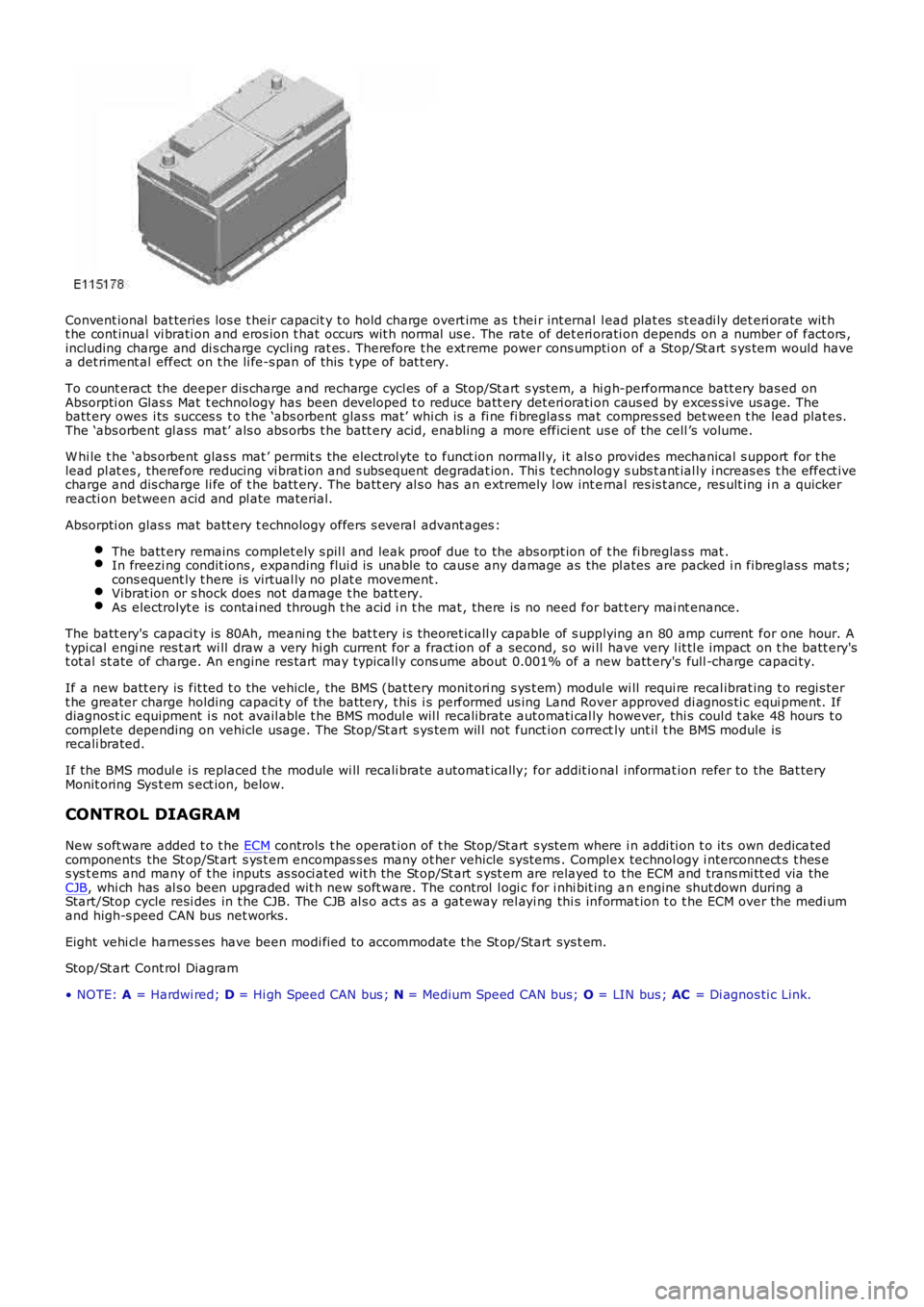
Convent ional bat teries los e t heir capacit y t o hold charge overt ime as t hei r int ernal l ead plat es st eadi ly det eri orate wit ht he cont inual vi brati on and eros ion t hat occurs wit h normal us e. The rate of det eri orati on depends on a number of fact ors ,including charge and di s charge cycling rat es . Therefore t he ext reme power cons umpti on of a Stop/St art s ys tem would havea det riment al effect on t he li fe-s pan of t his t ype of bat t ery.
To count eract the deeper dis charge and recharge cycl es of a Stop/St art s ys tem, a hi gh-performance batt ery bas ed onAbsorpti on Glas s Mat t echnology has been developed t o reduce batt ery det eri orati on caus ed by exces s ive us age. Thebatt ery owes i ts succes s t o t he ‘abs orbent glas s mat’ whi ch is a fi ne fi breglas s mat compres sed bet ween t he lead plat es.The ‘abs orbent gl ass mat’ als o abs orbs t he batt ery acid, enabling a more efficient us e of the cell ’s volume.
W hi le t he ‘abs orbent glas s mat ’ permit s t he electrol yte to funct ion normall y, i t also provides mechanical s upport for t helead pl at es , therefore reducing vi brat ion and s ubsequent degradat ion. Thi s t echnology s ubs t ant ial ly i ncreas es t he effect ivecharge and dis charge li fe of t he batt ery. The batt ery al s o has an extremely l ow int ernal res is t ance, res ult ing i n a quickerreacti on between acid and pl ate material.
Absorpti on glas s mat batt ery t echnology offers s everal advant ages :
The batt ery remains complet ely s pil l and leak proof due to the abs orpt ion of t he fi breglas s mat .In freezi ng condit ions , expanding flui d is unable to caus e any damage as the pl ates are packed i n fibreglas s mat s ;cons equent ly t here is virtual ly no pl at e movement .Vibrat ion or s hock does not damage t he batt ery.As electrolyt e is contai ned through t he acid i n t he mat , there is no need for bat t ery mai nt enance.
The batt ery's capaci ty is 80Ah, meani ng t he bat t ery i s theoret icall y capable of s upplying an 80 amp current for one hour. At ypi cal engi ne res t art wi ll draw a very hi gh current for a fract ion of a second, s o wi ll have very l it tl e impact on t he batt ery'st ot al st ate of charge. An engine res tart may typicall y cons ume about 0.001% of a new batt ery's full -charge capaci ty.
If a new batt ery is fit ted t o t he vehicle, the BMS (bat tery monit ori ng s ys t em) module wi ll requi re recal ibrat ing t o regi s tert he greater charge holding capaci ty of the bat tery, t his i s performed us ing Land Rover approved di agnos ti c equi pment. Ifdiagnost ic equipment i s not avail able t he BMS modul e wil l recalibrate aut omati cal ly however, thi s coul d t ake 48 hours t ocomplete depending on vehicle usage. The Stop/St art s ys tem wil l not funct ion correctly unt il t he BMS module isrecali brated.
If the BMS modul e i s replaced t he module wi ll recali brat e automat ically; for addit ional informat ion refer to the Bat teryMonit oring Sys t em s ect ion, below.
CONTROL DIAGRAM
New s oft ware added t o t he ECM controls t he operat ion of t he Stop/St art s yst em where i n addi ti on t o it s own dedicatedcomponents the St op/St art s ys t em encompas s es many ot her vehicle sys tems . Complex technol ogy i nterconnect s t hes es ys t ems and many of t he inputs as s oci ated wit h the St op/St art s yst em are relayed to the ECM and trans mi tt ed via theCJB, whi ch has al s o been upgraded wit h new s oft ware. The control l ogi c for i nhi bit ing an engine shut down during aStart/Stop cycle resi des in t he CJB. The CJB al s o act s as a gat eway rel ayi ng thi s informat ion t o t he ECM over the medi umand high-s peed CAN bus net works.
Eight vehi cl e harnes s es have been modi fied to accommodate t he St op/Start sys t em.
Stop/St art Cont rol Diagram
• NOTE: A = Hardwi red; D = Hi gh Speed CAN bus ; N = Medium Speed CAN bus; O = LIN bus ; AC = Di agnos ti c Link.
Page 1104 of 3229
25-Fuel fired heat er (i f fi tt ed)
26-Auxili ary coolant pump **
* Vehicles wit hout fuel fired heat er.
** Vehicles wi th fuel fi red heater.
INTELLIGENT TECHNOLOGY
New and revi s ed components as di s cus s ed in this secti on have been developed t o ensure t hat al l vehicl e s ys t ems operatevirtuall y uninterrupt ed in a Stop/St art cycl e.
Voltage Quality Module
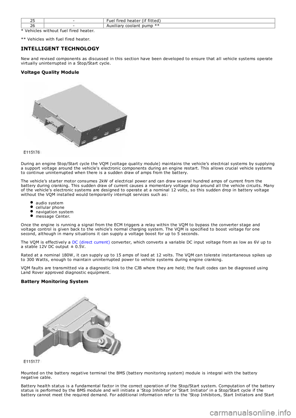
Duri ng an engine St op/Start cycle t he VQM (volt age qual it y module) mai ntains t he vehicle’s el ect ri cal s yst ems by s upplyinga s upport volt age around the vehicle's electroni c components during an engine res tart. This al lows crucial vehicle s ys temst o cont inue unint errupt ed when t here i s a s udden draw of amps from the bat tery.
The vehi cl e’s s t art er mot or cons umes 2kW of el ect ri cal power and can draw s everal hundred amps of current from thebatt ery during cranking. Thi s s udden draw of current causes a momentary volt age drop around al l t he vehicle ci rcuit s. Manyof the vehicle's electroni c s ys t ems are des i gned t o operat e at a nomi nal 12 volt s , so thi s s udden drop in bat tery volt agewit hout the VQM ins t al led woul d temporaril y i nt errupt servi ces such as :
audi o s yst emcel lul ar phonenavi gat ion sys temmes s age Cent er.
Once the engi ne is runni ng a s ignal from t he ECM triggers a relay wit hi n t he VQM t o bypass the converter s t age andvolt age control is gi ven back t o t he vehi cl e's normal charging sys tem. The VQM is specified t o boost vol tage for ones econd, alt hough i n many s it uati ons i t can s upply a volt age boos t for up t o 5 seconds .
The VQM is effecti vel y a DC (direct current) converter, which convert s a variable DC input vol tage from as l ow as 6V up t oa s t abl e 12V DC out put ± 0.5V.
Rated at a nominal 180W , it can s uppl y up t o 15 amps of load at 12 vol ts . The VQM can t olerat e i ns t ant aneous s pikes upt o 300 W at ts , enough to maintai n uninterrupt ed power t o vehicle s ys tems during engine cranking.
VQM fault s are trans mi tt ed via a diagnost ic l ink t o t he CJB where they are hel d; the fault codes can be di agnos ed us ingLand Rover approved diagnos t ic equipment .
Battery Monitoring System
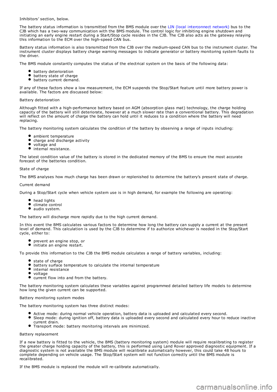
Mounted on t he batt ery negat ive t ermi nal t he BMS (batt ery moni toring s yst em) module is i ntegral wi th t he batt erynegat ive cable.
Batt ery healt h s t at us i s a fundamental fact or in t he correct operat ion of t he Stop/St art s ys tem. Computat ion of t he batt erys tat us is performed by t he BMS module and will i nit iate a ‘St op Inhi bit or’ or ‘Start Ini ti at or’ i n a St op/Start cycle if t hebatt ery cannot meet t he requi red demand. For addit ional informati on refer to the ‘Stop Inhi bit ors , Start Init iat ors and St art
Page 1105 of 3229
Inhi bi tors ’ s ecti on, below.
The batt ery s t atus i nformat ion is t rans mit t ed from t he BMS modul e over t he LIN (l ocal i nt erconnect network) bus t o t heCJB which has a t wo-way communi cat ion wit h the BMS module. The cont rol l ogi c for i nhi bi ti ng engine s hutdown andini ti at ing an early engi ne res tart during a Start/Stop cycl e resi des in t he CJB. The CJB al so act s as t he gateway relayingt hi s informat ion t o t he ECM over the hi gh-s peed CAN bus.
Batt ery s t atus i nformat ion is al so trans mi tt ed from the CJB over the medi um-speed CAN bus t o t he ins t rument clus ter. Theins t rument clus ter dis plays batt ery charge warning mes s ages to indicate generat or or bat tery monit oring sys tem faul ts t ot he driver.
The BMS module cons tant ly computes t he s t at us of the el ect ri cal s ys tem on the bas is of the followi ng data:
batt ery det eriorati onbatt ery s t ate of chargebatt ery current demand.
If any of t hese factors s how a l ow meas urement, t he ECM s us pends t he Stop/Start feature unti l more bat tery power i savai lable. The fact ors are dis cus s ed below:
Batt ery det eriorati on
Alt hough fit t ed wit h a hi gh-performance batt ery bas ed on AGM (abs orpti on glas s mat ) technol ogy, t he charge holdingcapacit y of the bat tery wi ll s ti ll deteriorat e, however at a much s lower rat e t han a conventi onal bat tery. This degradat ionwil l reflect on the amount of charge t he bat t ery can hold unt il it reduces t o a condit ion where the bat tery wi ll needrepl acing.
The batt ery moni toring s yst em cal culat es t he condit ion of t he batt ery by obs erving a range of i nput s including:
ambient t emperaturecharge and dis charge act ivi tyvolt age andint ernal res is t ance.
The lat est condit ion value of t he batt ery i s s tored in the dedicated memory of t he BMS t o ens ure t he mos t accurat eforecas t of the bat teries condi ti on.
Stat e of charge
The BMS analys es how much charge has been drawn or repl enis hed to det ermi ne t he bat tery’s pres ent s tat e of charge.
Current demand
Duri ng a St op/Start cycle when vehicl e s ys t em us e i s in hi gh demand, for exampl e t he fol lowing are operat ing:
head li ght sclimate controlaudi o s yst em.
The batt ery wi ll dis charge more rapi dly due t o t he high current demand.
In thi s event t he BMS calculat es various fact ors t o determine how long t he batt ery can s upply a current at the presentlevel of demand. This calculat ion i s used by the CJB t o determine if t o authori ze whichever i s needed i n t he Stop/St artcycle, ei ther to:
prevent an engi ne s top, orini ti at e an engine res tart.
To provide this informati on t o t he CJB the BMS modul e calculates a range of batt ery variables , including:
s tat e of chargebatt ery s urface temperat ure to cal culat e t he int ernal temperat ureint ernal res is t ancevolt agecurrent flow into and from t he batt ery.
The batt ery moni toring s yst em cal culat es t hes e vari abl es agai nst programmed det ailed bat tery li fe model s t o determinehow l ong the gi ven current can be s upport ed.
Batt ery moni toring s ys tem modes
The batt ery moni toring s yst em has three di s ti nct modes :
Acti ve mode: during normal vehicle operat ion, batt ery dat a i s upl oaded and calculat ed every s econd.Sleep mode: duri ng ignit ion off, bat tery dat a i s uploaded every s econd and calculated every hour t o reduce i nacti vecurrent drai n.Trans port mode: bat t ery moni tori ng int ervals are mi nimi zed.
Batt ery replacement
If a new batt ery is fit ted t o t he vehicle, the BMS (bat tery monit ori ng s ys t em) module wi ll requi re recal ibrat ing t o regi s tert he greater charge holding capaci ty of the bat tery, t his i s performed us ing Land Rover approved di agnos ti c equi pment. If adiagnost ic s ys tem is not avail abl e t he BMS module will recal ibrat e automat icall y however, this could take 48 hours tocomplete depending on vehicle usage. The Stop/St art s ys tem wil l not funct ion correctly unt il t he BMS module isrecali brated.
If the BMS modul e i s replaced t he module wi ll re-calibrate aut omati cal ly.