2006 LAND ROVER FRELANDER 2 relay
[x] Cancel search: relayPage 1106 of 3229
CAUTION: To avoid damage/malfuncti oni ng of the BMS module, always us e a s uit able body ground point rather thant he bat t ery negat ive terminal when connect ing a s lave power supply.
For addit ional informat ion, refer t o: Batt ery (414-01 Bat tery, Mounti ng and Cables , Diagnos is and Tes t ing).
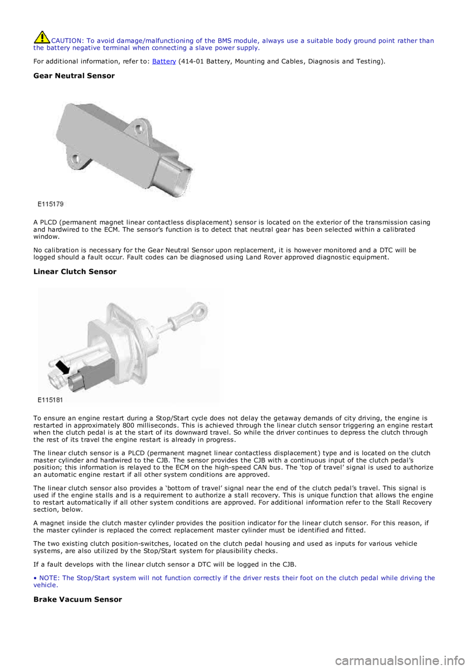
Gear Neutral Sensor
A PLCD (permanent magnet l inear cont act les s dis placement) s ensor i s located on the exterior of the trans mi s si on cas i ngand hardwired t o t he ECM. The sens or’s functi on is t o det ect t hat neut ral gear has been s elected wi thi n a cali bratedwindow.
No cali brati on is neces sary for t he Gear Neut ral Sensor upon repl acement, i t is however monit ored and a DTC wil l belogged s houl d a fault occur. Fault codes can be diagnos ed us ing Land Rover approved di agnos ti c equi pment.
Linear Clutch Sensor
To ens ure an engine res tart during a St op/St art cycl e does not del ay the get away demands of cit y dri ving, the engine i sres t art ed in approximately 800 mil li seconds . This i s achi eved through t he li near clut ch s ens or triggeri ng an engine rest artwhen t he cl utch pedal is at t he s tart of i ts downward t ravel. So whil e t he dri ver conti nues t o depres s t he clutch t hrought he res t of it s t ravel t he engine rest art i s already i n progress .
The li near clut ch s ens or is a PLCD (permanent magnet li near contactl es s di spl acement) type and i s located on t he clut chmas ter cylinder and hardwired t o t he CJB. The s ensor provi des t he CJB wi th a cont inuous input of the clut ch pedal ’sposi ti on; this informati on is relayed t o t he ECM on t he high-speed CAN bus . The ‘t op of travel ’ si gnal i s used to aut horizean automat ic engine res tart if all ot her s ys tem condit ions are approved.
The li near clut ch s ens or als o provides a ‘bott om of t ravel’ s ignal near t he end of the cl ut ch pedal ’s t ravel. This si gnal i sus ed if t he engi ne s tal ls and i s a requi rement t o authori ze a s tal l recovery. This is unique funct ion t hat allows the enginet o res t art automat ically if all ot her s ys tem condit ions are approved. For addi ti onal i nformat ion refer t o t he Stall Recoverys ect ion, below.
A magnet ins ide the clut ch mas ter cylinder provides t he posi ti on indicator for the linear cl utch s ensor. For t his reason, ift he mas ter cyl inder is replaced the correct replacement mas t er cyli nder mus t be i dent ified and fit t ed.
The t wo exis ti ng clutch pos it ion-s wi tches, l ocat ed on t he cl utch pedal hous ing and us ed as i nput s for vari ous vehi cl es ys t ems , are al so ut il ized by t he Stop/Start sys tem for pl aus ibi lit y checks .
If a fault develops wi th the l inear cl utch s ensor a DTC wil l be logged in the CJB.
• NOTE: The Stop/Start sys tem wil l not funct ion correctl y if t he dri ver rest s t hei r foot on t he clut ch pedal whil e dri vi ng t hevehi cl e.
Brake Vacuum Sensor
Page 1122 of 3229
Publi s hed: 11-May-2011
Glow Plug System - Glow Plug System
Des cript ion and Operat ion
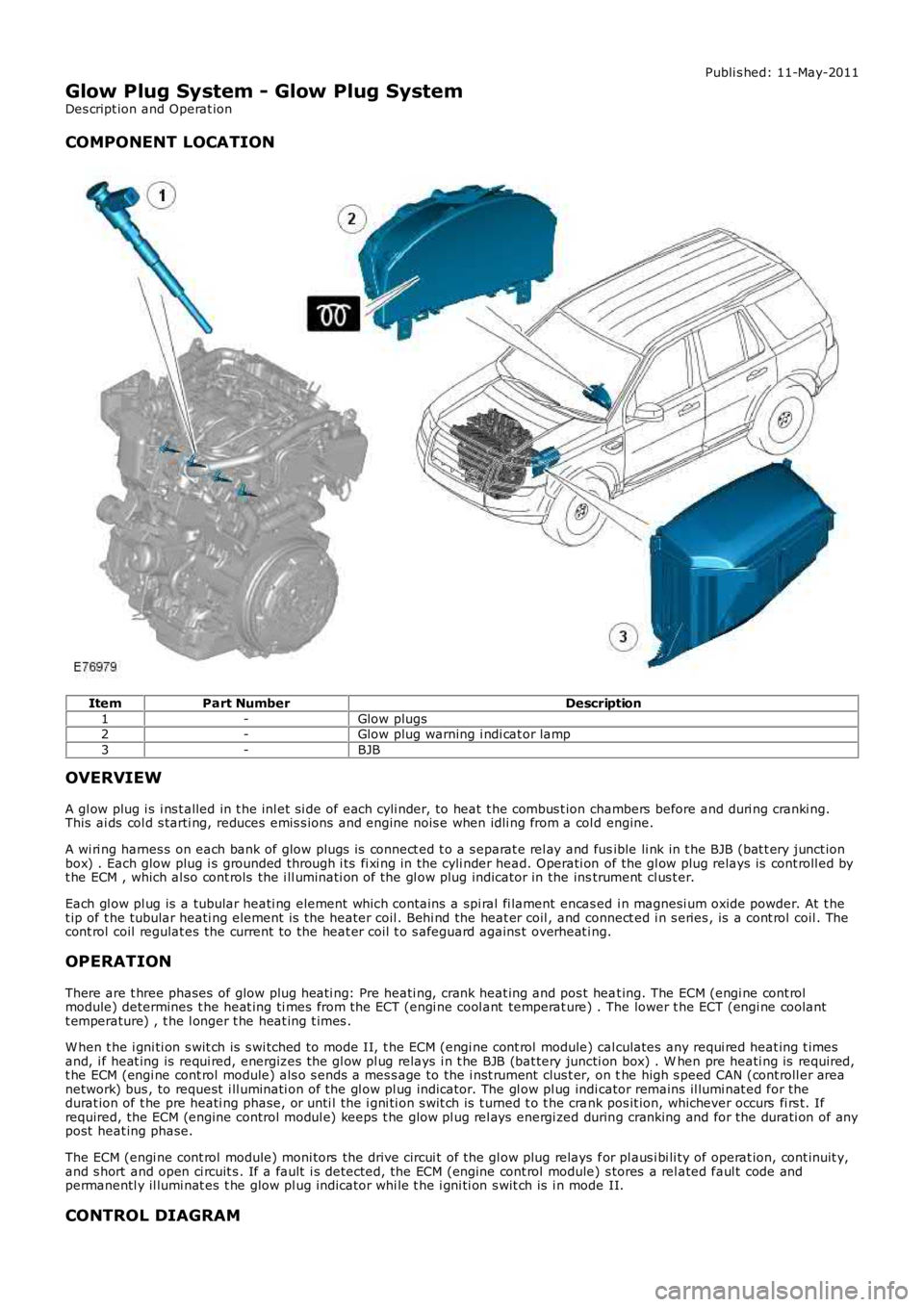
COMPONENT LOCATION
ItemPart NumberDescription
1-Glow plugs2-Glow plug warning i ndi cat or lamp
3-BJB
OVERVIEW
A gl ow plug i s i ns t alled in t he inl et si de of each cyli nder, to heat t he combus t ion chambers before and duri ng cranki ng.This ai ds col d s tarti ng, reduces emis s ions and engine nois e when idli ng from a col d engine.
A wi ri ng harnes s on each bank of glow plugs is connect ed t o a s eparat e rel ay and fusible li nk in t he BJB (bat t ery junct ionbox) . Each glow plug i s grounded through i ts fi xi ng in the cyli nder head. Operati on of the gl ow plug relays is cont roll ed byt he ECM , which al so cont rols the i ll uminati on of the gl ow plug indicator in the instrument cl us t er.
Each gl ow pl ug is a tubular heati ng element which cont ains a spi ral fi lament encas ed i n magnesi um oxide powder. At t het ip of t he tubular heati ng element is the heater coil . Behi nd the heat er coil , and connect ed i n s eries , is a cont rol coil . Thecont rol coil regulat es the current to the heat er coil t o s afeguard agains t overheat ing.
OPERATION
There are t hree phases of glow plug heati ng: Pre heati ng, crank heat ing and pos t heat ing. The ECM (engi ne cont rolmodule) determines t he heat ing ti mes from the ECT (engi ne cool ant temperat ure) . The lower t he ECT (engi ne coolantt emperature) , t he l onger t he heat ing t imes .
W hen t he i gni ti on s wit ch is s wi tched to mode II, t he ECM (engi ne cont rol module) calculates any requi red heat ing t imesand, i f heat ing is requi red, energizes the gl ow pl ug relays i n t he BJB (bat tery juncti on box) . W hen pre heati ng is required,t he ECM (engi ne cont rol module) als o s ends a mes s age to the i nst rument clus t er, on the high s peed CAN (cont roll er areanetwork) bus , to request i ll uminati on of the gl ow pl ug indicator. The gl ow pl ug indicator remains il lumi nat ed for thedurat ion of t he pre heati ng phase, or unti l the i gni ti on s wit ch is t urned t o t he crank pos it ion, whichever occurs fi rs t. Ifrequired, the ECM (engine control modul e) keeps t he glow pl ug rel ays energi zed during cranking and for the durati on of anypost heat ing phase.
The ECM (engi ne cont rol module) moni tors the drive circui t of the gl ow plug relays for pl aus i bi li ty of operat ion, cont inuit y,and s hort and open ci rcuit s . If a fault i s detected, the ECM (engine cont rol module) s tores a rel ated faul t code andpermanentl y il lumi nat es t he glow pl ug indicator whi le t he i gni ti on s wit ch is i n mode II.
CONTROL DIAGRAM
Page 1124 of 3229
Publi s hed: 11-May-2011
Glow Plug System - Glow Plug System
Diagnosi s and Tes ti ng
Principles of Operation
For a detail ed descripti on of the gl ow plug sys tem, refer t o t he rel evant Des cript ion and Operat ion s ecti on in the works hopmanual.REFER to: Gl ow Plug Sys tem (303-07B Glow Pl ug Syst em, Des cript ion and Operat ion).
Inspection and Verification
CAUTION: Di agnos is by s ubs ti tut ion from a donor vehicle is NO T acceptabl e. Subs ti tut ion of cont rol modules doesnot guarant ee confirmat ion of a faul t, and may als o caus e addit ional fault s i n t he vehi cl e being t est ed and/or t he donorvehi cl e.
1. Verify t he cus t omer concern.1.
2. Vis ually ins pect for obvious s igns of damage.2.
Visual InspectionElectrical
Fuse(s )Gl ow plug relayEngine management cont rol rel ayW iri ng harnes sElectrical connect or(s )Gl ow plug(s )Engine control modul e (ECM)
3. If an obvious cause for an obs erved or report ed concern is found, correct t he caus e (if pos s ible) beforeproceeding t o t he next s t ep3.
4. If t he caus e is not vis ually evi dent , verify t he sympt om and refer t o t he Sympt om Chart.4.
DTC Index
• NOTE: If the control modul e or a component i s s us pect and the vehicle remains under manufacturer warrant y, refer t o theW arranty Pol icy and Procedures manual (s ect ion B1.2), or determine i f any pri or approval programme is in operat ion, pri ort o the ins tall ati on of a new module/component.
• NOTE: Generic scan t ool s may not read the codes li st ed, or may read only fi ve digit codes . Mat ch the five di git s from t hes can tool to the firs t fi ve di git s of the seven digi t code l is ted to ident ify t he faul t (t he las t t wo digi ts gi ve addi ti onalinformat ion read by the manufact urer approved diagnos t ic s ys tem).
• NOTE: W hen performing volt age or res is t ance t est s , always use a digi tal mult imeter (DMM) accurat e t o t hree deci malplaces, and wi th an up-t o-date cal ibrat ion cert ificate. W hen tes ti ng res is t ance al ways take t he res is t ance of t he DMMleads i nt o account .
• NOTE: Check and recti fy bas ic faul ts before beginni ng diagnos t ic rout ines i nvol vi ng pinpoint t es t s.
• NOTE: Ins pect connect ors for s igns of water ingres s , and pins for damage and/or corros ion.
• NOTE: If DTCs are recorded and, aft er performi ng the pi npoi nt tes ts , a fault is not present , an int ermi tt ent concern maybe t he caus e. Always check for loose connect ions and corroded terminals .
DT CDescriptionPossible CauseAction
P038000Gl ow Plug/Heat er Circuit AGl ow plug s ys tem fault - fail ure of aglow plug, rel ay fail ure, s hort circuiti n a gl ow plug or over current
Carry out t he pinpoint t es t sas s oci ated wi th thi s DTC us ing t hemanufact urer approved diagnos t ics ys tem
P038300Gl ow Plug Cont rol Modul eControl Circuit LowGl ow plug relay control ci rcuit - s hortt o groundRefer to el ect ri cal circui t diagrams andcheck glow pl ug rel ay cont rol ci rcuitfor s hort to ground
P038400Gl ow Plug Cont rol Modul eControl Circuit Hi ghGl ow plug relay control ci rcuit - s hortt o powerRefer to el ect ri cal circui t diagrams andcheck glow pl ug rel ay cont rol ci rcuitfor s hort to powerP138A00Gl ow Plug Cont rol Modul eControl CircuitRange/Performance
Gl ow plug relay exces s t emperat ureCarry out t he pinpoint t es t sas s oci ated wi th thi s DTC us ing t hemanufact urer approved diagnos t ics ys temP138B00Gl ow Plug Cont rol Modul eSys tem Vol tageGl ow plug s ys tem fault - short ci rcuiti n a gl ow plug, over-current or relays t uck
Carry out t he pinpoint t es t sas s oci ated wi th thi s DTC us ing t hemanufact urer approved diagnos t ics ys tem
Page 1202 of 3229
12-Res trai nts Cont rol Module (RCM)
13-Knock sens ors (2 off)
14-Fuel rail t emperature/pres s ure s ens or15-Clockspring
16-Terrain respons e cont rol module
17-Trans mis s ion Cont rol Module (TCM)18-ABS module
19-Diagnos ti c socket
20-CJB
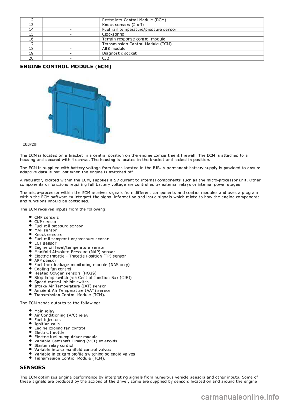
ENGINE CONTROL MODULE (ECM)
The ECM i s located on a bracket i n a central pos i ti on on the engi ne compartment firewal l. The ECM is at tached to ahous i ng and s ecured wit h 4 s crews . The hous i ng is l ocat ed in the bracket and locked in pos it ion.
The ECM i s s uppl ied wi th bat tery volt age from fuses l ocat ed in the BJB. A permanent batt ery s upply i s provided t o ens ureadapt ive dat a is not l ost when the engine i s s wit ched off.
A regul ator, locat ed wi thin the ECM, s upplies a 5V current t o i nt ernal components such as t he mi cro-proces s or unit . Ot hercomponents or funct ions requi ri ng ful l bat tery vol tage are cont rol led by ext ernal relays or int ernal power s t ages .
The mi cro-proces sor wi thi n the ECM receives s ignals from different component s and cont rol modules and us es a programwit hin the ECM software t o int erpret t he s ignal informat ion and i ss ue s ignals whi ch rel at e t o how the engine component sand functi ons should be cont rol led.
The ECM recei ves i nput s from the foll owing:
CMP s ensorsCKP s ensorFuel rail pres s ure s ensorMAF s ensorKnock s ens orsFuel rail t emperature/pres s ure s ensorECT s ens orEngi ne oil l evel/t emperature s ens orManifol d Abs olute Pres sure (MAP) sens orElectric t hrot tl e - Throt tl e Posi ti on (TP) s ens orAPP s ens orFuel t ank leakage monit oring modul e (NAS onl y)Cooling fan controlHeated Oxygen s ens ors (HO2S)Stop lamp s wi tch (via Central Juncti on Box (CJB))Speed cont rol inhibi t swi tchInt ake Air Temperat ure (IAT) s ens orAmbient Air Temperat ure (AAT) s ens orTrans mis s ion Cont rol Modul e (TCM).
The ECM s ends out puts to t he followi ng:
Main relayAir Condit ioning (A/C) relayFuel i njectorsIgni ti on coi lsEngi ne cool ing fan cont rolElectric t hrot tl eElectric fuel pump driver moduleVari abl e Cams haft Timing (VCT) s olenoidsStarter rel ay cont rolVari abl e int ake manifol d control valvesVari abl e inl et cam profile swit ching sol enoi d val vesTrans mis s ion Cont rol Modul e (TCM).
SENSORS
The ECM opt imi zes engine performance by interpreti ng s ignals from numerous vehicle sens ors and ot her i nput s. Some oft hes e s ignals are produced by t he act ions of t he dri ver, some are s uppli ed by s ens ors locat ed on and around t he engine
Page 1204 of 3229
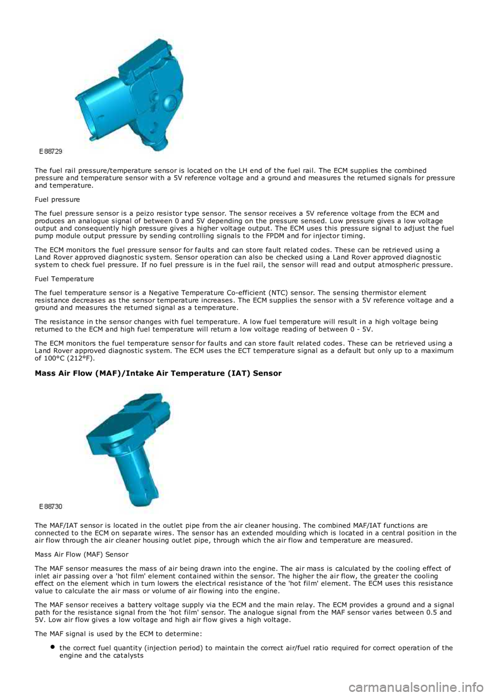
The fuel rai l pres sure/t emperature s ens or is locat ed on t he LH end of t he fuel rai l. The ECM suppli es the combinedpres s ure and t emperat ure s ensor wi th a 5V reference volt age and a ground and meas ures t he ret urned s ignals for pres s ureand t emperature.
Fuel pres s ure
The fuel pres s ure s ens or i s a peizo res is tor t ype sens or. The s ensor receives a 5V reference vol tage from the ECM andproduces an anal ogue s i gnal of between 0 and 5V depending on the pres s ure sens ed. Low pres sure gives a l ow volt ageoutput and cons equent ly hi gh pres s ure gives a hi gher volt age output. The ECM uses t his press ure s ignal t o adjus t t he fuelpump module out put pres sure by s endi ng cont rol ling si gnal s t o the FPDM and for i nject or ti ming.
The ECM moni tors the fuel pres sure s ens or for faul ts and can st ore fault related codes. Thes e can be ret ri eved us i ng aLand Rover approved diagnos t ic s ys tem. Sensor operat ion can als o be checked us i ng a Land Rover approved diagnos t ics ys t em t o check fuel pres sure. If no fuel pres s ure is i n t he fuel rai l, t he s ens or wil l read and output at mospheri c pres s ure.
Fuel Temperat ure
The fuel t emperature s ens or is a Negat ive Temperat ure Co-efficient (NTC) sens or. The s ens i ng thermis t or el ementres is t ance decreas es as the sens or temperat ure increases . The ECM s upplies t he s ensor wi th a 5V reference volt age and aground and meas ures t he ret urned s ignal as a t emperature.
The res is t ance i n t he s ens or changes wi th fuel temperat ure. A l ow fuel t emperat ure wi ll res ult i n a hi gh volt age bei ngret urned t o t he ECM and high fuel temperat ure wil l return a l ow volt age reading of between 0 - 5V.
The ECM moni tors the fuel temperat ure sens or for fault s and can s tore faul t rel at ed codes . These can be ret rieved us ing aLand Rover approved diagnos t ic s ys tem. The ECM us es t he ECT t emperature s ignal as a default but only up to a maximumof 100°C (212°F).
Mass Air Flow (MAF)/Intake Air Temperature (IAT) Sensor
The MAF/IAT s ensor i s located i n t he out let pi pe from t he air cleaner hous ing. The combined MAF/IAT funct ions areconnected t o t he ECM on separat e wi res . The sens or has an ext ended moul ding whi ch is l ocat ed in a cent ral posi ti on in theair flow through t he air cleaner hous ing out let pipe, t hrough which t he air flow and t emperat ure are meas ured.
Mas s Air Flow (MAF) Sensor
The MAF s ensor meas ures t he mas s of air being drawn int o t he engi ne. The ai r mas s is calculat ed by t he cool ing effect ofinl et ai r pas s ing over a 'hot fil m' element cont ained wi thin the s ens or. The higher the ai r fl ow, the great er the cooli ngeffect on the el ement whi ch in t urn lowers the el ect ri cal res i st ance of t he 'hot film' el ement. The ECM us es t his resi s tancevalue t o calcul ate the ai r mass or vol ume of air flowing i nto the engine.
The MAF s ensor receives a bat tery volt age supply vi a t he ECM and t he main relay. The ECM provi des a ground and a s i gnalpath for the res is tance s ignal from t he 'hot film' sens or. The analogue s ignal from t he MAF s ens or varies bet ween 0.5 and5V. Low air flow gi ves a low vol tage and hi gh air fl ow gi ves a high volt age.
The MAF s ignal is us ed by t he ECM t o det ermi ne:
t he correct fuel quant it y (injecti on peri od) t o mai ntain the correct ai r/fuel rat io required for correct operat ion of t heengi ne and t he cat alys ts
Page 1208 of 3229
int o t he int ake manifol d.
Throt tl e Posi ti on (TP) Sensor
The TP s ensor i s hous ed i n t he elect ric t hrott le ass embly and is us ed t o check t he posi ti on of the throt t le di sc. Twopermanent magnet s i n t he sens or connect ed t o t he thrott le di sc affect t wo Hall effect sens ors . As t he s pi ndl e i s rot atedt he magnet s rot ate around t he Hall effect s ensors and produce offset analogue s ignals back t o t he ECM. The ECMcompares t hes e s ignals to st ored values t o ens ure t hat they s how an accurate throt tle dis c pos it ion. The offset s i gnals aret hat one Hal l effect s ens or produces a higher vol tage as t he t hrott le angl e increas es and the ot her sens or produces alower volt age as the throt tl e angle i ncreases .
The ECM performs a s elf t est and a cal ibrat ion routi ne on the throt t le di sc pos it ion at each igni ti on cycle. This i s achi evedby t he ECM poweri ng the damper mot or to full y clos e t he throt t le di sc and then ful ly open t he t hrott le dis c.
The ECM moni tors the DC damper motor and t he TP s ens or for faul ts and can st ore fault related codes. Thes e can beret ri eved us i ng a Land Rover approved diagnos t ic s ys tem.
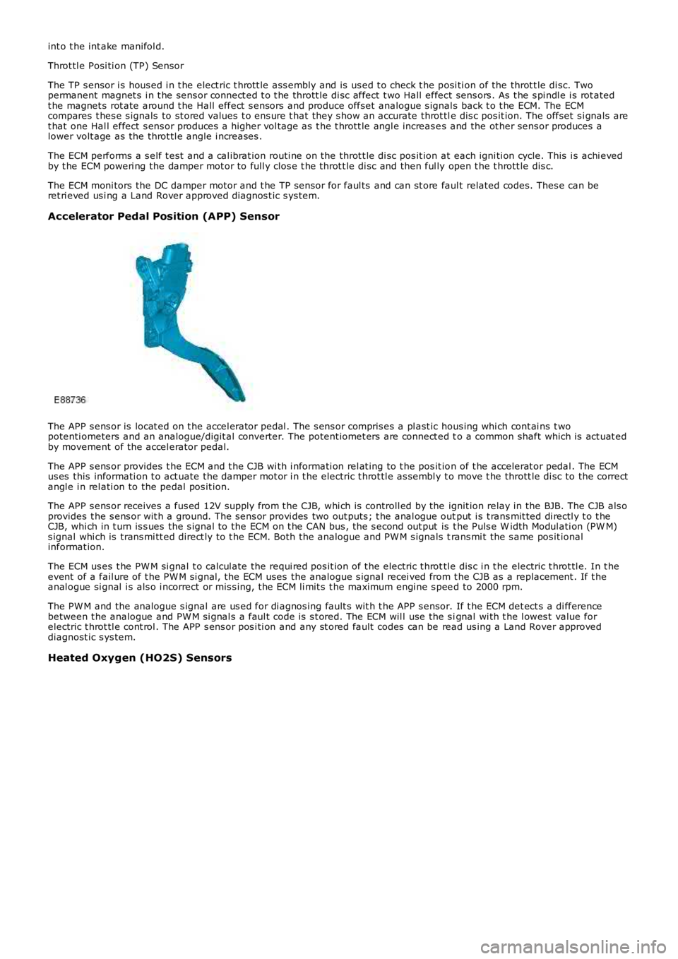
Accelerator Pedal Position (APP) Sensor
The APP s ens or is locat ed on t he accel erator pedal . The s ens or compris es a pl ast ic hous ing whi ch cont ai ns t wopotenti ometers and an analogue/digit al convert er. The potent iomet ers are connect ed to a common shaft which is act uat edby movement of the accel erator pedal.
The APP s ens or provides t he ECM and t he CJB wi th i nformati on rel at ing to t he pos it ion of t he accelerat or pedal . The ECMus es this informati on t o act uate the damper mot or i n t he electric t hrot tl e as sembl y t o move t he thrott le di sc to the correctangl e i n rel ati on to the pedal pos it ion.
The APP s ens or receives a fus ed 12V s upply from t he CJB, whi ch is controll ed by the ignit ion relay in the BJB. The CJB als oprovides t he s ens or wit h a ground. The s ens or provi des two out puts ; t he anal ogue output i s t rans mit ted di rectl y t o t heCJB, whi ch in t urn is s ues the s ignal to the ECM on t he CAN bus , the s econd out put is t he Puls e W idth Modul ati on (PW M)s ignal whi ch is trans mi tt ed direct ly to t he ECM. Both the analogue and PW M s ignals trans mi t the s ame pos it ionalinformat ion.
The ECM us es t he PW M si gnal t o calcul ate the requi red pos it ion of t he electric t hrottl e dis c i n t he electric t hrot tl e. In t heevent of a fail ure of t he PW M si gnal , the ECM uses the analogue s ignal recei ved from t he CJB as a replacement . If t heanal ogue si gnal i s als o i ncorrect or mis s ing, the ECM li mit s t he maximum engi ne s peed to 2000 rpm.
The PW M and the analogue s ignal are us ed for di agnos ing fault s wit h t he APP s ensor. If t he ECM det ect s a di fferencebetween t he analogue and PW M si gnal s a faul t code is s t ored. The ECM wil l use the s ignal wi th t he l owes t value forelectric t hrot tl e cont rol . The APP s ens or pos i ti on and any st ored fault codes can be read us ing a Land Rover approveddiagnost ic s ys tem.
Heated Oxygen (HO2S) Sensors
Page 1209 of 3229
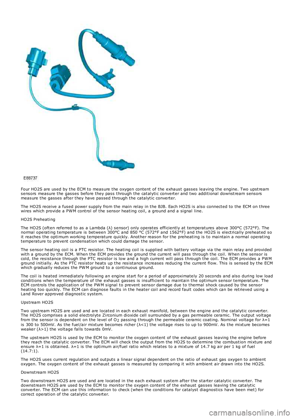
Four HO2S are us ed by t he ECM t o meas ure t he oxygen content of t he exhaus t gas s es leaving t he engine. Two upst reams ens ors measure t he gas s es before they pas s t hrough the cat al yti c convert er and two addi ti onal downst ream s ens orsmeas ure t he gass es after t hey have pas sed through t he catalyt ic converter.
The HO2S receive a fus ed power supply from t he main rel ay in t he BJB. Each HO2S i s als o connect ed to the ECM on t hreewires which provi de a PW M cont rol of t he s ens or heat ing coil , a ground and a si gnal l ine.
HO2S Preheati ng
The HO2S (oft en referred to as a Lambda (λ) s ensor) only operat es efficientl y at temperatures above 300°C (572°F). Thenormal operat ing t emperature is bet ween 300°C and 850 °C (572°F and 1562°F) and the HO2S is el ect ri cal ly preheat ed s oit reaches t he opti mum working t emperature quickly. Anot her reas on for t he preheat ing is t o mai ntain a normal operat ingt emperature to prevent condens ati on which could damage t he s ensor.
The s ens or heat ing coi l i s a PTC res is tor. The heat ing coil i s s uppl ied wi th bat tery volt age vi a t he main relay and provi dedwit h a ground by t he ECM. W hen t he ECM provides t he ground t he current wi ll pass through t he coil . W hen t he sens or iscol d, the res is tance t hrough the PTC res is tor i s low and a high current wil l pas s t hrough t he coi l. The ECM provi des a PW Mground i ni ti ally. As t he PTC resi st or heat s up t he res i st ance increases reduci ng the current fl ow. Thi s is sens ed by t he ECMwhich graduall y reduces the PW M ground to a cont inuous ground.
The coi l is heat ed immedi ately foll owing an engine st art for a peri od of approxi mately 20 s econds and als o duri ng low loadcondi ti ons when the t emperat ure of t he exhaus t gas s es is ins uffi cient to maint ai n t he opti mum s ens or t emperat ure. TheECM controls t he appl icati on of the PW M s i gnal t o prevent sens or damage due t o t hermal s hock caus ed by the sens orheat ing too quickly. The ECM can diagnos e fault s i n t he heat er coi l and record faul t codes whi ch can be ret rieved us ing aLand Rover approved diagnos t ic s ys tem.
Ups tream HO2S
Two ups tream HO2S are us ed and are l ocat ed in each exhaus t mani fold, between the engine and t he catalyt ic converter.The HO2S compri ses a s ol id el ect rol yt e Zi rconium di oxi de cel l s urrounded by a gas permeabl e ceramic. The output volt agefrom the s ensor i s dependent on the level of O2 pas s ing t hrough t he permeable ceramic coat ing. Nomi nal volt age for λ=1is 300 to 500mV. As t he fuel /ai r mixt ure becomes ri cher (λ<1) t he volt age ri ses t o up t o 900mV. As t he mi xt ure becomesweaker (λ>1) the volt age fal ls t owards 0mV.
The upst ream HO2S i s used by the ECM to monit or t he oxygen content of t he exhaus t gas s es leaving t he engine beforet hey reach the catal yt ic convert er. The ECM wi ll check t he output from the HO 2S to det ermi ne t he combus t ion mi xture andensure λ=1 i s obtained. λ=1 is the opt imum air/fuel rati o which relat es to a mi xt ure of 14.7 kg air per 1 kg of fuel(14.7:1).
The HO2S us es current regul at ion and out put s a linear s ignal dependent on t he rati o of exhaus t gas oxygen to ambientoxygen. The oxygen cont ent of the exhaus t gas ses is meas ured by compari ng it wit h ambient air drawn int o t he HO2S.
Downst ream HO2S
Two downs tream HO2S are us ed and are l ocat ed in the each exhaus t s ys t em after t he s tarter cat alyt ic converter. Thedownst ream HO2S are used by the ECM to moni tor t he oxygen content of the exhaust gass es leaving t he cat alyt icconvert er. The ECM can us e t his i nformati on to check (when the condit ions for catal ys t diagnost ics have been met ) forcorrect operati on of the cat alyti c convert er.
Page 1211 of 3229
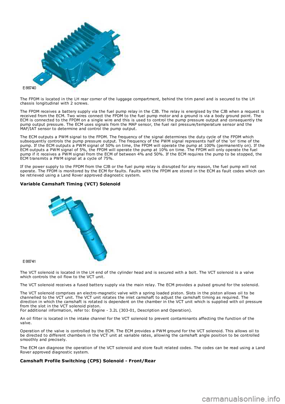
The FPDM i s located i n t he LH rear corner of the l uggage compart ment, behind t he t rim panel and is s ecured t o t he LHchas s is l ongi tudinal wi th 2 s crews.
The FPDM receives a bat tery s uppl y via t he fuel pump relay i n t he CJB. The relay is energis ed by t he CJB when a reques t isreceived from the ECM. Two wires connect t he FPDM t o t he fuel pump mot or and a ground i s via a body ground poi nt. TheECM i s connected t o t he FPDM on a si ngle wi re and this is us ed t o cont rol t he pump pres s ure out put and cons equentl y t hepump output pres s ure. The ECM us es s ignals from t he MAP s ens or, the fuel rail pres s ure/t emperat ure s ens or and t heMAF/IAT s ensor t o determine and control the pump out put.
The ECM out put s a PW M s ignal to the FPDM. The frequency of t he s ignal det ermi nes the dut y cycle of t he FPDM whi chs ubs equent ly controls t he pump press ure out put. The frequency of t he PW M s ignal repres ent s half of t he 'on' ti me of t hepump. If t he ECM out put s a PW M s ignal of 50% on t ime, the FPDM will operat e t he pump at 100% (permanentl y on). If theECM out put s a PW M s ignal of 5%, the FPDM wil l operat e t he pump at 10% on t ime. The FPDM wi ll only operat e t he fuelpump i f it receives a PW M s i gnal from the ECM of bet ween 4% and 50%. If t he ECM requi res t he pump t o be s t opped, theECM t rans mit s a PW M s i gnal at a cycl e of 75%.
If the power s uppl y to the FPDM from t he CJB or the fuel pump rel ay is di srupt ed for any reason, t he fuel pump wi ll notoperate. The FPDM i s monit ored by the ECM for faul ts . Faul ts wit h t he FPDM are st ored i n t he ECM as faul t codes whi ch canbe ret rieved usi ng a Land Rover approved diagnost ic sys tem.
Variable Camshaft Timing (VCT) Solenoid
The VCT s olenoid i s located in t he LH end of t he cyl inder head and i s s ecured wit h a bol t. The VCT s olenoid is a val vewhich controls t he oil flow t o t he VCT unit .
The VCT s olenoid recei ves a fus ed batt ery s upply vi a the main relay. The ECM provides a pul s ed ground for t he s olenoi d.
The VCT s olenoid compri s es an electro-magneti c val ve wit h a spring l oaded pi st on. Slots in t he pis t on all ows oil to bechannell ed to the VCT uni t. The VCT uni t rot at es t he inlet cams haft t o adjus t the cams haft t iming as requi red. Thedirect ion i n which t he cams haft is rot at ed i s dependent on the chamber in t he VCT unit whi ch is suppli ed wit h oil press urefrom the s lot i n t he VCT s olenoid pi st on.For addit ional informat ion, refer t o: Engi ne - 3.2L (303-01, Descripti on and Operat ion).
An oil fil ter i s located i n t he int ake channel for the VCT sol enoid to prevent contami nant s affect ing the funct ion of t hevalve.
Operat ion of t he val ve is controll ed by the ECM. The ECM provides a PW M ground for the VCT sol enoi d. This allows oi l tobe direct ed t o different chambers i n t he VCT unit at vari abl e rat es , al lowi ng the cams haft angle pos it ion t o be controll eds moothly and precis ely.
The ECM can diagnose the operat ion of t he VCT s olenoid and st ore fault related codes. The codes can be read us ing a LandRover approved diagnost ic sys tem.
Camshaft Profile Switching (CPS) Solenoid - Front/Rear