2006 LAND ROVER FRELANDER 2 relay
[x] Cancel search: relayPage 1772 of 3229
il lumi nat ed for t he remaining 2 s econds of the bulb check, this indicates t hat faults are st ored in t he ABS module memory.
If the warning i ndi cat or was il luminat ed due to a wheel speed s ensor faul t, t he i ndicat or will remain ill uminat ed at thenext i gnit ion cycl e, even i f the fault is recti fi ed. W hen the vehicle is driven above a s peed of 20 km/h (12.5 mph) theindicat or wi ll be ext ingui s hed. This al lows t he ABS module to perform a thorough check of t he s yst em and to es t abl is h t hatt he out put from t he repl aced s ensor i s correct .
Low Fuel Level Indicator
The low fuel level indicator is cont roll ed by t he fuel level gage s oftware (s ee above). W hen t he vehicle ent ers power mode6, the low fuel i ndicat or is ill uminat ed in an amber color for a 3 s econd bulb check. If t he fuel level gage softwaredetermines t he low fuel indicator s houl d be i ll uminated, it flas hes t he indicator at a rate of 2 Hz for 5 seconds . The firstfl ash is accompani ed by a chime from t he ins t rument clus ter s ounder. After t he 5 s econd fl as hing period t he indi cat or willremai n i llumi nated unt il fuel is added t o t he t ank or t he vehi cle i gni ti on is swi tched off.
Parking Brake Indicator
The red parking brake i ndi cat or is i ll uminated on receipt of a medium s peed CAN bus s ignal from t he CJB. The s ignalori ginates i n t he parking brake micros wit ch, whi ch is hardwired to the CJB. The parking brake indicator wil l onl y i llumi nateif t he parking brake is appli ed and t he vehi cl e is in power mode 6.
Rear Fog Lamp Indicator
The rear fog lamp indicator is il luminat ed on receipt of a medi um s peed CAN bus s ignal from t he CJB. The i ndicat or isil lumi nat ed i n an amber col or if t he vehi cl e is in power mode 6 and rear fog l amp operat ion has been reques ted.
Front Fog Lamp Indicator
The front fog l amp i ndi cat or is i ll uminated on recei pt of a medium s peed CAN bus si gnal from the CJB. The indi cat or i sil lumi nat ed i n a green color i f the vehicle is i n power mode 6 and front fog lamp operat ion has been reques ted.
Adaptive Front Lighting System Indicator
The Adapt ive Front l ight ing Syst em (AFS) indicator i s cont rol led by t he AFS module. The AFS module i s hardwi red t o t heCJB, whi ch relays s ignals to the i nst rument clus ter over the medi um s peed CAN bus . When t he vehi cl e enters power mode6, the AFS indicator is ill uminat ed in an amber color for a 3 s econd bul b check. If duri ng AFS operati on a faul t is det ect ed,t he AFS indicator wi ll fl ash at a frequency of 2 Hz.
Speed Control Indicator
The s peed control indicator i s cont roll ed by t he ECM, which t rans mit s a s peed cont rol acti ve si gnal t o t he ins t rumentclus ter via the CJB. The indicator wi ll il lumi nat e i n an amber col or when the vehicle is i n power mode 6 and s peed cont rolis act ive.
Trailer Indicator
The t rail er indicator is cont roll ed by t he ins trument cl ust er on receipt of medium speed CAN bus si gnal s from the CJB.W hen a trailer i s connected t o t he vehi cle el ect ri cal s ys t em and t he t urn s i gnal indicat or s wi tch i s operated, t he CJBt ransmit s a s ignal to the ins trument cl us t er to operat e t he t rail er indicator. The inst rument clus t er s oftware cont rol s thefl ash rat e of the indicator which flas hes in a green color. The t rai ler indi cat or flas hes s lowly, at t he s ame rat e as t he t urns ignal indicators .
Low Washer Fluid Indicator
The low washer fluid indicator is il luminat ed on receipt of a medi um s peed CAN bus signal from t he CJB. The s i gnalori ginates i n t he low washer fl uid l evel s wit ch, whi ch is hardwired to the CJB.
The amber low was her fl uid i ndi cat or is s ubject t o a 3 second bul b check when the vehicle ent ers power mode 6. If a lowwas her fluid level is detect ed for more t han 15 seconds when the vehicle is i n power mode 6, the ins trument cl us t er wil lil lumi nat e t he indi cat or.
Low Engine Coolant Level Warning Ind icator
The low engi ne cool ant l evel warni ng indicat or i s il lumi nat ed on recei pt of a medium speed CAN bus s i gnal from the CJBwhen t he vehi cl e is in power mode 6. The s ignal origi nat es in the ECM, whi ch trans mits the s i gnal t o t he CJB over t he highs peed CAN bus.
W hen t he vehicle ent ers power mode 6, the amber l ow engine coolant level warning i ndi cat or is i ll uminated for a 3 secondbulb check. If the warning i ndi cat or remai ns ill uminat ed aft er this period, the engine cooli ng s yst em s hould be checked forleaks and t opped up as necess ary.
Transmission Warning Indicator
The t ransmis s ion warni ng indi cat or di spl ays aut omati c transmis s ion and acti ve-on demand coupli ng warni ngs . The warni ngindicat or i s il lumi nat ed on recei pt of medi um s peed CAN bus s ignals from t he CJB. The s ignals origi nat e i n theTrans mis s ion Cont rol Modul e (TCM) and the act ive-on demand coupl ing control modul e res pect ively and are t rans mi tt ed tot he CJB over t he high s peed CAN bus .
The t ransmis s ion warni ng indi cat or i s a dual col or indicator, whi ch is subject t o a 3 second bulb check when the vehicleenters power mode 6. For t he fi rs t 1.5 seconds of the bulb check t he indicator i llumi nates i n an amber col or, fol lowed by1.5 seconds ill uminat ed in a red color.
The t abl e below det ails warning i ndicat or col or agai ns t mes s age cent er mess age.
Page 1783 of 3229
Publi s hed: 11-May-2011
Horn - Horn
Des cript ion and Operat ion
COMPONENT LOCATION
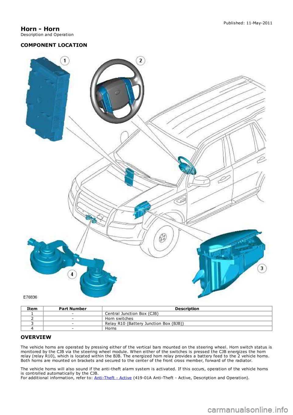
ItemPart NumberDescription1-Central Juncti on Box (CJB)
2-Horn s wit ches
3-Relay R10 (Bat tery Juncti on Box (BJB))4-Horns
OVERVIEW
The vehi cl e horns are operat ed by pres si ng eit her of t he vert ical bars mounted on the s t eering wheel . Horn s wit ch s tat us ismonit ored by t he CJB via the s t eering wheel module. W hen ei ther of the s wi tches is press ed t he CJB energizes t he hornrel ay (relay R10), whi ch is l ocat ed wit hin the BJB. The energized horn relay provi des a bat t ery feed to the 2 vehi cl e horns .Both horns are mount ed on brackets and s ecured t o t he cent er of t he front cros s member, forward of the radiat or.
The vehi cl e horns will al so sound i f the ant i-theft al arm s ys t em i s act ivat ed. If thi s occurs , operat ion of t he vehi cl e hornsis cont roll ed automat ically by the CJB.For addit ional informat ion, refer t o: Anti -Theft - Act ive (419-01A Anti -Theft - Acti ve, Des cri pt ion and Operati on).
Page 1784 of 3229
Publi s hed: 11-May-2011
Horn - Horn
Diagnosi s and Tes ti ng
Principles of Operation
For a detail ed descripti on of the horn s yst em, refer to the relevant Des cri pt ion and Operati on s ect ion i n t he works hopmanual.REFER to: Horn (413-06 Horn, Descripti on and Operat ion).
Inspection and Verification
CAUTION: Di agnos is by s ubs ti tut ion from a donor vehicle is NO T acceptabl e. Subs ti tut ion of cont rol modules doesnot guarant ee confirmat ion of a faul t, and may als o caus e addit ional fault s i n t he vehi cl e being t est ed and/or t he donorvehi cl e.
1. Verify t he cus t omer concern.1.
2. Vis ually ins pect for obvious s igns of mechani cal or electrical damage.2.
Visual InspectionMechanicalElectrical
Horn s wit chesClock s pri ng/s teeri ng angle s ensorHorns
Fus es/rel ays (refer to elect rical guide)W iring harnes sCorrect engagement of el ect ri cal connect orsLoos e or corroded connecti onsCent ral Juncti on Box (CJB)Bat tery Juncti on Box (BJB)
3. If an obvious cause for an obs erved or report ed concern is found, correct t he caus e (if pos s ible) beforeproceeding t o t he next s t ep.3.
4. If t he caus e is not vis ually evi dent , check CJB for Di agnos ti c Trouble Codes (DTCs ) and refer t o the DTC Index.4.
DTC Index
• NOTE: If the control modul e or a component i s s us pect and the vehicle remains under manufacturer warrant y, refer t o theW arranty Pol icy and Procedures manual (s ect ion B1.2), or determine i f any pri or approval programme is in operat ion, pri ort o the ins tall ati on of a new module/component.
• NOTE: Generic scan t ool s may not read the codes li st ed, or may read only fi ve digit codes . Mat ch the five di git s from t hes can tool to the firs t fi ve di git s of the seven digi t code l is ted to ident ify t he faul t (t he las t t wo digi ts gi ve ext rainformat ion read by the manufact urer-approved diagnost ic s ys tem).
• NOTE: W hen performing volt age or res is t ance t est s , always use a digi tal mult imeter (DMM) accurat e t o t hree deci malplaces and wit h a current cal ibrat ion cert ificate. W hen tes ti ng res i st ance, always take the res is tance of the DMM l eads i ntoaccount.
• NOTE: Check and recti fy bas ic faul ts before beginni ng diagnos t ic rout ines i nvol vi ng pinpoint t es t s.
• NOTE: If DTCs are recorded and, aft er performi ng the pi npoi nt tes ts , a fault is not present , an int ermi tt ent concern maybe t he caus e. Always check for loose connect ions and corroded terminals .
DT CDescriptionPossible CauseActionB1C5512Horn Relay Coil Ci rcuit -circui t s hort to powerHorn relay control ci rcuit -s hort to powerRefer t o el ect ri cal circui t di agrams and checkhorn rel ay cont rol circuit for s hort to power
B1C5514Horn Relay Coil Ci rcuit - ci rcuits hort t o ground or openHorn relay control ci rcuit -s hort to ground, open circui tRefer t o el ect ri cal circui t di agrams and checkhorn rel ay cont rol circuit for s hort to ground,open circui t
U012600Los t Communicati on W i thSt eering Angle Sens or Modul eLos t communicati on wit hs teeri ng angl e s ensorCarry out t he ass ociat ed net work tes t for t hisDTC us i ng the manufact urer approveddi agnos ti c s ys t em
Page 1805 of 3229
Publi s hed: 11-May-2011
Parking Aid - Parking Aid
Diagnosi s and Tes ti ng
Principle of Operation
For a detail ed descripti on of the parki ng aid sys tem, refer t o t he rel evant Des cription and Operat ion s ecti on in theworks hop manual .REFER to: Parki ng Aid (413-13 Parki ng Aid, Descripti on and Operat ion).
Inspection and Verification
CAUTION: Di agnos is by s ubs ti tut ion from a donor vehicle is NO T acceptabl e. Subs ti tut ion of cont rol modules doesnot guarant ee confirmat ion of a faul t, and may als o caus e addit ional fault s i n t he vehi cl e being t est ed and/or t he donorvehi cl e.
1. Verify t he cus t omer concern.1.
2. Vis ually ins pect for obvious s igns of damage and s ys t em i ntegri ty.2.
• NOTE: Part icular att enti on s hould be paid t o t he fol lowi ng it ems where DTCs may not be logged:
Check for cont aminati on (e.g. dirt, gri me, fros ti ng, i ce) around t he parking ai d s ensors, i f s o refer to the parki ng aids ect ion i n t he vehi cl e handbook.Check for the correct ins tall ati on and ali gnment of t he s ens ors to t he bumper.Spurious det ect ion of t he ground may occur duri ng front s ys t em operat ion on an up-s lope, or down s l ope.
Visual Inspection
ElectricalFuse(s )Relay(s )W iri ng Harnes sElectrical connect or(s )Front parking ai d s ensor(s ) and holdersRear parking aid s ens or(s ) and hol dersAudio s ys tem.REFER to: Informati on and Entert ainment Syst em (415-01 Informati on and Entertainment Sys tem, Di agnos is andTes ti ng).Parking ai d s wit ch and LEDParking ai d module
3. If an obvious cause for an obs erved or report ed concern is found, correct t he caus e (if pos s ible) beforeproceeding t o t he next s t ep.3.
4. If t he caus e is not vis ually evi dent , check for Di agnos ti c Trouble Codes (DTCs) and refer t o t he DTC Index.4.
DTC Index
• NOTE: If the control modul e is sus pect and t he vehicle remains under manufact urer warranty, refer to the W arrant y Poli cyand Procedures manual (s ect ion B1.2), or determine i f any prior approval programme is i n operat ion, prior t o t heins t al lat ion of a new modul e.
• NOTE: Generic scan t ool s may not read the codes li st ed, or may read only fi ve digit codes . Mat ch the five di git s from t hes can tool to the firs t fi ve di git s of the seven digi t code l is ted to ident ify t he faul t (t he las t t wo digi ts gi ve addi ti onalinformat ion read by the manufact urer approved diagnos t ic s ys tem).
• NOTE: W hen performing volt age or res is t ance t est s , always use a digi tal mult imeter (DMM) accurat e t o t hree deci malplaces, and wi th an up-t o-date cal ibrat ion cert ificate. W hen tes ti ng res is t ance al ways take t he res is t ance of t he DMMleads i nt o account .
• NOTE: Check and recti fy bas ic faul ts before beginni ng diagnos t ic rout ines i nvol vi ng pinpoint t es t s.
• NOTE: Ins pect connect ors for s igns of water ingres s , and pins for damage and/or corros ion.
• NOTE: If DTCs are recorded and, aft er performi ng the pi npoi nt tes ts , a fault is not present , an int ermi tt ent concern maybe t he caus e. Always check for loose connect ions and corroded terminals .
• NOTE: W hen carrying out repair/di agnos is of t he s yst em, on removal of t he front or rear bumper ins pect t he s ensorconnectors to ens ure they were correct ly l atched and check fly l eads for si gns of chaffing or t rapped wi res .
For a compl ete lis t of all Di agnos ti c Trouble Codes (DTCs) t hat could be logged on this vehicle, pleas e refer to Sect ion100-00
REFER to: Di agnos ti c Trouble Code (DTC) Index - DTC: Parking Ai d Module (PAM) (100-00 General Informat ion, Des cri pti onand Operat ion).
Page 1813 of 3229
Publi shed: 14-Jul-2011
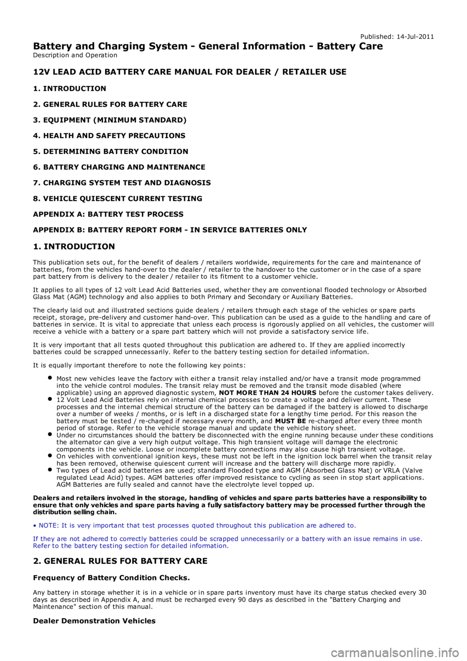
Battery and Charging System - General Information - Battery Care
Des cript ion and Operat ion
12V LEAD ACID BATTERY CARE MANUAL FOR DEALER / RETAILER USE
1. INTRODUCTION
2. GENERAL RULES FOR BATTERY CARE
3. EQU IPMENT (MINIMU M STANDARD)
4. HEALTH AND SAFETY PRECAUTIONS
5. DETERMINING BATTERY CONDITION
6. BATTERY CHARGING AND MAINTENANCE
7. CHARGING SYSTEM TEST AND DIAGNOSIS
8. VEHICLE QUIESCENT CURRENT TESTING
APPENDIX A: BATTERY TEST PROCESS
APPENDIX B: BATTERY REPORT FORM - IN SERVICE BATTERIES ONLY
1. INTRODUCTION
This publi cat ion s ets out , for t he benefit of dealers / ret ailers worl dwide, requirement s for the care and maint enance ofbatt eri es , from the vehicles hand-over to the dealer / retail er to the handover t o the cus t omer or i n t he cas e of a sparepart batt ery from i s delivery to the dealer / retail er to it s fi tment t o a cus tomer vehicle.
It appl ies t o all t ypes of 12 volt Lead Acid Bat teries us ed, whet her they are convent ional fl ooded t echnology or Abs orbedGlas s Mat (AGM) technol ogy and als o applies to bot h Pri mary and Secondary or Auxi li ary Bat teri es.
The clearl y lai d out and ill ust rat ed s ect ions guide dealers / ret ail ers t hrough each st age of the vehicl es or s pare partsreceipt , st orage, pre-del ivery and cus tomer hand-over. This publi cat ion can be us ed as a gui de to the handli ng and care ofbatt eri es in s ervi ce. It is vi tal t o appreci ate that unles s each proces s i s ri gorousl y appl ied on al l vehi cl es, t he cust omer wil lreceive a vehicl e wit h a bat tery or a s pare part bat t ery which will not provide a s at is fact ory s ervi ce life.
It is very import ant that all t est s quoted throughout this publ icat ion are adhered to. If t hey are appli ed incorrect lybatt eri es could be s crapped unneces s ari ly. Refer to the bat tery tes t ing s ect ion for detail ed informat ion.
It is equally important therefore to not e t he fol lowing key point s :
Mos t new vehi cl es leave t he factory wi th ei ther a t rans it relay i ns t alled and/or have a trans it mode programmedint o t he vehi cl e cont rol modules . The t rans it rel ay mus t be removed and t he t rans it mode di sabled (whereappl icable) us ing an approved diagnost ic sys tem, NOT MO RE T HAN 24 HOURS before t he cust omer t akes deli very.12 Volt Lead Acid Bat teries rely on i nternal chemical proces s es to create a vol tage and deli ver current. Theseprocess es and t he int ernal chemi cal s truct ure of the bat tery can be damaged i f the bat tery is allowed t o di schargeover a number of weeks / months , or is left i n a di scharged s t at e for a lengt hy ti me peri od. For t hi s reas on t hebatt ery mus t be t es ted / re-charged i f neces sary every mont h, and MUST BE re-charged after every t hree mont hperi od of st orage. Refer to the vehicle st orage manual and updat e t he vehi cl e his t ory s heet.Under no ci rcums tances should the bat tery be dis connected wit h the engi ne running becaus e under thes e condi ti onst he alt ernator can give a very high output volt age. This hi gh t rans ient vol tage wi ll damage t he electroni ccomponents in t he vehicle. Loos e or i ncompl et e bat tery connect ions may al s o caus e high transi ent volt age.On vehicles wi th conventi onal ignit ion keys , thes e mus t not be left in t he i gni ti on lock barrel when the t rans it relayhas been removed, ot herwi se qui escent current wi ll increas e and t he bat t ery wi ll discharge more rapi dl y.Two t ypes of Lead acid bat teri es are us ed; s tandard Fl ooded t ype and AGM (Absorbed Glas s Mat) or VRLA (Valveregulat ed Lead Aci d) types. AGM batt eries offer i mproved res is t ance t o cycl ing as seen i n s top st art appli cat ions .AGM Bat teries are ful ly s ealed and cannot have t he electrolyte level t opped up.
Dealers and retailers involved in the storage, handling of vehicles and spare parts batteries have a responsibility toensure that only vehicles and spare parts having a fully satisfactory battery may be processed further through thedistribution selling chain.
• NOTE: It is very important that t est proces s es quot ed t hroughout t hi s publicati on are adhered to.
If they are not adhered t o correct ly bat teries could be scrapped unneces saril y or a batt ery wit h an is s ue remains in use.Refer t o t he bat t ery t est ing s ecti on for detai led i nformat ion.
2. GENERAL RULES FOR BATTERY CARE
Frequency of Battery Cond ition Checks.
Any batt ery i n s torage whether it i s in a vehi cle or i n s pare part s i nventory mus t have it s charge s tat us checked every 30days as des cri bed in Appendix A, and mus t be recharged every 90 days as des cribed i n t he "Bat tery Charging andMaint enance" secti on of thi s manual.
Dealer Demonstration Vehicles
Page 1821 of 3229
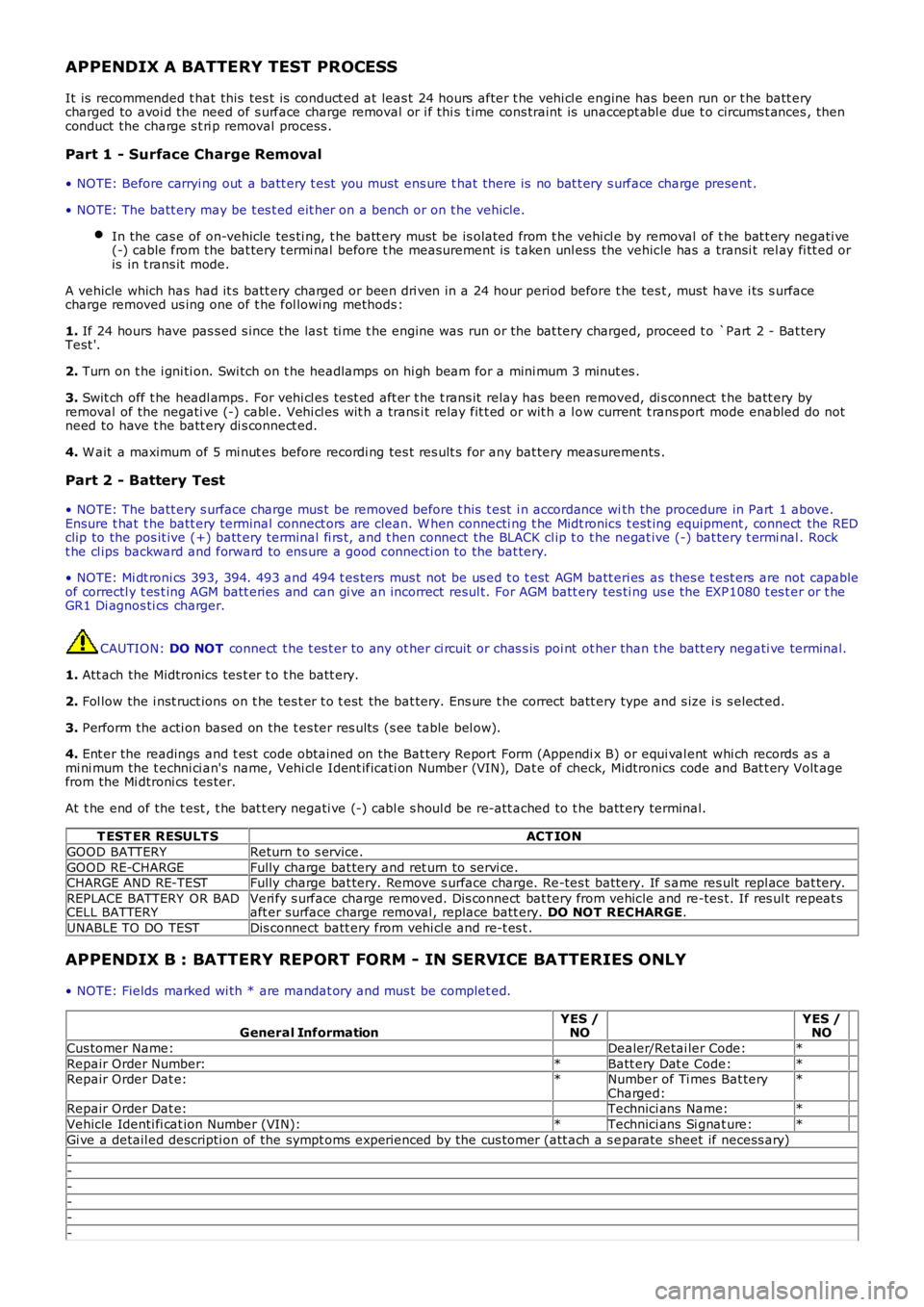
APPENDIX A BATTERY TEST PROCESS
It is recommended t hat this tes t is conduct ed at leas t 24 hours after t he vehi cl e engine has been run or t he batt erycharged to avoi d the need of s urface charge removal or i f thi s t ime cons traint is unaccept abl e due t o circums t ances , thenconduct the charge s t ri p removal process .
Part 1 - Surface Charge Removal
• NOTE: Before carryi ng out a batt ery t est you must ens ure t hat there is no bat t ery s urface charge present .
• NOTE: The batt ery may be t es t ed eit her on a bench or on t he vehicle.
In the cas e of on-vehicle tes ti ng, t he batt ery must be is olated from t he vehi cl e by removal of t he bat t ery negati ve(-) cable from the bat tery t ermi nal before t he measurement is t aken unl ess the vehicle has a transi t rel ay fi tt ed oris in t rans it mode.
A vehicle which has had it s batt ery charged or been dri ven in a 24 hour period before t he tes t , must have i ts s urfacecharge removed us ing one of t he fol lowi ng methods :
1. If 24 hours have pas s ed s ince the las t ti me t he engine was run or the bat tery charged, proceed t o `Part 2 - Bat teryTest '.
2. Turn on t he i gni ti on. Swi tch on t he headlamps on hi gh beam for a mini mum 3 minut es .
3. Swit ch off t he headl amps . For vehi cl es tes t ed aft er t he t rans it relay has been removed, di s connect t he batt ery byremoval of the negati ve (-) cabl e. Vehi cl es wit h a trans i t relay fit t ed or wit h a l ow current t rans port mode enabled do notneed to have t he batt ery di s connect ed.
4. W ait a maximum of 5 mi nut es before recordi ng tes t res ult s for any bat tery measurements .
Part 2 - Battery Test
• NOTE: The batt ery s urface charge mus t be removed before t his t est i n accordance with the procedure in Part 1 above.Ensure t hat t he batt ery terminal connect ors are clean. W hen connecti ng t he Midt ronics t est ing equipment , connect the REDclip to the pos it ive (+) batt ery terminal fi rs t, and t hen connect the BLACK cl ip t o t he negat ive (-) bat tery t ermi nal . Rockt he cl ips backward and forward to ens ure a good connecti on to the bat tery.
• NOTE: Mi dt roni cs 393, 394. 493 and 494 t es ters mus t not be us ed t o t est AGM batt eri es as thes e t est ers are not capableof correctl y t es t ing AGM batt eries and can gi ve an incorrect resul t. For AGM batt ery tes ti ng us e the EXP1080 t es t er or t heGR1 Di agnos ti cs charger.
CAUTION: DO NOT connect t he t es t er to any ot her ci rcuit or chas s is poi nt ot her than t he batt ery negati ve terminal.
1. Att ach the Midtronics tes t er t o t he batt ery.
2. Fol low the i nst ruct ions on t he tes t er t o t est the bat tery. Ens ure t he correct batt ery type and s ize i s s elect ed.
3. Perform the acti on based on the t es ter res ult s (s ee table bel ow).
4. Ent er the readings and t es t code obtained on the Bat tery Report Form (Appendi x B) or equi val ent whi ch records as ami ni mum the t echni ci an's name, Vehi cl e Ident ificati on Number (VIN), Dat e of check, Midtronics code and Bat t ery Volt agefrom the Mi dtroni cs tes ter.
At t he end of the t est , t he bat t ery negati ve (-) cabl e s houl d be re-att ached to t he batt ery terminal.
T EST ER RESULT SACT ION
GOOD BATTERYReturn t o s ervice.
GOOD RE-CHARGEFully charge bat tery and ret urn to servi ce.CHARGE AND RE-TESTFully charge bat tery. Remove s urface charge. Re-tes t batt ery. If s ame res ult repl ace bat tery.
REPLACE BATTERY OR BADCELL BATTERYVeri fy s urface charge removed. Dis connect bat tery from vehicle and re-tes t. If res ult repeat saft er surface charge removal , replace batt ery. DO NOT RECHARGE.
UNABLE TO DO TESTDis connect batt ery from vehi cl e and re-t es t .
APPENDIX B : BATTERY REPORT FORM - IN SERVICE BATTERIES ONLY
• NOTE: Fields marked wi th * are mandat ory and mus t be complet ed.
General InformationYES /NO YES /NO
Cus tomer Name: Dealer/Retai ler Code:*
Repair Order Number:*Batt ery Dat e Code:* Repair Order Dat e:*Number of Ti mes Bat teryCharged:*
Repair Order Dat e: Technici ans Name:*
Vehicle Identi fi cat ion Number (VIN):*Technici ans Si gnat ure:*
Gi ve a detail ed descripti on of the sympt oms experienced by the cus tomer (att ach a s eparate sheet if necess ary)-
-
--
-
-
Page 1827 of 3229
Publi s hed: 11-May-2011
Battery, Mounting and Cables -
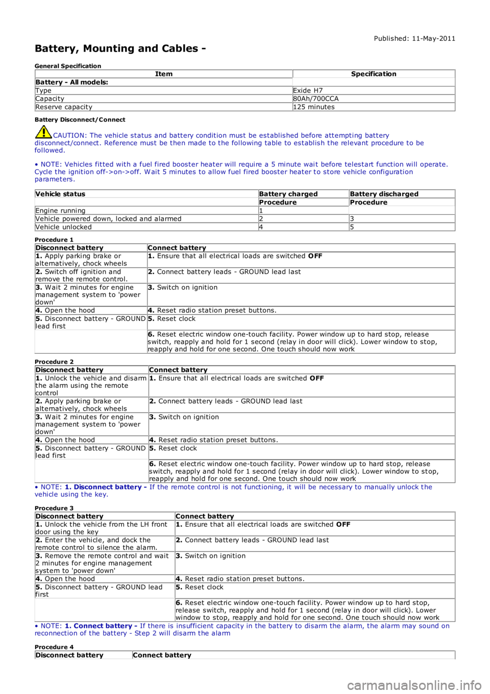
General SpecificationItemSpecification
Battery - All models:
TypeExide H7Capaci ty80Ah/700CCA
Res erve capacit y125 minutes
Battery Disconnect/C onnect
CAUTION: The vehicle s t atus and batt ery condit ion mus t be es t abl is hed before att empti ng bat t erydis connect/connect . Reference mus t be t hen made t o t he fol lowing table to es t abl is h t he rel evant procedure t o befol lowed.
• NOTE: Vehicles fit ted wit h a fuel fired boos t er heat er will requi re a 5 mi nute wait before tel es t art funct ion wi ll operate.Cycl e t he ignit ion off->on->off. W ai t 5 mi nutes t o all ow fuel fired boos t er heat er to s t ore vehicle confi gurati onparamet ers .
Vehicle statusBattery chargedBattery discharged
ProcedureProcedure
Engine runni ng1Vehicle powered down, l ocked and alarmed23
Vehicle unl ocked45
Procedure 1
Disconnect batteryConnect battery1. Apply parki ng brake oralt ernat ively, chock wheels1. Ens ure that all el ect ri cal loads are s wit ched O FF
2. Swit ch off i gni ti on andremove the remote cont rol.2. Connect bat t ery l eads - GROUND lead l ast
3. W ai t 2 mi nut es for enginemanagement sys tem t o 'powerdown'
3. Swit ch on ignit ion
4. Open t he hood4. Reset radi o s tat ion preset but tons .
5. Dis connect batt ery - GROUNDl ead firs t5. Reset clock
6. Reset elect ric window one-t ouch facili ty. Power window up t o hard s top, rel eas es wit ch, reapply and hol d for 1 s econd (relay i n door wil l cl ick). Lower window t o s top,reapply and hold for one s econd. One t ouch s hould now work
Procedure 2
Disconnect batteryConnect battery
1. Unlock t he vehi cl e and dis armt he alarm us ing t he remotecont rol
1. Ensure t hat al l el ect ri cal l oads are s wit ched OFF
2. Apply parki ng brake oralt ernat ively, chock wheels2. Connect batt ery l eads - GROUND l ead las t
3. W ai t 2 mi nut es for enginemanagement sys tem t o 'powerdown'
3. Swit ch on i gni ti on
4. Open t he hood4. Res et radio s t ati on pres et but tons .
5. Dis connect batt ery - GROUNDl ead firs t5. Res et cl ock
6. Res et el ect ri c window one-touch facil it y. Power window up to hard s top, rel eases wit ch, reappl y and hold for 1 s econd (rel ay in door wil l cl ick). Lower window t o s top,reapply and hol d for one s econd. One t ouch should now work
• NOTE: 1. Disconnect battery - If the remot e cont rol is not funct ioning, it will be necess ary to manual ly unlock thevehi cl e us ing t he key.
Procedure 3
Disconnect batteryConnect battery1. Unlock t he vehi cl e from the LH frontdoor us i ng the key1. Ens ure t hat al l electrical l oads are s wi tched OFF
2. Enter t he vehi cl e, and dock t heremote control to si lence the al arm.2. Connect batt ery leads - GROUND l ead las t
3. Remove t he remot e cont rol and wai t2 minutes for engi ne managements yst em to 'power down'
3. Swi tch on i gni ti on
4. Open t he hood4. Res et radio st ati on pres et but t ons .
5. Dis connect batt ery - GROUND leadfirst5. Res et cl ock
6. Res et el ect ri c wi ndow one-touch facil it y. Power wi ndow up to hard s t op,release s wit ch, reapply and hol d for 1 second (relay i n door wil l cl ick). Lowerwi ndow to s top, reapply and hold for one s econd. One t ouch s hould now work
• NOTE: 1. Connect battery - If there is ins uffi cient capacit y in the bat tery to di s arm the al arm, t he alarm may sound onreconnect ion of t he bat t ery - St ep 2 wi ll dis arm t he alarm
Procedure 4
Disconnect batteryConnect battery
Page 1828 of 3229
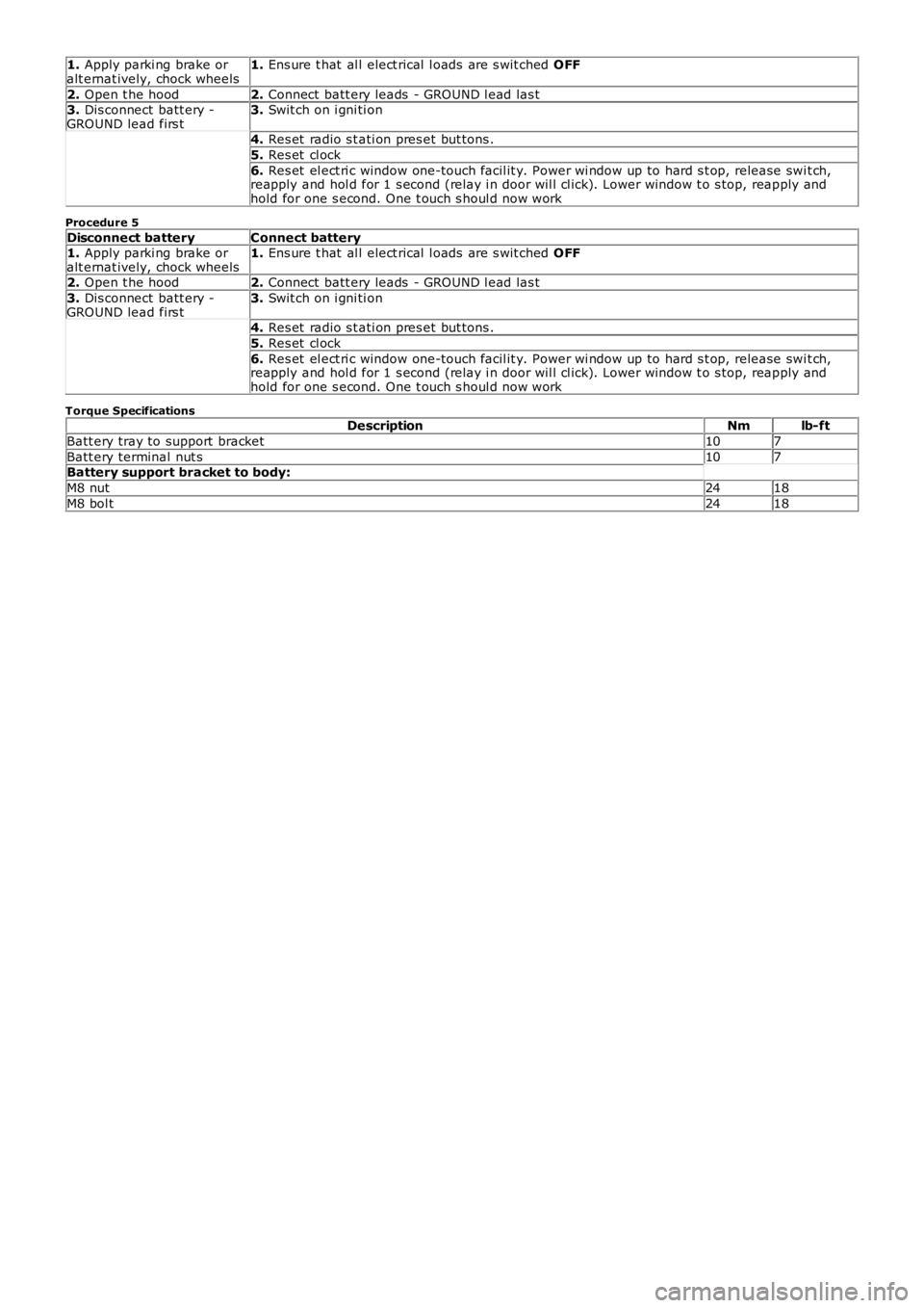
1. Apply parki ng brake oralt ernat ively, chock wheels1. Ens ure t hat al l elect rical l oads are s wit ched OFF
2. Open t he hood2. Connect batt ery leads - GROUND l ead las t3. Dis connect batt ery -GROUND lead firs t3. Swit ch on i gni ti on
4. Res et radio s t ati on pres et but tons .
5. Res et cl ock
6. Res et el ect ri c window one-touch facil it y. Power wi ndow up to hard s t op, release swit ch,reapply and hol d for 1 s econd (relay i n door wil l cl ick). Lower window t o s top, reapply andhold for one s econd. One t ouch s houl d now work
Procedure 5
Disconnect batteryConnect battery1. Apply parki ng brake oralt ernat ively, chock wheels1. Ens ure t hat al l elect rical l oads are s wit ched OFF
2. Open t he hood2. Connect batt ery leads - GROUND l ead las t
3. Dis connect batt ery -GROUND lead firs t3. Swit ch on i gni ti on
4. Res et radio s t ati on pres et but tons .
5. Res et cl ock
6. Res et el ect ri c window one-touch facil it y. Power wi ndow up to hard s t op, release swit ch,reapply and hol d for 1 s econd (relay i n door wil l cl ick). Lower window t o s top, reapply andhold for one s econd. One t ouch s houl d now work
Torque SpecificationsDescriptionNmlb-ft
Batt ery tray to support bracket107
Batt ery terminal nut s107Battery support bracket to body:
M8 nut2418
M8 bol t2418