2006 LAND ROVER FRELANDER 2 relay
[x] Cancel search: relayPage 2180 of 3229
3
-Seat heati ng module
Dependi ng on vehi cl e s peci fi cat ion, seat heati ng is avail abl e for bot h t he manual ly operat ed and t he power operat ed
s eat s . A heati ng element is incorporated wit hi n each s eat cus hi on and s quab. A seat heati ng modul e and elect rical wiring
is locat ed beneat h each front seat .
The s eat heat ing modules are connected on the LIN bus t o t he ATC, and are als o hardw ired to the AJB for the power
s uppl y. A ground t ermi nal from each s eat heat ing modul e completes the circui t.
For addit ional informat ion, refer t o: Cont rol Component s (412-01 Cli mat e Cont rol , Descripti on and Operat ion).
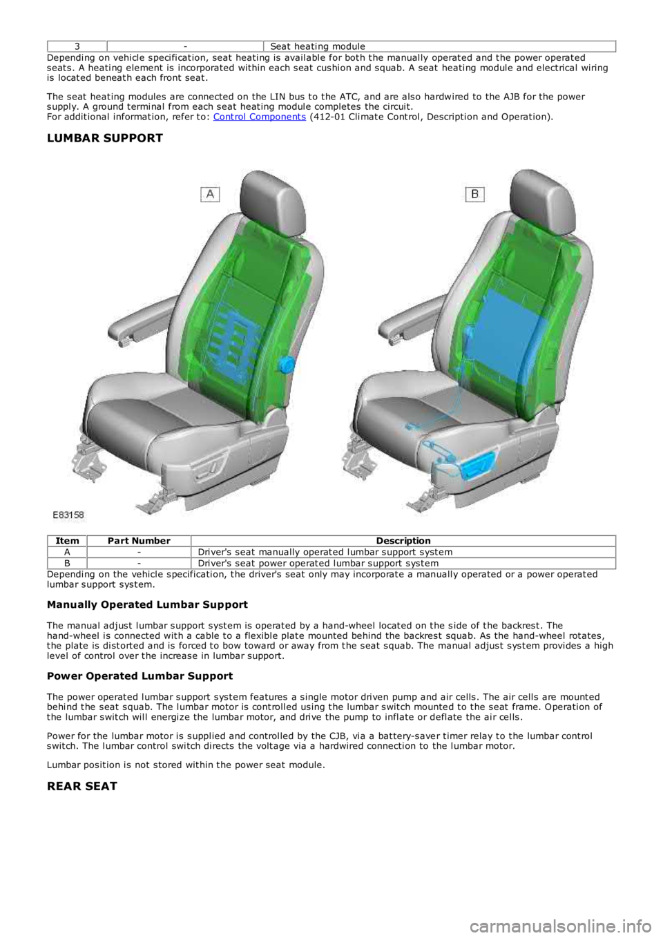
LUMBAR SUPPORT Item
Part Number Description
A -Dri ver's s eat manually operat ed l umbar s upport s yst em
B -Dri ver's s eat power operat ed l umbar s upport s ys t em
Dependi ng on the vehicl e s pecificati on, t he driver's seat only may incorporat e a man uall y operated or a power operat ed
lumbar s upport s ys t em.
Manually Operated Lumbar Sup port
The manual adjus t l umbar s upport s yst em is operat ed by a hand-wheel locat ed on t he s ide of t he backres t . The
hand-wheel i s connected wit h a cable t o a flexibl e plat e mounted behind the backres t squab. As the hand-wheel rot ates ,
t he plate is di st ort ed and is forced t o bow toward or away from t he s eat s quab. The manual adjus t s ys t em provi des a high
level of control over t he increas e in lumbar s upport.
Power Operated Lumbar Support
The power operat ed l umbar s upport s ys t em features a s ingle motor dri ven pump and air cells . The air cell s are mount ed
behi nd t he s eat s quab. The l umbar motor is cont roll ed us ing t he lumbar s wit ch mounte d t o t he s eat frame. O perati on of
t he lumbar s wit ch wil l energi ze the lumbar motor, and dri ve the pump to infl ate or d efl ate the ai r cel ls .
Power for the lumbar motor i s s uppl ied and control led by the CJB, vi a a bat tery-s ave r t imer relay t o t he lumbar cont rol
s wit ch. The l umbar control swi tch di rects the volt age via a hardwired connecti on to the l umbar motor.
Lumbar pos it ion i s not s tored wit hin t he power seat module.
REAR SEAT
Page 2182 of 3229
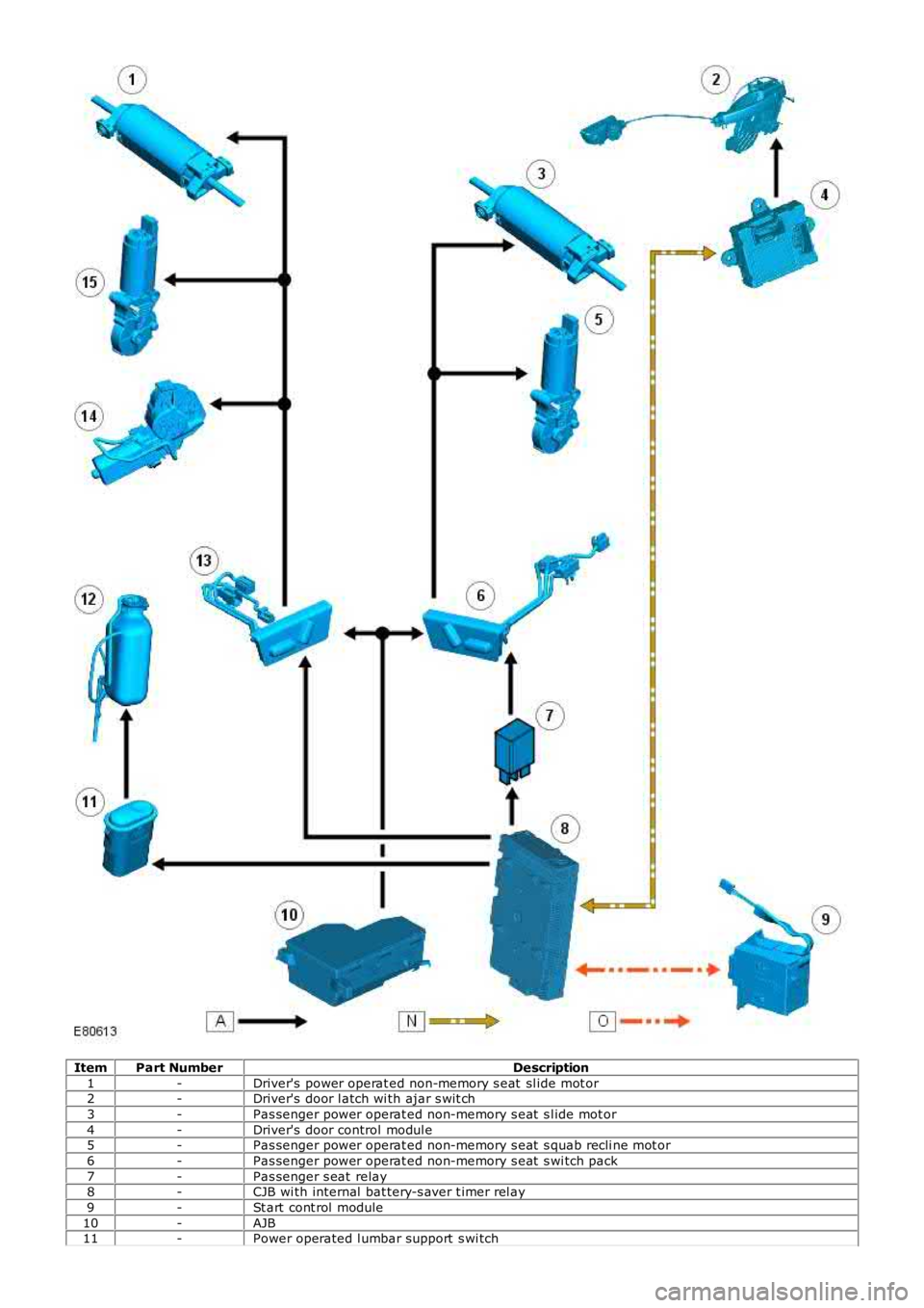
Item
Part Number Description
1 -Driver's power operat ed non-memory s eat sl ide mot or
2 -Driver's door l atch wi th ajar s wit ch
3 -Pas senger power operat ed non-memory s eat s l ide mot or
4 -Driver's door control modul e
5 -Pas senger power operat ed non-memory s eat s quab recli ne mot or
6 -Pas senger power operat ed non-memory s eat s wi tch pack
7 -Pas senger s eat relay
8 -CJB wi th internal bat tery-s aver t imer rel ay
9 -St art cont rol module
10 -AJB
11 -Power operated l umbar support s wi tch
Page 2184 of 3229
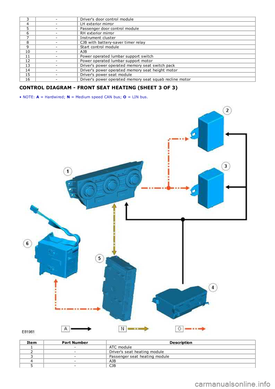
3
-Driver's door control modul e
4 -LH ext erior mirror
5 -Pas senger door control modul e
6 -RH ext eri or mirror
7 -Inst rument clus t er
8 -CJB wi th bat tery-s aver t imer relay
9 -St art cont rol module
10 -AJB
11 -Power operated l umbar support s wi tch
12 -Power operated l umbar support mot or
13 -Driver's power operat ed memory s eat s wi tch pack
14 -Driver's power operat ed memory s eat hei ght mot or
15 -Driver's power s eat module
16 -Driver's power operat ed memory s eat s quab recli ne mot or
CONTROL DIAGRAM - FRONT SEAT HEATING (SHEET 3 OF 3)
• NOTE: A = Hardwi red; N = Medium s peed CAN bus; O = LIN bus . Item
Part Number Description
1 -ATC modul e
2 -Driver's s eat heat ing module
3 -Pas s enger s eat heat ing module
4 -AJB
5 -CJB
Page 2185 of 3229
6
-St art control modul e
PRINCIPLES OF OPERATION
Front Power Operated Non-Memory Seats
The dri ver's non-memory s eat wil l operate i n all i gni ti on power modes . The pas senger non-memory seat wi ll only operat e
when t he ignit ion i s i n power mode 6 (Ignit ion).
Power for front pas s enger s eat operat ion is s upplied from t he AJB via a pas s enger s e at power relay t o t he pas s enger s eat
cont rol s wit ch pack. Power for t he driver's s eat operat ion is s upplied di rectl y from the AJB t o t he dri ver's s eat cont rol
s wit ch pack. The front pas s enger and dri ver s eat power suppli es are controlled by th e CJB. The s eat s wi tch pack direct s the
volt age to t he relevant s eat adjus tment mot or when a s eat control swit ch is pres s ed. Two pins wi thin each of t he s eat
s wit ch packs cont rol t he s eat motors. Bot h pins are normal ly connect ed to ground.
The dri ver and pas senger s wit ch packs are al s o connected i n circui t wit h a bat tery-s aver t imer relay t hat i s located in, and
cont rol led by t he CJB. The bat tery-s aver t imer relay all ows operati on of the driver and pas s enger s eat cont rols for 10
mi nut es aft er the engine is s wit ched off, and the i gni ti on is then s elected t o an ap propriat e power mode. The 10 minute
t imer is res et if t he appropriat e i gni ti on power mode is retai ned and the driver's d oor i s opened or clos ed. The driver and
pass enger s eat operati on is inhibit ed i mmediat el y fol lowi ng cent ral locking of t he v ehi cl e.
Operat ing a seat mot or control swit ch appli es volt age to one of t he pins whi le t he o t her pi n remai ns connect ed t o ground.
Operat ing t he s eat motor cont rol s wit ch in the oppos it e direct ion reverses the power and ground connecti ons to the mot or,
all owing t he mot or pi ni on t o rot ate in t he oppos i te di recti on. In t he event t hat a m ot or sei zes or s t icks , an i nternal
t hermal cut -out s wit ch wil l trip to remove volt age from t he mot or.
Driver's Power Operated Memory Seat
The dri ver's memory s eat wil l operat e when t he i gni ti on is in power modes 4 (Acces so ry) and 6 (Ignit ion), and wi ll not
operate during power mode 9 (Engine crank).
Power for the driver's memory s eat operat ion i s s uppl ied di rectl y from t he AJB t o t h e power s eat module. The memory s eat
s wit ch pack i s connected t o t he power seat module that cont rol s t he operati on and me mory pos it ion of t he i ndi vi dual s eat
mot ors . The power s eat module i s connected on the medi um s peed CAN bus t o t he CJB an d the front LH and RH door
cont rol modules .
The power seat module is als o connect ed in ci rcuit wi th a batt ery-saver ti mer rel ay that is locat ed wi thin, and controlled by
t he CJB. The batt ery-saver ti mer rel ay allows operat ion of t he s eat cont rols for 10 mi nut es aft er the engine is s wi tched off,
and t he ignit ion i s t hen sel ect ed to an appropri at e power mode. The 10 minut e t imer i s res et if t he appropri at e i gni ti on
power mode is retai ned and the driver's door i s opened or clos ed. The driver's s eat operat ion is i nhi bit ed immedi ately
fol lowing cent ral locki ng of the vehicl e.
Reques t s for memory exterior mirror movements for a memory recal l are t rans mit ted on the medi um s peed CAN bus by t he
power seat module to t he front door control modul es. The front door cont rol modules direct ly control the memory s t ore and
recall pos it ions for t he memory ext eri or mirrors.
For addit ional informat ion, refer t o: Rear Vi ew Mi rrors (501-09 Rear View Mirrors , Des cript ion and Operat ion).
Power Seat Mod ule
The power seat module features driver s electable funct ions , and aut omat ic monit ori ng functi ons .
Driver Selectable Functions
Seat and ext erior mirror memory recall Immediat e s eat adjus t ment.
Seat and exterior mirror memory recall function
The memory recall functi on s ets t he driver's seat t o a s t ored pos it ion, and is acti v at ed when a swi tch pack memory
posi ti on butt on is pres sed. W hen memory recal l i s i ni ti ated, only 2 seat adjus tment mot ors wil l operat e at any one t ime to
li mit the overall current cons umpti on. To furt her minimize t he current l oad as the m otors energize, the i nit iati on of each of
t he 2 operati ng mot ors i s phas ed wi th a 10 mill is econd del ay. The cushi on s lide and backres t wil l move fi rs t , foll owed by
t he cus hion height .
As s oon as t he seat s wit ch pack memory pos it ion but ton is pres s ed, a mes sage i s t ran s mit ted by the power s eat modul e
on t he medium s peed CAN bus to the front door control modul es. The door cont rol modu les t hen act ivat e t he memory
recall pos it ions for t he exteri or mirrors. The i nst rument clus t er mess age cent er wil l di s pl ay memory recall mes s ages when
a memory recall i s acti vat ed.
The memory recall functi on operates wit h 2 s eparate modes; t he operat ion of each mod e is dependant on t he vehicle
s tat us when the seat memory posi ti on butt on is pres sed.
Memory recall operati ng modes:
One-t ouch mode Proport ional mode.
One-Touch Mode
W hen t he vehicle i s s tat ionary and a s wit ch pack memory pos it ion butt on i s pres sed, t he memory recall functi on wil l
operate in 'one-touch' mode. One t ouch mode all ows the seat and exterior mirrors t o immediatel y move t o t he request ed
s tored memory pos i ti on.
If a s eat adjus t ment or memory pos it ion but ton i s operat ed during memory recal l 'one -t ouch' mode, t he current memory
recall wi ll be cancell ed and t he seat (and ext eri or mirrors via t he medium s peed CAN bus) wi ll i mmediat el y s top movi ng.
The s eat will t hen commence movi ng in the di recti on that corresponds to the press ed s wi tch.
Page 2349 of 3229
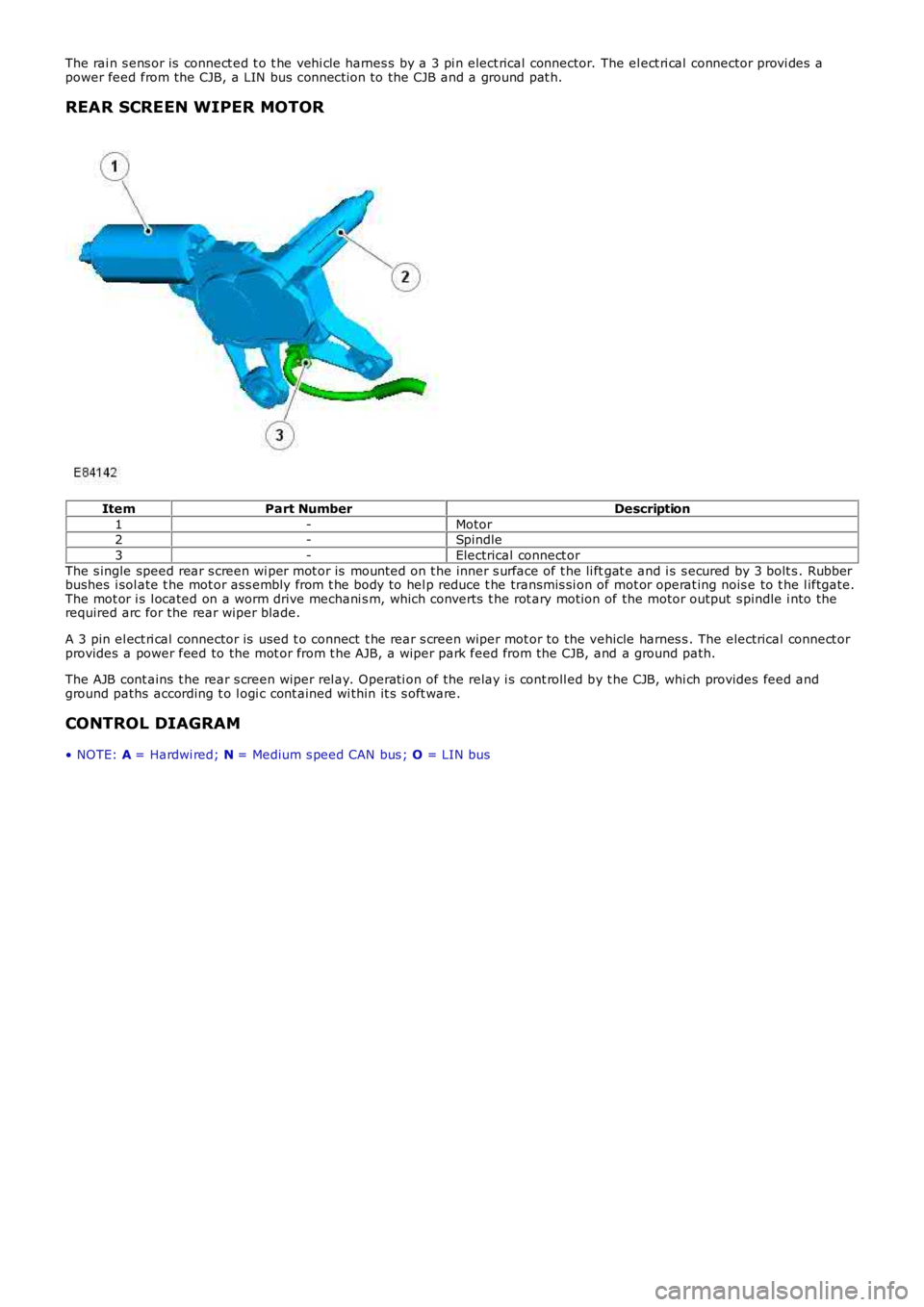
The rai n s ens or is connect ed t o t he vehi cl e harnes s by a 3 pi n elect rical connector. The el ect ri cal connector provi des apower feed from the CJB, a LIN bus connecti on to the CJB and a ground pat h.
REAR SCREEN WIPER MOTOR
ItemPart NumberDescription
1-Motor2-Spindle
3-Electrical connect or
The s ingle speed rear s creen wi per mot or is mount ed on t he inner s urface of t he li ftgat e and i s s ecured by 3 bolt s . Rubberbushes i sol ate t he mot or ass embly from t he body to hel p reduce t he transmis si on of mot or operat ing nois e to t he l iftgate.The mot or i s l ocated on a worm drive mechani s m, which converts t he rot ary moti on of the motor output s pindle i nto therequired arc for the rear wiper blade.
A 3 pin el ect ri cal connector is used t o connect t he rear s creen wiper mot or to the vehicle harnes s . The electrical connect orprovides a power feed to the mot or from t he AJB, a wiper park feed from the CJB, and a ground path.
The AJB cont ains t he rear s creen wiper rel ay. O perati on of the relay i s cont roll ed by t he CJB, whi ch provides feed andground paths according t o l ogi c cont ained wi thin it s s oft ware.
CONTROL DIAGRAM
• NOTE: A = Hardwi red; N = Medium s peed CAN bus ; O = LIN bus
Page 2351 of 3229
12-BJB
PRINCIPLES OF OPERATION
The wiper and was her s ys tem can operate i n a number of different ways when t he vehi cle i s in power mode 4 through 8.Reques t s from t he RH st eering col umn mult i-functi on s wit ch are trans mi tt ed over t he LIN bus t o the CJB, which i s t he maincont rol ler for t he s ys t em.
Windshield Wiper Slow Wipe
On recei vi ng a reques t for s low winds hield wiper operati on the CJB will energi ze relay 11 in t he BJB. W hen energized, relay11 provides a feed t o t he s wit ch cont act s of rel ay 8, whi ch is al so located i n t he CJB. Relay 8 is t he fast /s l ow wi pe relay.W hen s l ow wipe has been reques t ed relay 8 remai ns de-energized, allowi ng a feed to fl ow acros s the relay s wi tch contactst o the winds hi eld wi per motor s low speed brus h contacts .
Windshield Wiper Fast Wipe
On recei vi ng a reques t for fast windshi el d wi per operat ion t he CJB wi ll energize relay 11 and relay 8 i n t he BJB. W henenergized, relay 11 provides a feed to the s wi tch contacts of relay 8. The energized rel ay 8 provi des a feed t o t hewinds hield wiper mot or fast speed brus h contacts .
Windshield Wiper Intermittent Wipe
On recei vi ng a reques t for i ntermit tent wi nds hield wiper operati on, t he CJB wi ll energize relay 11 i n t he BJB to operat e t hewipers at s low s peed. Software cont ained wi thin the CJB i nterprets the t ime delay reques ted and controls operat ion ofrel ay 11 accordi ngl y.
The int ermi tt ent wiper s et t ing broadcast on the LIN bus t o t he CJB equat es to the followi ng t ime del ays .
LIN Bus SignalT ime Delay (seconds)
122
215.539.5
46
53.561
In the event of a LIN bus fai lure bet ween t he CJB and the RH s teeri ng col umn mul ti -funct ion s wi tch, the CJB wi ll default to'Limp Home' mode (see bel ow).
Windshield Wiper Automatic Wipe
On recei vi ng a reques t for aut omat ic winds hi eld wi per operat ion, t he CJB int erpret s LIN bus mess ages received from therai n s ens or. The rain sens or provides LIN bus mess ages wit h values rangi ng from 0 to 7. A s ignal val ue of 0 is interpretedby t he CJB as there being no wat er on the windshi eld.
A s i gnal value from 1 t o 5 i s int erpret ed by t he CJB as there being a smal l amount of wat er hi tt ing the wi nds hiel d. In t hisins t ance, the CJB i nit iates a s low wipe rout ine as det ailed in t he 'W inds hield W iper Slow W i pe' s ect ion above.
A s i gnal value from 6 t o 7 i s int erpret ed by t he CJB as there being a large amount of water hi tt ing t he wi nds hield. In t hisins t ance, the CJB i nit iates a fas t wi pe routi ne as detai led i n t he 'W i ndshi el d W iper Fas t W i pe' s ecti on above.
Rain s ens or s ens it ivit y can be adjus ted by turni ng t he rot ary control on the RH st eeri ng col umn mul ti -funct ion s wit ch t ot he required pos i ti on. Si x different s ensi ti vi ty set ti ngs are avail abl e, which are broadcas t over t he LIN bus to the CJB.
• NOTE: The CJB wil l onl y change a fas t wipe routi ne t o a s low wipe routi ne if t he rai n s ens or value i s lower t han 4.
Windshield Wiper Flick Wipe
On recei vi ng a reques t for fli ck wipe operat ion t he CJB wil l operate t he wi nds hiel d wipers as described in the 'Slow W ipe's ect ion above unti l the reques t is removed.
Windshield Wiper Park
The winds hield wiper park s wi tch i s int egral wit h t he winds hi eld wiper motor. The park s wit ch ensures the windshi el dwipers ret urn t o t he park pos it ion if t he winds hi eld wiper reques t i s cancell ed mid-s troke.
The CJB is connect ed t o one s ide of t he park s wit ch. The park s wit ch cont act s are open when the wi pers are in any pos it ionexcept t he park pos it ion. W hil e t he s wit ch cont act s are open, the CJB conti nues to energi ze rel ays 11 and 8 in the BJB,even if a LIN bus s ignal has been recei ved from t he RH s t eering column mult i-functi on s wit ch request ed t he wipers ares topped.
W hen t he wi pers reach t he park pos it ion, the park s wit ch cont act s clos e and a ground pat h i s created. W hen t he CJBregi st ers t his ground pat h i ts software logic det ermi nes the wipers are i n the park posi ti on and de-energi zes relays 11 and8 i n t he BJB.
Windshield Wiper Limp Home Mode
In the event of a LIN bus fai lure bet ween t he CJB and the RH s teeri ng col umn mul ti -funct ion s wi tch when t he wi nds hieldwipers are act ive, the CJB wi ll enter l imp home mode. In limp home mode, t he CJB will onl y power t he wi nds hiel d wipersat s low s peed.
Windshield Wiper Service Position
The winds hield wipers can be parked on the winds hi eld t o ai d the fi tment of new wi per bl ades . For more i nformati on, refer
Page 2352 of 3229
t o the 'Owners Handbook'.
Rear Screen Wiper
On recei vi ng a reques t for rear s creen wi per operat ion the CJB wi ll energize relay RA2 i n t he AJB. W hen energized, relayRA2 provides a feed t o t he rear s creen wiper mot or. The rear s creen wi per operat es int ermi tt entl y, wi th a delay betweenwipes of approximat ely 6 seconds . The CJB cont rol s operati on of rel ay RA2, and consequentl y rear s creen wiper mot oroperati on, accordingly.
The CJB als o provi des a feed t o t he rear s creen wi per mot or park s wit ch. The park s wit ch is i ntegral wi th the rear s creenwiper mot or and ens ures t he wi per returns to the park pos i ti on if t he rear wi per reques t is cancel led mid-st roke. The parks wit ch cont act s are cl osed when the rear wiper is i n any posi ti on except t he park pos it ion. Thi s all ows the CJB to returnt he rear wiper t o t he park pos it ion when relay RA2 i s de-energized.
The CJB wil l als o power the rear screen wiper motor i f revers e gear is s elected whi le the wi nds hiel d wi per funct ion i sact ive. On vehicles fit t ed wit h an aut omat ic trans mi s si on, t he reverse gear s ignal origi nat es in the Transmis si on ControlModule (TCM). The TCM broadcas ts a revers e gear s ignal over the hi gh s peed CAN bus to the CJB, which responds byoperati ng t he rear wiper.
On vehicles fit ted wit h a manual transmis s ion, the revers e gear s i gnal ori ginates at t he revers e gear s wit ch. The reversegear s wi tch i s hardwired t o t he CJB.
Windshield Washers
On recei vi ng a reques t for wi nds hiel d was her operat ion t he CJB wi ll energize t he front washer cont rol relay. Thi s all ows abatt ery volt age feed t o flow to the was her pump. A ground path for t he pump is provided by t he de-energized rear was hercont rol rel ay. Bot h was her control relays are int egral wit h t he CJB.
W hen wi ndshi el d was her operat ion i s reques ted, t he winds hi eld was hers will operat e. The CJB will delay wiper operati onfor 100 ms aft er the was her swi tch i s pres s ed. If t he s wit ch is pres s ed for l ess than 100 ms, t he CJB wil l not operat e t hewipers.
The CJB wil l power t he wi nds hield wipers for as l ong as washer operati on is reques t ed, al though t he washers wil l ti me outaft er 10 s econds. After t he was her s wi tch has been rel eas ed, the CJB wi ll operat e t he winds hi eld wipers t hrough 2 morewipe cycles .
Rear Screen Washer
On recei vi ng a reques t for rear s creen was her operati on the CJB wi ll energize the rear was her cont rol rel ay. This al lows abatt ery volt age feed t o flow to the was her pump. A ground path for t he pump is provided by t he de-energized front was hercont rol rel ay. Revers ing the polarit y of the pump (s ee 'W i nds hield W as hers ' above) allows was her fl uid t o be di rected t ot he rear s creen washer jet rather t han the windshi el d was her jets . The rear s creen was her jet is incorporat ed int o the hi ghmounted s t op lamp.
The rear s creen was her wi ll operat e for up t o 10 seconds if cont inuousl y reques ted. W hen rear s creen was her operati on isreques ted, the rear screen wiper wil l operat e conti nuous ly unt il t he s wit ch is released. After t he swit ch has been released,or fol lowing 10 seconds of conti nuous operat ion, the CJB will operat e t he rear s creen wiper t hrough 2 or 3 more wi pecycles .
Headlamp Washers
W hen t he vehicle ent ers i gni ti on mode 4 (acces s ory) to 7 (engine running) the firs t winds hield was h reques t great er than100 ms will operat e a headlamp power was h s equence. The CJB will t hen s tart a 10 mi nut e t imer. If 5 request s forwinds hield washer operati on are made wit hin this 10 mi nut e wi ndow, t he CJB wil l power t he headl amp was hers uponreceiving the fifth reques t . W hen t his occurs , the 10 minute ti mer is res et t o 0.
If the CJB receives no windshi el d was her reques t s duri ng a 10 mi nute window, the headlamp was hers will operat e on t hefi rs t reques t received aft er the 10 minut e window has el aps ed. Agai n, once t he headlamp was hers have been operati onal ,t he CJB res ets t he t imer t o 0.
The headl amp was hers wi ll only operat e when t he headl amps are on. The CJB receives a 'li ght s on' si gnal from the lightcont rol module over t he LIN bus .
W hen headlamp was her operati on is required, t he CJB energizes rel ay 9 in the BJB, all owing a bat tery vol tage feed t opower the headlamp was her pump. A ground path for t he washer pump i s provided by t he de-energi zed relay 12, which i sals o l ocat ed in the BJB. Thi s s equence of event s provides was her flui d t o the headlamp 1 was her jets .
Aft er thi s s equence the power s uppl y t o t he pump is revers ed. The CJB does t his by de-energi zing rel ay 9 and energi zi ngrel ay 12. Thi s allows the pump to provi de was her flui d to the headlamp 2 was her jets. The s equence of event s runs asfol lows :
Power to headlamp 1 was her - 500 msDelay t o power headl amp 2 was her - 100 msPower to headlamp 2 was her - 500 msDelay (s oak ti me) to power 1 headlamp washer - 700 msPower to 1 headl amp was her - 500 msDelay t o power 2 headl amp was her - 100 msPower to 2 headl amp was her - 500 ms
If there is l ess than 1 l it er (0.26 US gall on) of was her flui d in the was her fl uid reservoi r, t he CJB wil l s us pend headl ampwas her operat ion. The fl uid l evel s wit ch is hardwired to the CJB, which als o t rans mits a low fl ui d s ignal to the i nst rumentclus ter over t he medi um s peed CAN bus. For addit ional i nformati on, refer to:
Ins trument Clus ter (413-01 Ins t rument Clus t er, Descripti on and Operat ion),Informat ion and Mes s age Cent er (413-08 Informati on and Mes sage Cent er, Descripti on and Operat ion).
Page 2353 of 3229
Publi s hed: 11-May-2011
Wipers and Washers - Wipers and Washers
Diagnosi s and Tes ti ng
Principles of Operation
For a detail ed descripti on of the wiper and washer s yst ems , refer t o t he rel evant De s cript ion and Operat ion secti on in the
works hop manual .
REFER to: W ipers and W ashers (501-16 W i pers and W as hers , Descripti on and Operat ion).
Inspection and Verification CAUTION: Di agnos is by s ubs ti tut ion from a donor vehicle is
NO T acceptabl e. Subs ti tut ion of cont rol modules does
not guarant ee confirmat ion of a faul t, and may als o caus e addit ional fault s i n t he v ehi cl e being t est ed and/or t he donor
vehi cl e.
1. Verify t he cus t omer concern.
1.
2. Vis ually ins pect for obvious s igns of mechani cal or electrical damage.
2.
Visual Inspection Mechanical Electrical
W iper bl ades W iper pi vot arm shaft
W as her res ervoir
Hos e(s )
W as her jet (s ) Fus es /rel ays (refer t o electrical gui de)
W iring harnes s
Correct engagement of electrical connect ors
Loos e or corroded connect ions
3.
If an obvious cause for an obs erved or report ed concern is found, correct t he caus e (if pos s ible) before
proceeding t o t he next s t ep.
3.
4. If t he caus e is not vis ually evi dent , check for Di agnos ti c Trouble Codes (DTCs) and refer t o t he DTC Index.
4.
DTC Index
• NOTE: If the control modul e or a component i s s us pect and the vehicle remains unde r manufacturer warrant y, refer t o the
W arranty Pol icy and Procedures manual (s ect ion B1.2), or determine i f any pri or appr oval programme is in operat ion, pri or
t o the ins tall ati on of a new module/component.
• NOTE: Generic scan t ool s may not read the codes li st ed, or may read only fi ve digi t codes . Mat ch the five di git s from t he
s can tool to the firs t fi ve di git s of the seven digi t code l is ted to ident ify t he fa ul t (t he las t t wo digi ts gi ve ext ra
informat ion read by the manufact urer-approved diagnost ic s ys tem).
• NOTE: W hen performing volt age or res is t ance t est s , always use a digi tal mult imeter (DMM) accurat e t o t hree deci mal
places and wit h a current cal ibrat ion cert ificate. W hen tes ti ng res i st ance, always t ake the res is tance of the DMM l eads i nto
account.
• NOTE: Check and recti fy bas ic faul ts before beginni ng diagnos t ic rout ines i nvol vi n g pinpoint t es t s.
• NOTE: If DTCs are recorded and, aft er performi ng the pi npoi nt tes ts , a fault is no t present , an int ermi tt ent concern may
be t he caus e. Always check for loose connect ions and corroded terminals .
DT C Description Possible Cause Action
B109512 W iper On/O ff Relay - circui t
s hort t o power W i per On/Off relay ci rcuit -
s hort t o power Refer to el ect ri cal circui t diagrams and
check wiper On/O ff rel ay circuit for s hort to
power
B109514 W iper On/O ff Relay - circui t
s hort t o ground or open W i per On/Off relay ci rcuit -
s hort t o ground, open ci rcuit Refer to el ect ri cal circui t diagrams and
check wiper On/O ff rel ay circuit for s hort to
ground, open circui t
B109612 W iper High/Low Relay - circui t
s hort t o power W i per High/Low relay circui t -
s hort t o power Refer to el ect ri cal circui t diagrams and
check wiper High/Low rel ay ci rcuit for short
to power
B109614 W iper High/Low Relay - circui t
s hort t o ground or open W i per High/Low relay circui t -
s hort t o ground, open ci rcuit Refer to el ect ri cal circui t diagrams and
check wiper High/Low rel ay ci rcuit for short
to ground, open circuit
B10AD04 Rai n Sens or - Syst em Int ernal
Fail ure Int ernal s ens or fai lure Ins tal l a new rai n s ensor.
REFER t o: Rain Sens or (501-16 W ipers and
W as hers, Removal and Ins t al lat ion).
B10AD09 Rai n Sens or - Component
Fail ures Rain sens or incorrectl y
ins t al led Rain sens or internal failure Check for correct i nst all ati on of rain
sens or. Ins t all a new sens or as required.
REFER t o: Rain Sens or (501-16 W ipers and
W as hers, Removal and Ins t al lat ion).
B113188 W iper Motor Module - Bus off Lost communi cat ions wit h
wi per mot or modul e Carry out di agnos ti c s trat egy as sociat ed
wit h t hi s DTC us ing manufact urer approved
di agnos ti c s yst em
B1C8212 Headlamp W as her Rel ay Coi l
Ci rcuit - circui t s hort t o power Headlamp was her relay control
circui t - short to power Refer to el ect ri cal circui t diagrams and
check headl amp was her relay cont rol circui t
for s hort to power