2006 LAND ROVER FRELANDER 2 light
[x] Cancel search: lightPage 588 of 3229
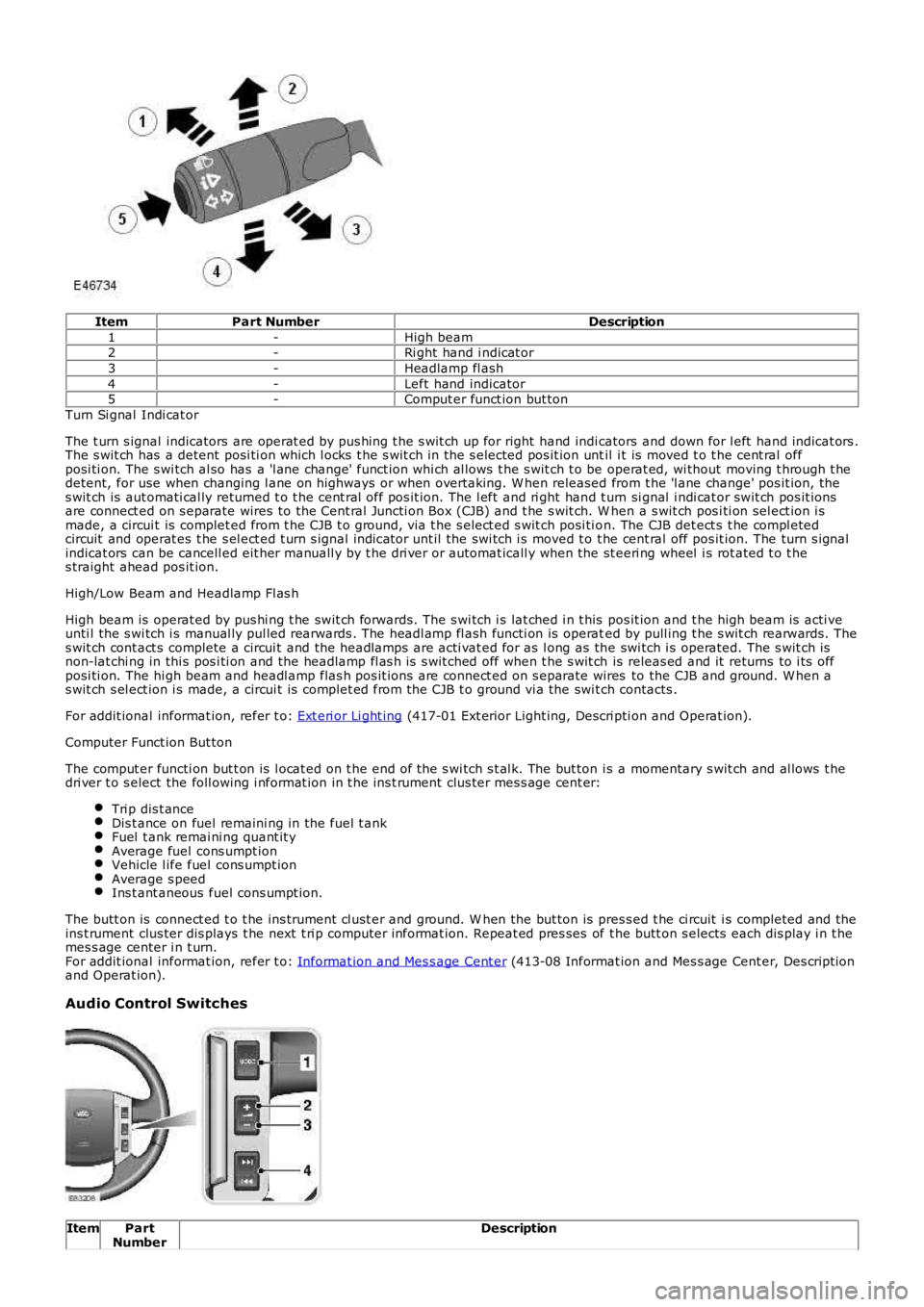
ItemPart NumberDescription
1-High beam2-Ri ght hand i ndicat or
3-Headlamp fl ash
4-Left hand indicator5-Comput er funct ion but ton
Turn Si gnal Indi cat or
The t urn s ignal indicators are operat ed by pus hing t he s wit ch up for right hand indicators and down for l eft hand indicat ors .The s wit ch has a detent posi ti on which l ocks t he s wit ch in the s elected pos it ion until i t is moved t o t he cent ral offposi ti on. The s wi tch al so has a 'l ane change' funct ion whi ch al lows t he s wit ch t o be operat ed, wi thout moving t hrough t hedetent, for use when changing l ane on highways or when overtaking. W hen released from t he 'l ane change' pos it ion, thes wit ch is aut omati cal ly returned t o t he cent ral off pos it ion. The l eft and ri ght hand t urn si gnal i ndi cat or swit ch pos it ionsare connect ed on s eparate wires to the Cent ral Juncti on Box (CJB) and t he s wit ch. W hen a s wit ch pos i ti on sel ect ion i smade, a circui t is complet ed from t he CJB t o ground, vi a t he s elect ed s wit ch posi ti on. The CJB det ect s t he compl etedcircuit and operat es t he s el ect ed t urn s ignal indicator unt il the swi tch i s moved t o t he cent ral off pos it ion. The turn s ignalindicat ors can be cancell ed eit her manuall y by t he dri ver or automat icall y when t he st eeri ng wheel i s rot ated t o t hes traight ahead pos it ion.
High/Low Beam and Headlamp Fl as h
High beam is operat ed by pus hi ng t he swit ch forwards. The s wi tch i s lat ched i n t his pos it ion and t he high beam is acti veunti l the s wi tch i s manual ly pul led rearwards . The headl amp fl ash functi on is operated by pull ing t he s wit ch rearwards. Thes wit ch cont act s complete a circui t and the headlamps are acti vat ed for as l ong as the swi tch i s operated. The s wit ch isnon-lat chi ng in thi s pos i ti on and the headlamp fl as h is s wit ched off when t he s wit ch is releas ed and it returns to i ts offposi ti on. The hi gh beam and headl amp flas h pos it ions are connect ed on s eparate wires to the CJB and ground. W hen as wit ch s el ect ion i s made, a circui t is complet ed from the CJB t o ground vi a the swi tch contacts .
For addit ional informat ion, refer t o: Ext eri or Li ght ing (417-01 Ext erior Light ing, Descri pti on and Operat ion).
Computer Funct ion But ton
The comput er functi on but t on is l ocat ed on t he end of the s wi tch s t al k. The but ton is a momentary s wit ch and al lows t hedri ver t o s elect the foll owing i nformat ion in t he ins t rument clus ter mes s age cent er:
Tri p dis t anceDis t ance on fuel remaini ng in the fuel t ankFuel t ank remai ni ng quant it yAverage fuel cons umpt ionVehicle l ife fuel cons umpt ionAverage s peedIns t ant aneous fuel cons umpt ion.
The butt on is connect ed t o t he ins trument cl ust er and ground. W hen the but ton is pres s ed t he ci rcuit i s completed and theins t rument clus ter dis plays t he next t ri p computer informat ion. Repeat ed pres ses of t he butt on s elects each dis play i n t hemes s age center i n t urn.For addit ional informat ion, refer t o: Informat ion and Mes s age Cent er (413-08 Informat ion and Mes s age Cent er, Des cript ionand Operat ion).
Audio Control Switches
ItemPartNumberDescription
Page 606 of 3229
Cont rol Module (ECM) cont rols t he fuel injection s ys t em and t he ignit ion s yst em.
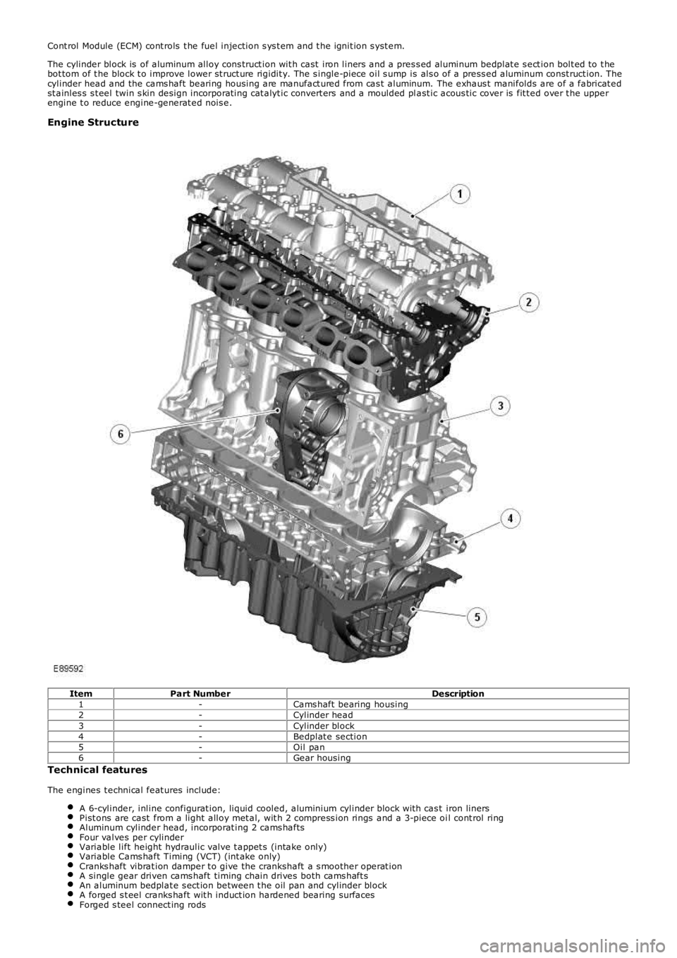
The cylinder block is of aluminum alloy cons truct ion wit h cast iron liners and a pres s ed aluminum bedplat e s ect ion bolt ed to t hebot tom of t he block t o improve lower st ruct ure rigidit y. The s ingle-piece oil s ump is als o of a press ed aluminum const ruct ion. Thecylinder head and the cams haft bearing housing are manufact ured from cas t aluminum. The exhaus t manifolds are of a fabricat edst ainles s s t eel twin s kin design incorporat ing cat alyt ic convert ers and a moulded plast ic acous tic cover is fit t ed over t he upperengine t o reduce engine-generat ed nois e.
Engine Structure
ItemPart NumberDescription1-Cams haft bearing housing2-Cylinder head3-Cylinder block4-Bedplat e section5-Oil pan6-Gear housing
Technical features
The engines t echnical feat ures include:
A 6-cylinder, inline configurat ion, liquid cooled, aluminium cylinder block wit h cast iron linersPist ons are cast from a light alloy met al, wit h 2 compress ion rings and a 3-piece oil cont rol ringAluminum cylinder head, incorporat ing 2 cams haftsFour valves per cylinderVariable lift height hydraulic valve t appet s (intake only)Variable Cams haft Timing (VCT) (int ake only)Cranks haft vibrat ion damper t o give the crankshaft a s moother operat ionA single gear driven cams haft timing chain drives both cams haft sAn aluminum bedplat e s ect ion between t he oil pan and cylinder blockA forged s t eel cranks haft wit h induct ion hardened bearing surfacesForged s teel connect ing rods
Page 609 of 3229
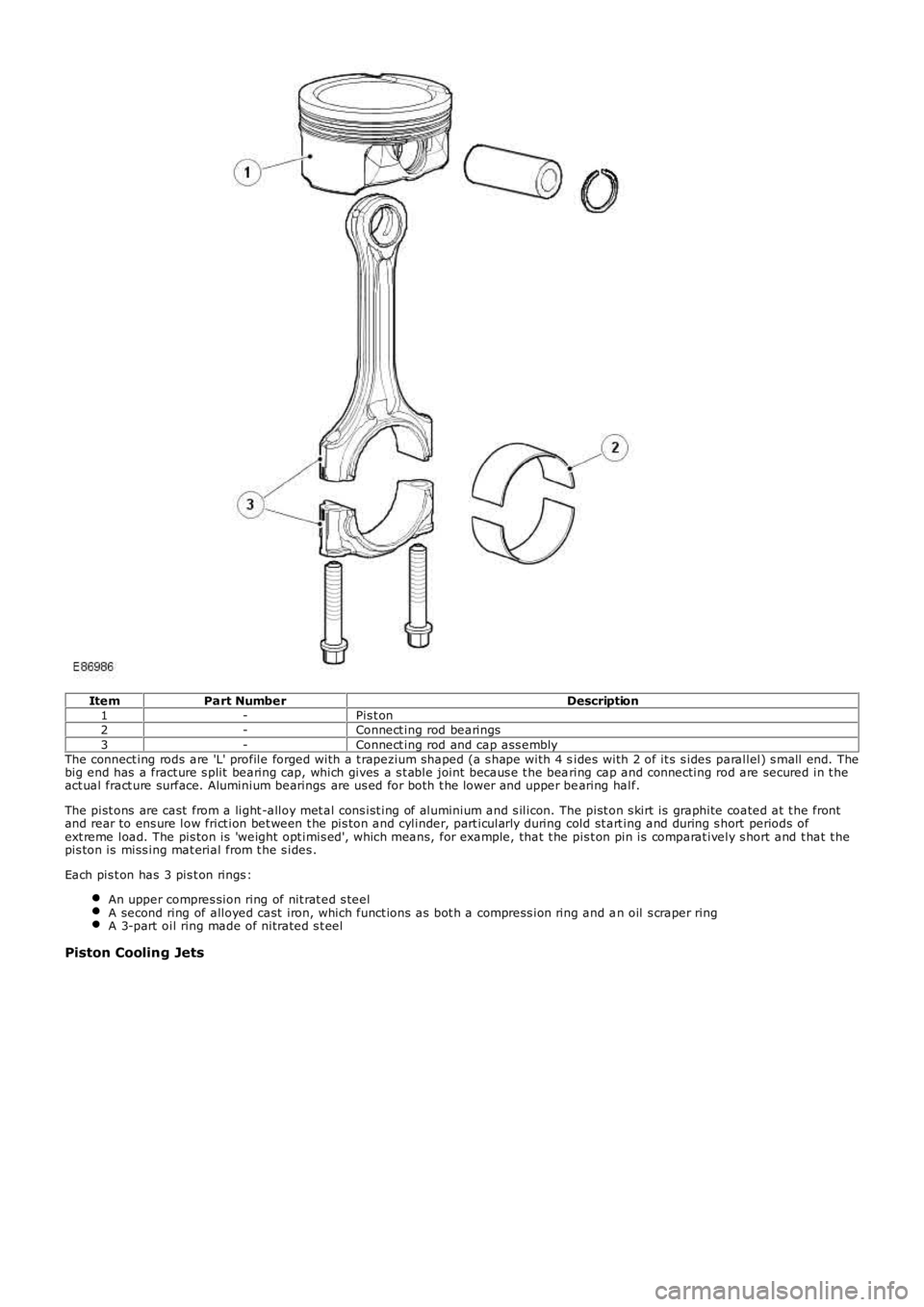
ItemPart NumberDescription1-Pis t on2-Connect ing rod bearings3-Connect ing rod and cap ass emblyThe connect ing rods are 'L' profile forged with a t rapezium shaped (a s hape with 4 sides with 2 of it s s ides parallel) s mall end. Thebig end has a fract ure s plit bearing cap, which gives a s t able joint becaus e t he bearing cap and connecting rod are secured in t heact ual fract ure surface. Aluminium bearings are us ed for both t he lower and upper bearing half.
The pist ons are cast from a light -alloy met al cons ist ing of aluminium and s ilicon. The pist on s kirt is graphite coated at t he frontand rear to ens ure low frict ion bet ween t he pis ton and cylinder, part icularly during cold st art ing and during s hort periods ofext reme load. The pis ton is 'weight opt imis ed', which means, for example, that t he pis t on pin is comparat ively s hort and t hat t hepis ton is miss ing mat erial from t he s ides .
Each pis t on has 3 pis t on rings :
An upper compres sion ring of nit rat ed s teelA second ring of alloyed cast iron, which funct ions as bot h a compress ion ring and an oil s craper ringA 3-part oil ring made of nitrated s t eel
Piston Cooling Jets
Page 617 of 3229

The chill cas t cylinder head is of t he cros s-flow t ype, manufact ured from a light-alloy met al. Deep-s eat ed bolt s, to reducedis tortion, s ecure t he cylinder head t o t he cylinder block. Two hollow locat ing dowels align the cylinder head wit h t he cylinderblock. The 2 cams haft s are supported by 7 bearing caps each, direct ly in t he cylinder head and cams haft cover.
Cylinder Head Gasket
ItemPart NumberDescription1-Cylinder head gasketThe s eal bet ween the cylinder head and cylinder block is a conventional cylinder head gas ket . The head gasket is made of s t eeland has multiple layers . For s ervice, t here is only 1 s iz e of gas ket available.
Oil Separation Housing
Page 619 of 3229
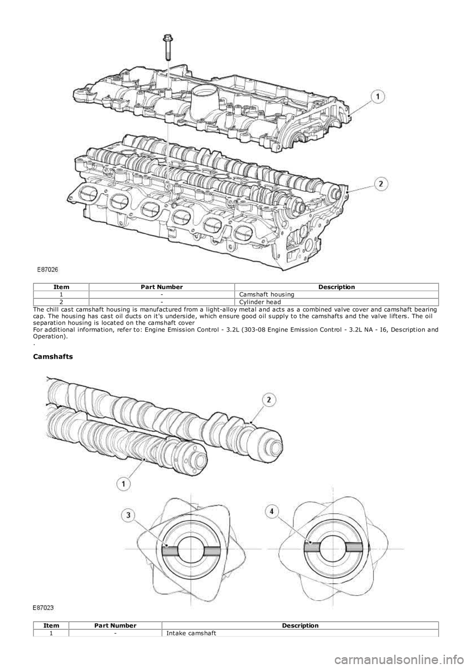
ItemPart NumberDescription1-Cams haft hous ing2-Cylinder headThe chill cas t cams haft hous ing is manufact ured from a light-alloy met al and act s as a combined valve cover and cams haft bearingcap. The hous ing has cas t oil duct s on it 's unders ide, which ensure good oil s upply t o t he camshaft s and t he valve lift ers . The oilseparat ion housing is locat ed on t he cams haft coverFor addit ional information, refer t o: Engine Emiss ion Cont rol - 3.2L (303-08 Engine Emis sion Cont rol - 3.2L NA - I6, Des cript ion andOperation)..
Camshafts
ItemPart NumberDescription1-Int ake cams haft
Page 733 of 3229
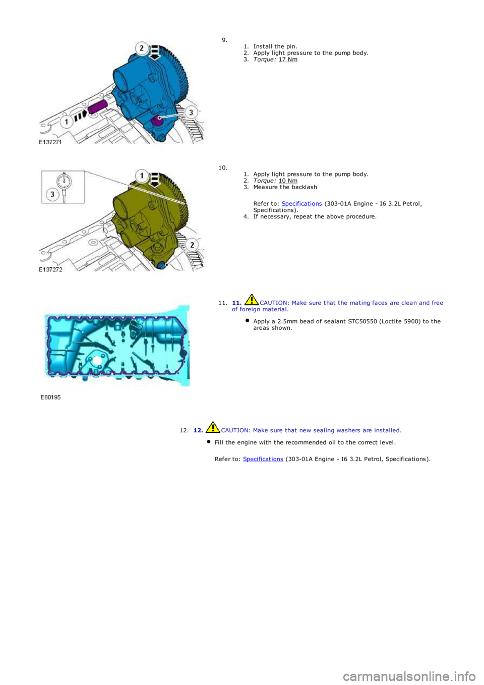
Ins t all t he pin.
1.
Apply light pres sure t o t he pump body.
2.
T orque : 17 Nm 3.
9.
Apply light pres sure t o t he pump body.
1.
T orque : 10 Nm 2.
Mea sure t he backl ash
Re fer t o: Specificat ions (303-01A Engine - I6 3.2L P et rol ,
Specificat ions).
3.
If ne ce ss ary, repe at t he above procedure.
4.
10. 11. CAUTION: Ma ke sure t hat t he ma t ing fa ces a re clea n and fre e
of foreign mat eria l.
Apply a 2.5mm be ad of se alant STC50550 (Loct it e 5900) t o t he
are as shown. 11.
12. CAUTION: Make s ure that ne w sea ling was hers are ins t alle d.
Fi ll t he e ngine wit h t he re commended oil t o t he correct le vel .
Refe r t o: Specificat ions (303-01A Engine - I6 3.2L P et rol, Specifica ti ons ).12.
Page 851 of 3229
2.
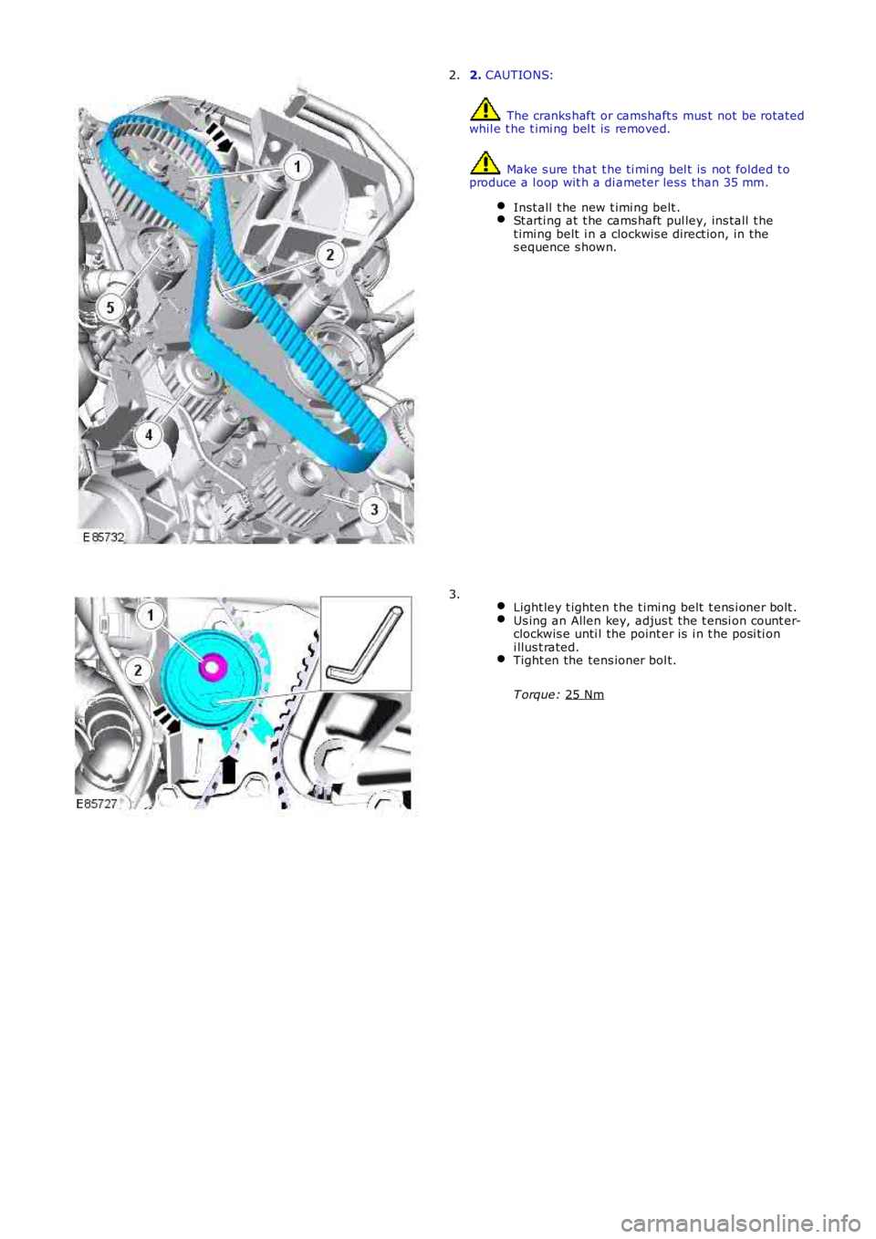
CAUTIONS: The cranks haft or camshaft s mus t not be rot ated
whil e t he t imi ng bel t is removed. Make s ure that t he ti mi ng bel t is not folded t o
produce a l oop wit h a di ameter les s t han 35 mm.
Inst all t he new t imi ng belt . St arti ng at t he cams haft pul ley, ins tall t he
t imi ng belt i n a clockwis e direct ion, in the
s equence s hown. 2.
Light ley t ighten t he t imi ng belt t ens i oner bolt . Us ing an Allen key, adjus t the t ensi on count er-
clockwis e unti l the point er is i n t he posi ti on
i llus t rated. Tight en the tens ioner bol t.
T orque: 25 Nm 3.
Page 1108 of 3229
however remain i ll uminated.
A ‘st all recovery’ event is the onl y s tat e when t he Stop/St art s yst em wil l permit t he engine t o be s t art ed when thet ransmis s ion i s in gear; hence t he requirement for t he cl utch pedal to be full y depres sed. If the s t all recovery fai ls and t heengi ne does not res tart, t he dri ver wi ll be reques ted vi a t he Mess age Center t o ‘s elect neutral ’ to at t empt anot her rest art .
If the engine does not res t art aft er thi s request t he ‘st all recovery’ mode wil l ti me-out and deact ivate. At t his point t he‘Eco’ i con in t he i ns t rument panel wi ll exti ngui sh and the light s usual ly as s ociat ed wi th an engi ne st all wi ll il lumi nat e. As ares ult t he dri ver will be requi red to perform a convent ional engi ne res tart.
Alt hough st all recovery i s a feat ure of t he St op/Start sys t em i t is pos si ble for it t o acti vat e i ndependent ly from t heStop/St art parameters . For exampl e:
If the St op/Start s ys t em has been deact ivated by the driver st all recovery wi ll s ti ll funct ion.Stal l recovery wil l act ivate at ambi ent temperat ures as l ow as (minus ) - 2°C, whereas the St op/Syst em operat ingt emperature threshold is above 4°C.Different t o t he operat ion of t he Stop/St art s yst em, s tal l recovery wil l st il l functi on when the vehicle is t owing;refer to the ‘Trail er Towi ng’ s ect ion.
• NOTE: As t he neces s ary cri teria will not have been sat is fi ed when t he vehi cl e i s at the beginning of a journey s t allrecovery wi ll not functi on. For exampl e, if t he vehi cl e s tal ls when l eavi ng the garage or driveway a convent ional engineres t art wi ll be required.
Trailer Towing
The Stop/St art s ys tem wil l aut omati cal ly di sabl e when t rail er light s are det ect ed by t he CJB via s ignals from t he t rail ermodule, t hi s informat ion i s t hen trans mi tt ed t o t he ECM. It i s not pos s ibl e for t he s ys t em t o det ect when a trai ler powerplug i s ins ert ed i n the vehicl e’s t owi ng s ocket s o it us es operat ion of t he trail er l ights as it s indi cat or.
The t rail er towing sys tem inhi bi ts St op/St art as i t is pos s ible that trail er power requirements could interfere wit h t heoperati on of the bat tery monit ori ng s ys t em. In parti cul ar, a t rai ler batt ery could revers e t he feed current t o t he vehicleduri ng an engi ne cranking event , t hi s coul d pos si bly:
Confus e t he bat t ery monit ori ng s ys t em i nto det ect ing an unreal is t ically smal l current at engi ne cranking.Rupture the fus e as sociat ed wit h t he t rail er modul e.
Climate Control System
• NOTE: The ‘ECON’ butt on has been renamed ‘A/C’ to prevent confus ion wi th the St op/St art s yst em ‘Eco’ s wit ch.
A number of changes have been made to the l ogi c and operati on of climat e control system, wit hi n a St op/St art cycle to:
maint ain occupant comfortprevent winds hi eld mis ti ngcons erve bat tery power.
This has been achi eved by the ATC (automat ic t emperat ure control) module monit oring and varyi ng, as necess ary variousclimate control funct ions wi thi n a St op/Start cycle.
In s ome circums t ances t he ATC has t he capabil it y to inhibit an engi ne s hut down or init iat e an engine rest art wit hi n aStop/St art cycle. Thi s i s achi eved by t he ATC module communi cat ing wit h t he CJB on the medi um s peed CAN. The variousoverri de functi ons the ATC has in a St op/St art cycl e are di s cus s ed bel ow:
Coolant temperat ure
The ATC module wil l i nhibit an engine shut down or i nit iat e an engine res t art wi thi n a St op/Start cycle if t he coolantt emperature fal ls below the calculat ed t hreshol d to s upport t he cabin t emperat ure s et by t he vehi cl e occupant s .
W i nds hiel d demis t ing
The variant of cli mate control fi tt ed t o the vehicl e influences t he s oft ware changes that have been made. For exampl e, thebase cl imat e-control s ys tem does not have a humi dit y s ens or, as us ed on a highline sys tem t o ini ti at e a winds hi elddemis t . Therefore, a calculat ion for demis ti ng the winds hi eld i s made us ing t he s ignals from t he rai n s ens or and ambientt emperature s ens or. Us i ng the probabi lit y t hat windshi eld mis ti ng wil l occur if i t is raining and t he ambi ent t emperat ure i scool , the ATC wil l presume a wi nds hiel d demis t is required and s tart the engine when i n a St op/St art cycl e.
Evaporat or temperat ure the main cause of windshi eld mis ti ng is al s o monit ored and t he high-line cl imat e cont rol s yst emwil l periodicall y cool t he evaporat or as neces s ary t o reduce mi s ti ng during a Stop/St art cycl e. The sys tem operates thewinds hield demis t s hut ter and i f the evaporator i s wet t he shut ter wi ll remai n clos ed for a few seconds after an engineres t art unti l the vapor is di ss ipat ed.
If the driver sel ect s eit her ‘programmed defros t ’ or t he ‘wi ndshi el d heater’ i t is as s umed t hat a qui ck demis t of thewinds hield is requi red. Therefore, t he ATC vi a the CJB will ei ther: i nhibit an engine shut down or i nit iat e an engine res t art .
Heater fan speed
Duri ng an engine s hutdown t he ATC monit ors cabin temperat ure and maint ai ns the fan speed at a l evel that wi ll cons erve,for as l ong as poss ibl e t he heat i n t he core of t he cabi n heat er. If the driver s elect s a hi gher fan s peed and the heatcannot be mai ntained i n t he heat er core, the engine will rest art .
Heated rear window and heated s eats
If the heated rear window or heated s eats are acti ve or act ivated during an engine shut down event t he power out put oft he relevant s ys t em wi ll be i nt errupted unt il the engi ne is rest art ed. The tell -t ale light i n t he relevant s wit ch wil lil lumi nat e t o i ndi cat e t he s ys t em i s act ive even t hough the s ys tem is recei vi ng no power. This feature is us ed t o conservebatt ery power.