2006 LAND ROVER FRELANDER 2 light
[x] Cancel search: lightPage 17 of 3229
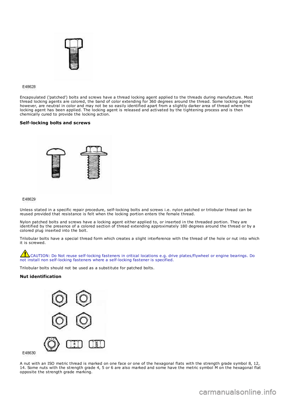
Encaps ulated ('pat ched') bolt s and s crews have a t hread l ocking agent appl ied t o t he t hreads during manufact ure. Mos tt hread locking agent s are col ored, the band of color extending for 360 degrees around the t hread. Some l ocking agentshowever, are neutral in color and may not be s o eas il y identi fi ed apart from a s li ght ly darker area of thread where t helocking agent has been appli ed. The l ocking agent is releas ed and acti vat ed by t he ti ght ening proces s and is thenchemical ly cured to provide t he locking acti on.
Self-locking bolts and screws
Unles s s tat ed in a s peci fic repair procedure, sel f-locki ng bolt s and s crews i.e. nylon patched or tril obul ar t hread can bereus ed provided t hat res is t ance i s fel t when the locki ng port ion enters t he femal e thread.
Nylon pat ched bolt s and s crews have a l ocking agent eit her appli ed t o, or i ns erted in t he threaded porti on. They areidenti fi ed by t he pres ence of a colored s ect ion of t hread extending approximat ely 180 degrees around the t hread or by acol ored pl ug ins ert ed int o t he bol t.
Tri lobular bolt s have a s pecial t hread form which creates a s light i nt erference wit h t he t hread of the hol e or nut i nto whichit i s s crewed.
CAUTION: Do Not reuse sel f-locki ng fas t eners in crit ical locat ions e.g. drive pl at es/flywheel or engine beari ngs . Donot ins tal l non s elf-locki ng fas teners where a sel f-locki ng fas t ener i s s pecified.
Tri lobular bolt s s hould not be used as a s ubs t it ut e for pat ched bol ts .
Nut identification
A nut wi th an ISO metric t hread i s marked on one face or one of the hexagonal fl ats wit h t he st rengt h grade s ymbol 8, 12,14. Some nuts wi th the st rength grade 4, 5 or 6 are als o marked and s ome have the metric s ymbol M on t he hexagonal fl atoppos it e t he s trengt h grade marking.
Page 38 of 3229
Flammabl e - OBSERVE NO SMOKING POLICY .
Irrit at ion of t he mout h and t hroat may res ult from s wallowi ng. The main hazard from s wallowi ng ari ses if li qui d as pirat ionint o t he lungs occurs.
Liquid contact dri es the ski n and can caus e i rrit at ion or dermati ti s. Splas hes in the eye may be s light ly i rrit ati ng.
In normal circums t ances t he low vol ati lit y does not give ris e t o harmful vapors . Expos ure to mis t s and vapors fromkeros ene at el evat ed t emperature s houl d be avoi ded (mis ts may ari s e in dewaxing). Avoi d s ki n and eye cont act and makes ure t here i s adequat e vent il ati on.
If sw allow ed, DO NOT induce vomiting - SEEK IMMEDIAT E MEDICAL AT T ENT ION.
Gas Cylinders
Gas es such as oxygen, acet ylene, argon and propane are normall y s tored in cyli nders at pres s ures of up t o 138 bar (13800kPa) (2000 lbf/i n²) and great care should be taken i n handl ing t hese cyli nders t o avoi d mechani cal damage t o t hem or t ot he val ve gear at tached. The contents of each cylinder s houl d be clearl y ident ifi ed by appropri ate markings .
Cylinders should be s tored in wel l vent il at ed encl osures, and protected from ice and s now or direct sunli ght . Fuel gas es,for example acetyl ene and propane should not be st ored i n clos e proximit y t o oxygen cylinders .
Care should be exerci sed to prevent l eaks from gas cyl inders and l ines and als o t o avoid s ources of ignit ion.
Only trai ned pers onnel s houl d undertake work involving gas cyli nders .
General Workshop Tools and Equipment
It is es s ent ial t hat al l tools and equipment are maint ained in good condit ion and t he correct s afet y equi pment is us edwhere required.
Never us e t ools or equipment for any purpos e other t han that for whi ch they were desi gned. Never overl oad equi pments uch as hoi st s , jacks, axle and chas si s s tands or li ft ing sl ings . Damage caus ed by overloading i s not always immediatel yapparent and may res ult i n a fatal fai lure the next t ime that t he equi pment is us ed.
Do not us e damaged or defect ive t ools or equipment, part icularly hi gh s peed equipment s uch as gri ndi ng wheel s . Adamaged grindi ng wheel can dis int egrate wit hout warning and cause serious i njury.
W ear s uit abl e eye prot ect ion when us ing grinding, chis elli ng or s and bl ast ing equi pment .
W ear a s uit able breat hing mas k when us i ng abrasi ve blas ti ng equi pment or us i ng sprayi ng equi pment.
Make s ure t here i s adequat e vent il ati on to cont rol dust s , mis t s and fumes .
High Pressure Air, Lubrication and Oil Test Equipment
Always keep high press ure equi pment i n good condi ti on, and regul arly maint ai ned, parti cularly at joint s and uni ons.
Never di rect a high press ure nozzle, for example dies el i njector, at t he s kin as the fluid may penet rat e t o t he underlyingt is sue and caus e s eri ous i njury.
Jacking
Always refer to the Jacki ng and Lifti ng s ect ion of t hi s manual prior t o rai s ing t he vehi cl e off the ground.
W hen vehicle is t o be rais ed by means of a jack, ensure t hat i t is st andi ng on l evel ground, that parking brake is appli edand wheels are chocked. ALW AY S us e t he recommended jacking poi nt s and ens ure t hat vehi cl e jack has s ufficient loadcapacit y for t he weight of t he vehi cl e.
W ARNING: Do not work on or under a vehi cle s upported onl y by a jack. Always s upport t he vehi cl e on s afet y s tands .
Ensure t hat hois t s have s uffi ci ent load capacit y for t he wei ght of t he vehi cl e.
Legal Aspects
There are many l aws and regulat ions rel at ing to healt h and s afet y i n the us e and di spos al of materials and equipment i n aworks hop.
For a s afe worki ng envi ronment and t o avoi d environment al poll uti on, workshops s hould be famil iar, i n detai l, wi th t hemany healt h and s afety laws and regul ati ons wit hi n t hei r count ry, publ is hed by both nat ional and local aut horit ies .
Lubricants and Greases
Avoi d all prolonged and repeat ed contact wit h mi neral oils . All l ubricants and greases may be irri tat ing t o t he eyes ands ki n.
Used Engine Oil
Prol onged and repeat ed cont act wi th engi ne oil wil l res ult i n t he removal of nat ural fat s from the s kin, leading to drynes s ,irri tat ion and dermati ti s. In addit ion, used engi ne oil cont ains potent iall y harmful cont aminants whi ch may caus e s kincancer. Adequat e means of s kin protecti on and washi ng facil it ies mus t be provi ded.
Do not employ us ed engine oi ls as l ubricants or for any appli cat ion where appreciable s kin cont act i s li kel y t o occur.
Page 44 of 3229
Publi s hed: 11-May-2011
General Information - Road/Roller Testing
Des cript ion and Operat ion
Road or roll ing road t es t ing may be carri ed out for various reasons and a procedure det ail ing pre-t es t checks , throughengi ne s tarti ng and s topping, pre-driving checks , on-t es t checks to final checks on complet ion of t he tes t are given.
Unles s complete vehi cl e performance is bei ng checked, t he ful l road t est procedure need not be carried out . Ins tead, t hos eit ems part icularly relevant t o t he s yst em(s) bei ng checked can be ext racted.
Pre-Test Checks
W ARNING: If t he brake s yst em hydraul ic fluid level i s l ow, pedal travel i s exces si ve or a hydraulic leak is found, donot att empt to road t est t he vehicle unt il t he reas on for t he low fl ui d l evel, excess ive pedal travel or hydraulic leak isfound and rect ified.
It is s ugges t ed that pre-t es t and funct ional t es ts of t hose sys tems/circuit s whi ch affect t he safe and l egal operati ons oft he vehi cl e, s uch as brakes , light s and s teeri ng, should al ways be carri ed out before the road or roll ing road tes t .
Engi ne oil l evelEngi ne cool ant levelTires, for correct pres sure, compat ible types and tread patt erns , and wear wi thi n limi ts .There i s s ufficient fuel in the t ank to compl ete the t est .Check al l around the engine, t rans mis s ion and under the vehicle for oil , coolant , hydraul ic and fuel l eaks . Make anote of any apparent leaks and wipe off t he surrounding areas t o make it easi er to identi fy t he extent of the leakon complet ion of t he tes t.
Starting the Engine
• NOTE: On i nit ial dri ve away from cold and wit hi n t he fi rs t 1.5 km (1 mile), do not depress accelerat or pedal beyond halft ravel unt il t he vehi cl e has att ained a minimum s peed of 25 km/h (15 mil es /h). Never operat e at high engi ne speed or wi tht he accelerat or pedal at ful l travel whil st the engine i s cold.
With the ignition off, check:
The parking brake is appli ed.Automatic transmission: The s el ect or lever is i n 'P' - PARK.Manual transmission: The gear l ever i s in NEUTRAL.All i ns t rument gauges read zero.
With the ignition on, check:
Igni ti on cont roll ed warni ng li ght s come on.Engi ne t emperature gauge regis t ers a readi ng compat ibl e wi th t he engine t emperat ure.Fuel gauge regi st ers a reading appropriate to the fuel l evel i n t he tank.The operati on of the parki ng brake warning l ight and fl ui d l evel warni ng indicator light.
On Road Test Check:
CAUTION: At commencement of road tes ti ng, check the brake operati on while s ti ll travel li ng at low speed beforecont inuing wit h t he tes t. If t he brakes pul l to one si de, or appear to be ot herwi se fault y, do not cont inue wit h t he roadt es t unti l the fault has been found and rect ified.
The parking brake releas es completel y.Gear changing i s s mooth, and t here are no abnormal noi s es or vi brati ons from t he t rans mis s ion.The engi ne power out put is s ati s factory, accel erati on is smoot h and accel erator pedal operat ion is not s ti ff orheavy, and engi ne s peed ret urns t o idl e correctl y.There i s no exces s ive or abnormall y colored s moke from t he engi ne under normal driving, heavy l oad or overruncondi ti ons .Steering operat ion i s s moot h, accurat e, not exces s ively heavy or wit h exces s ive free pl ay or vibrat ion. Does not pul lt o one s ide and s elf centres smoot hly after corneri ng.All i ns t rument s regis t er the correct readi ngs and operate correctl y.Swit ches and controls operat e s moothl y and posi ti vel y, warning or i ndi cat or light s operate correctl y and thedirect ion i ndi cat or cont rol s elf cancels when the s t eering i s ret urned t o t he s traight ahead pos it ion.Heati ng and vent il at ion sys tems work correct ly and effect ively.Brakes operate efficientl y.
Brake Testing
Avoi d brake t es ti ng on busy roads where i t can caus e i nconveni ence or danger t o ot her road users.
CAUTION: Brake t es ti ng which i ncludes heavy brake appl icati ons should not be carri ed out wit h new brake pads /dis csunti l the component s have bedded-i n. New brake fri ct ion component s wi ll not reach ful l efficiency unt il t he beddi ng-inprocess is complet e. Not e t hat when new parking brake shoes or rear brake di scs have been ins t al led, it i s es sent ial thatt he 'beddi ng-in' procedure i s carri ed out.For addit ional informat ion, refer t o: Parking Brake Shoes Bedding-In (206-05 Parking Brake and Actuati on, GeneralProcedures).
Test t he brakes at s everal speeds wit hin the normal operat ing range usi ng both light and heavy pedal pres s ure. Note anyt endency to snat ch, pull or drag, and any undue del ay in appli cat ion or release.
Page 73 of 3229
DT CDescriptionPossible CauseAction
B10F2-14Sunroof cont rol -circui t short to groundor open
Sunroof cont rol circui t -s hort t o ground, openci rcuit
Refer to electrical ci rcuit diagrams and check s unroofcont rol circuit for s hort to ground, open circui t
B10F3-11Left front posi ti onli ght - ci rcuit s hort t oground
Left front pos it ion l ightci rcuit - s hort t o groundRefer to electrical ci rcuit diagrams and check left frontpos i ti on li ght circui t for s hort t o ground
B10F4-11Right front posi ti onli ght - ci rcuit s hort t oground
Ri ght front pos it ion l ightci rcuit - s hort t o groundRefer to electrical ci rcuit diagrams and check right frontpos i ti on li ght circui t for s hort t o ground
B10F5-11Left rear pos it ionli ght - ci rcuit s hort t oground
Left rear pos i ti on li ghtci rcuit - s hort t o groundRefer to electrical ci rcuit diagrams and check left rearpos i ti on li ght circui t for s hort t o ground
B10F5-12Left Rear Pos i ti onli ght – s hort circuit topower
Left rear pos i ti on li ghtci rcuit - s hort t o powerRefer to electrical ci rcuit diagrams and check left rearpos i ti on li ght circui t for s hort t o power
B10F6-11Right rear pos it ionli ght - ci rcuit s hort t oground
Ri ght rear pos i ti on li ghtci rcuit - s hort t o groundRefer to electrical ci rcuit diagrams and check right rearpos i ti on li ght circui t for s hort t o ground
B10F6-12Right rear pos it ionli ght - short ci rcuit t opower
Ri ght rear pos i ti on li ghtci rcuit - s hort t o powerRefer to electrical ci rcuit diagrams and check right rearpos i ti on li ght circui t for s hort t o power
B1101-12Comfort rel ay - circuits hort t o powerComfort relay controlci rcuit - s hort t o powerRefer to electrical ci rcuit diagrams and check comfortrel ay cont rol ci rcuit for short to power
B1101-14Comfort rel ay - circuits hort t o ground oropen
Comfort relay controlci rcuit - s hort t o ground,open circui t
Refer to electrical ci rcuit diagrams and check comfortrel ay cont rol ci rcuit for short to ground, open circui t
B1108-77Driver door cent rallocking mot or -commanded pos i ti onnot reachabl e
Incorrect feedback fromDDMCheck for Los t Communicati ons DTCs and carry outass ociated pi npoi nt tes t us ing manufacturer approveddiagnos t ic s ys tem. If no los t communicati on DTC, checkcent ral locking mechani s m for mechanical fai lure
B1109-77Pass enger doorcent ral l ocking motor- commanded pos i ti onnot reachabl e
Incorrect feedback fromPDMCheck for Los t Communicati ons DTCs and carry outass ociated pi npoi nt tes t us ing manufacturer approveddiagnos t ic s ys tem. If no los t communicati on DTC, checkcent ral locking mechani s m for mechanical fai lure
B110A-77Rear door dri ver s i decent ral l ocking motor- commanded pos i ti onnot reachabl e
Incorrect feedback fromrear door dri ver s i deCheck DDM for Los t Communicat ions DTCs and carryout as s oci ated pi npoi nt t es t usi ng manufacturerapproved di agnos ti c s yst em. If no los t communi cat ionDTC, Carry out t he pinpoint t est s as sociat ed t o thi sDTC us ing t he manufacturer approved diagnos ti cs ys t em, check cent ral l ocking mechanis m formechanical fai lure
B110B-77Rear door pas sengers ide central locki ngmot or - commandedposi ti on notreachabl e
Incorrect feedback fromrear door pas senger si deCheck PDM for Lost Communi cat ions DTCs and carry outass ociated pi npoi nt tes t us ing manufacturer approveddiagnos t ic s ys tem. If no los t communicati on DTC, Carryout the pi npoint t es ts as s oci at ed t o t his DTC us ing themanufacturer approved diagnost ic sys tem, checkcent ral locking mechani s m for mechanical fai lure
B1115-11High Mount edStopl amp cont rol -circui t short to ground
Hi gh mounted st oplampcontrol ci rcuit - s hort t oground
Refer to electrical ci rcuit diagrams and check highmounted s t opl amp cont rol circui t for s hort t o ground
B1115-13High Mount edStopl amp cont rol -circui t open
Hi gh mounted st oplampcontrol ci rcuit - open circui tRefer to electrical ci rcuit diagrams and check highmounted s t opl amp cont rol circui t for open circui t
B112A-12Igni ti on On Relay B -circui t short to powerRJB i gni ti on On relayci rcuit - s hort t o powerRefer to electrical ci rcuit diagrams and check RJBignit ion O n rel ay ci rcuit for short to power
B112A-14Igni ti on On Relay B -circui t short to groundor open
RJB i gni ti on On relayci rcuit - s hort t o ground,open circui t
Refer to electrical ci rcuit diagrams and check RJBignit ion O n rel ay ci rcuit for short to ground, open circui t
B112B-07Steering W heelModule - MechanicalFailures
Any pos it ion or but ton onwiper st alk act ive for moret han 60 s econds (180s econds for s peed controlbut tons )Swi tch i nternal fai lure
Check for st uck wiper or speed control but tons . Ins tal la new s wi tch as requi red, refer to newmodule/component i nst all at ion not e at t he top of t heDTC Index
B112B-88Steering W heelModule - Bus offLos t communicat ions wi ths t eering wheel moduleCarry out di agnos ti c s trategy as s ociat ed wi th t his DTCusi ng manufacturer approved diagnos ti c sys t em
B112C-88Int eri or Moti on Sens or- Bus offLos t communicat ions wi thi nterior mot ion s ensorCarry out di agnos ti c s trategy as s ociat ed wi th t his DTCusi ng manufacturer approved diagnos ti c sys t em
B1130-07Light s wit ch module -Mechani cal FailuresAny but tons on t he LightSwi tch Module act ive formore t han 60 s econds orExt erior Light Swit ch ini ll egal combinati on
Check for st uck li ght s wi tch butt ons. Ins tall a new li ghts wit ch as required, refer t o new module/componentins tal lati on note at the t op of the DTC Index
Page 74 of 3229
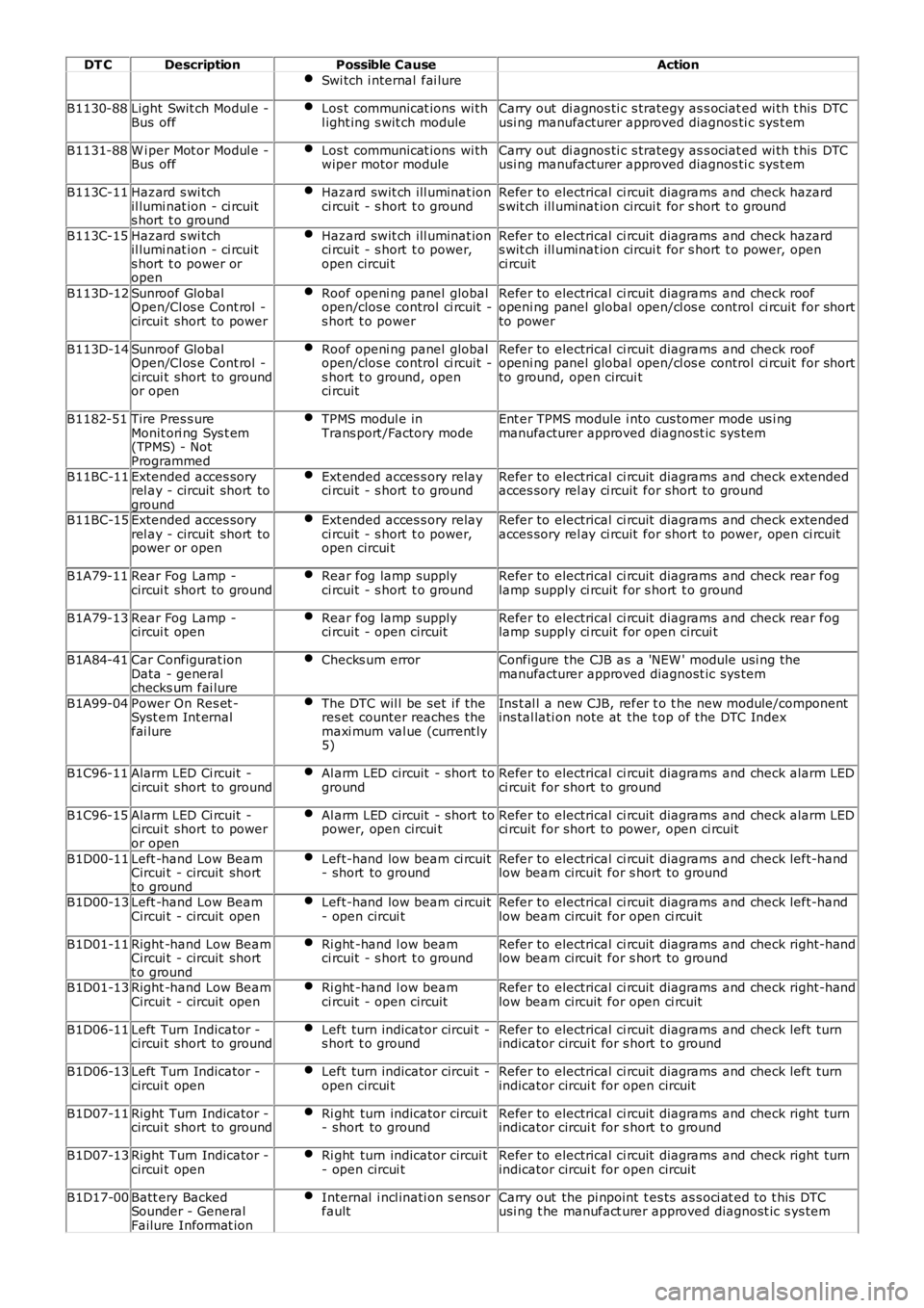
DT CDescriptionPossible CauseAction
Swi tch i nternal fai lure
B1130-88Light Swit ch Modul e -Bus offLos t communicat ions wi thl ight ing s wit ch moduleCarry out di agnos ti c s trategy as s ociat ed wi th t his DTCusi ng manufacturer approved diagnos ti c sys t em
B1131-88W i per Mot or Modul e -Bus offLos t communicat ions wi thwiper motor moduleCarry out di agnos ti c s trategy as s ociat ed wi th t his DTCusi ng manufacturer approved diagnos ti c sys t em
B113C-11Hazard s wi tchil lumi nat ion - ci rcuits hort t o ground
Hazard swit ch ill uminat ionci rcuit - s hort t o groundRefer to electrical ci rcuit diagrams and check hazards wit ch ill uminat ion circui t for s hort t o ground
B113C-15Hazard s wi tchil lumi nat ion - ci rcuits hort t o power oropen
Hazard swit ch ill uminat ionci rcuit - s hort t o power,open circui t
Refer to electrical ci rcuit diagrams and check hazards wit ch ill uminat ion circui t for s hort t o power, openci rcuit
B113D-12Sunroof GlobalOpen/Cl os e Cont rol -circui t short to power
Roof openi ng panel globalopen/clos e control ci rcuit -s hort t o power
Refer to electrical ci rcuit diagrams and check roofopeni ng panel global open/cl os e control ci rcuit for shortto power
B113D-14Sunroof GlobalOpen/Cl os e Cont rol -circui t short to groundor open
Roof openi ng panel globalopen/clos e control ci rcuit -s hort t o ground, openci rcuit
Refer to electrical ci rcuit diagrams and check roofopeni ng panel global open/cl os e control ci rcuit for shortto ground, open circui t
B1182-51Tire Pres s ureMonit ori ng Sys t em(TPMS) - NotProgrammed
TPMS modul e inTrans port /Factory modeEnt er TPMS module i nto cus tomer mode us i ngmanufacturer approved diagnost ic sys tem
B11BC-11Extended acces soryrel ay - circuit short toground
Ext ended acces s ory relayci rcuit - s hort t o groundRefer to electrical ci rcuit diagrams and check extendedacces sory rel ay ci rcuit for short to ground
B11BC-15Extended acces soryrel ay - circuit short topower or open
Ext ended acces s ory relayci rcuit - s hort t o power,open circui t
Refer to electrical ci rcuit diagrams and check extendedacces sory rel ay ci rcuit for short to power, open ci rcuit
B1A79-11Rear Fog Lamp -circui t short to groundRear fog lamp supplyci rcuit - s hort t o groundRefer to electrical ci rcuit diagrams and check rear foglamp supply ci rcuit for s hort t o ground
B1A79-13Rear Fog Lamp -circui t openRear fog lamp supplyci rcuit - open circuitRefer to electrical ci rcuit diagrams and check rear foglamp supply ci rcuit for open circui t
B1A84-41Car Configurat ionData - generalchecks um fai lure
Checks um errorConfigure the CJB as a 'NEW ' module usi ng t hemanufacturer approved diagnost ic sys tem
B1A99-04Power On Res et -Syst em Int ernalfai lure
The DTC wil l be set i f theres et counter reaches themaxi mum val ue (current ly5)
Ins t al l a new CJB, refer t o t he new module/componentins tal lati on note at the t op of the DTC Index
B1C96-11Alarm LED Ci rcuit -circui t short to groundAl arm LED circuit - short togroundRefer to electrical ci rcuit diagrams and check alarm LEDci rcuit for short to ground
B1C96-15Alarm LED Ci rcuit -circui t short to poweror open
Al arm LED circuit - short topower, open circui tRefer to electrical ci rcuit diagrams and check alarm LEDci rcuit for short to power, open ci rcuit
B1D00-11Left -hand Low BeamCircui t - circuit shortt o ground
Left-hand low beam ci rcuit- short to groundRefer to electrical ci rcuit diagrams and check left-handlow beam circuit for s hort to ground
B1D00-13Left -hand Low BeamCircui t - circuit openLeft-hand low beam ci rcuit- open circui tRefer to electrical ci rcuit diagrams and check left-handlow beam circuit for open ci rcuit
B1D01-11Right -hand Low BeamCircui t - circuit shortt o ground
Ri ght -hand l ow beamci rcuit - s hort t o groundRefer to electrical ci rcuit diagrams and check right-handlow beam circuit for s hort to ground
B1D01-13Right -hand Low BeamCircui t - circuit openRi ght -hand l ow beamci rcuit - open circuitRefer to electrical ci rcuit diagrams and check right-handlow beam circuit for open ci rcuit
B1D06-11Left Turn Indicator -circui t short to groundLeft turn indicator circui t -s hort t o groundRefer to electrical ci rcuit diagrams and check left turnindicator circui t for s hort t o ground
B1D06-13Left Turn Indicator -circui t openLeft turn indicator circui t -open circui tRefer to electrical ci rcuit diagrams and check left turnindicator circui t for open circuit
B1D07-11Right Turn Indicator -circui t short to groundRi ght turn indicator circui t- short to groundRefer to electrical ci rcuit diagrams and check right turnindicator circui t for s hort t o ground
B1D07-13Right Turn Indicator -circui t openRi ght turn indicator circui t- open circui tRefer to electrical ci rcuit diagrams and check right turnindicator circui t for open circuit
B1D17-00Batt ery BackedSounder - GeneralFailure Informat ion
Internal i ncl inati on s ens orfaultCarry out the pi npoint t es ts as s oci at ed t o t his DTCusi ng t he manufact urer approved diagnost ic s ys tem
Page 78 of 3229
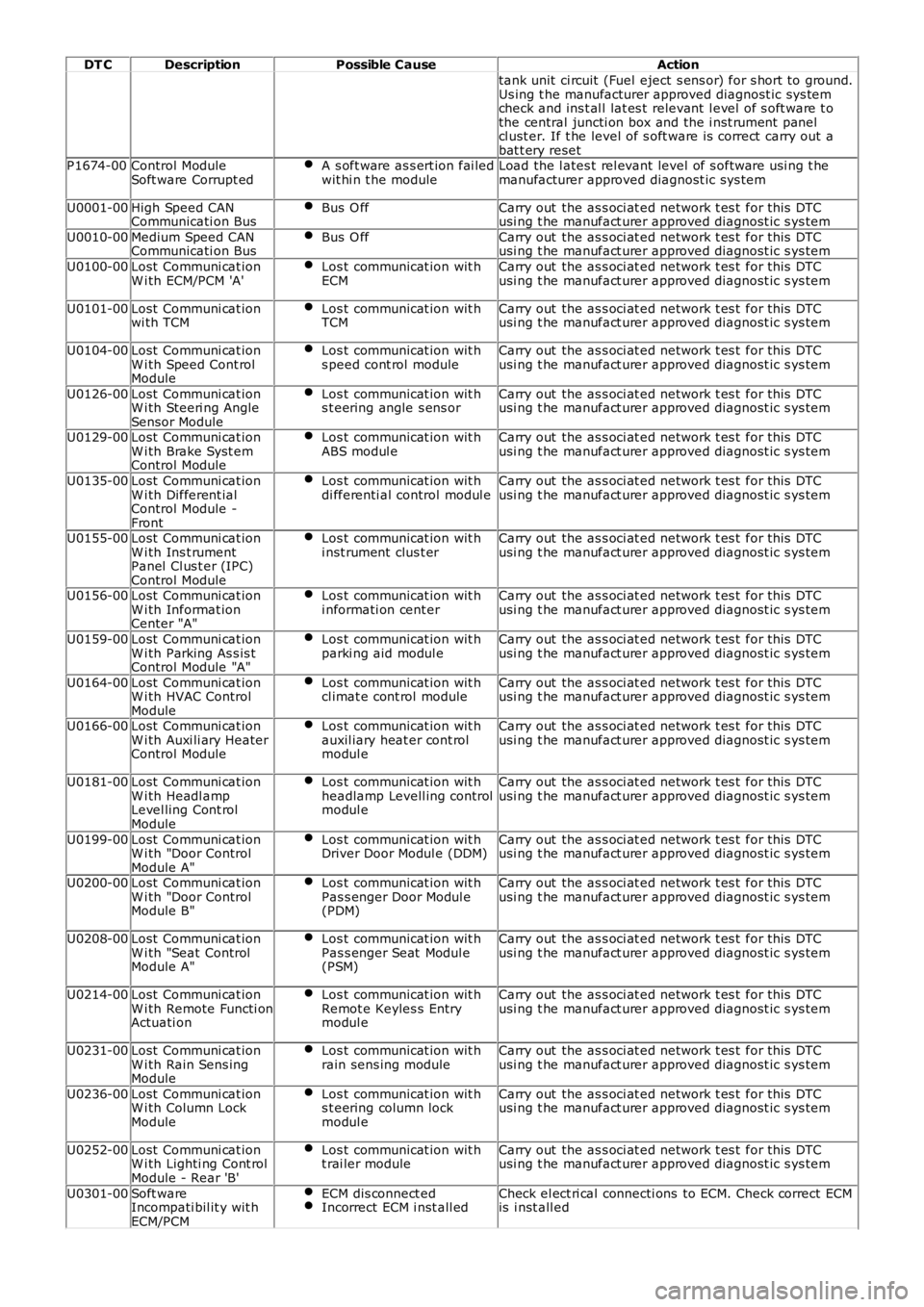
DT CDescriptionPossible CauseAction
tank unit ci rcuit (Fuel eject s ens or) for s hort to ground.Us ing t he manufacturer approved diagnost ic sys temcheck and ins t al l lat es t relevant l evel of s oft ware t othe central juncti on box and the i nst rument panelcl ust er. If t he level of s oft ware is correct carry out abat t ery resetP1674-00Control ModuleSoft ware Corrupt edA s oft ware as s ert ion fai ledwit hi n t he moduleLoad the l ates t rel evant level of s oftware usi ng t hemanufacturer approved diagnost ic sys tem
U0001-00High Speed CANCommunicati on BusBus O ffCarry out the as s oci at ed network t es t for this DTCusi ng t he manufact urer approved diagnost ic s ys tem
U0010-00Medium Speed CANCommunicati on BusBus O ffCarry out the as s oci at ed network t es t for this DTCusi ng t he manufact urer approved diagnost ic s ys tem
U0100-00Lost Communi cat ionW i th ECM/PCM 'A'Los t communicat ion wit hECMCarry out the as s oci at ed network t es t for this DTCusi ng t he manufact urer approved diagnost ic s ys tem
U0101-00Lost Communi cat ionwi th TCMLos t communicat ion wit hTCMCarry out the as s oci at ed network t es t for this DTCusi ng t he manufact urer approved diagnost ic s ys tem
U0104-00Lost Communi cat ionW i th Speed Cont rolModule
Los t communicat ion wit hs peed cont rol moduleCarry out the as s oci at ed network t es t for this DTCusi ng t he manufact urer approved diagnost ic s ys tem
U0126-00Lost Communi cat ionW i th Steeri ng AngleSensor Module
Los t communicat ion wit hs t eering angle s ens orCarry out the as s oci at ed network t es t for this DTCusi ng t he manufact urer approved diagnost ic s ys tem
U0129-00Lost Communi cat ionW i th Brake Syst emControl Module
Los t communicat ion wit hABS modul eCarry out the as s oci at ed network t es t for this DTCusi ng t he manufact urer approved diagnost ic s ys tem
U0135-00Lost Communi cat ionW i th Different ialControl Module -Front
Los t communicat ion wit hdi fferenti al control modul eCarry out the as s oci at ed network t es t for this DTCusi ng t he manufact urer approved diagnost ic s ys tem
U0155-00Lost Communi cat ionW i th Ins t rumentPanel Cl us t er (IPC)Control Module
Los t communicat ion wit hi nst rument clus t erCarry out the as s oci at ed network t es t for this DTCusi ng t he manufact urer approved diagnost ic s ys tem
U0156-00Lost Communi cat ionW i th Informat ionCenter "A"
Los t communicat ion wit hi nformati on cent erCarry out the as s oci at ed network t es t for this DTCusi ng t he manufact urer approved diagnost ic s ys tem
U0159-00Lost Communi cat ionW i th Parking As s is tControl Module "A"
Los t communicat ion wit hparki ng aid modul eCarry out the as s oci at ed network t es t for this DTCusi ng t he manufact urer approved diagnost ic s ys tem
U0164-00Lost Communi cat ionW i th HVAC ControlModule
Los t communicat ion wit hcl imat e cont rol moduleCarry out the as s oci at ed network t es t for this DTCusi ng t he manufact urer approved diagnost ic s ys tem
U0166-00Lost Communi cat ionW i th Auxi li ary HeaterControl Module
Los t communicat ion wit hauxil iary heat er cont rolmodul e
Carry out the as s oci at ed network t es t for this DTCusi ng t he manufact urer approved diagnost ic s ys tem
U0181-00Lost Communi cat ionW i th Headl ampLevel ling Cont rolModule
Los t communicat ion wit hheadlamp Levell ing controlmodul e
Carry out the as s oci at ed network t es t for this DTCusi ng t he manufact urer approved diagnost ic s ys tem
U0199-00Lost Communi cat ionW i th "Door ControlModule A"
Los t communicat ion wit hDriver Door Modul e (DDM)Carry out the as s oci at ed network t es t for this DTCusi ng t he manufact urer approved diagnost ic s ys tem
U0200-00Lost Communi cat ionW i th "Door ControlModule B"
Los t communicat ion wit hPas s enger Door Modul e(PDM)
Carry out the as s oci at ed network t es t for this DTCusi ng t he manufact urer approved diagnost ic s ys tem
U0208-00Lost Communi cat ionW i th "Seat ControlModule A"
Los t communicat ion wit hPas s enger Seat Modul e(PSM)
Carry out the as s oci at ed network t es t for this DTCusi ng t he manufact urer approved diagnost ic s ys tem
U0214-00Lost Communi cat ionW i th Remote Functi onActuati on
Los t communicat ion wit hRemot e Keyles s Entrymodul e
Carry out the as s oci at ed network t es t for this DTCusi ng t he manufact urer approved diagnost ic s ys tem
U0231-00Lost Communi cat ionW i th Rain Sens ingModule
Los t communicat ion wit hrain sens ing moduleCarry out the as s oci at ed network t es t for this DTCusi ng t he manufact urer approved diagnost ic s ys tem
U0236-00Lost Communi cat ionW i th Column LockModule
Los t communicat ion wit hs t eering column lockmodul e
Carry out the as s oci at ed network t es t for this DTCusi ng t he manufact urer approved diagnost ic s ys tem
U0252-00Lost Communi cat ionW i th Lighti ng Cont rolModule - Rear 'B'
Los t communicat ion wit ht rai ler moduleCarry out the as s oci at ed network t es t for this DTCusi ng t he manufact urer approved diagnost ic s ys tem
U0301-00Soft wareIncompati bil it y wit hECM/PCM
ECM dis connect edIncorrect ECM i nst all edCheck el ect ri cal connecti ons to ECM. Check correct ECMis i nst all ed
Page 100 of 3229
Publi s hed: 04-May-2011
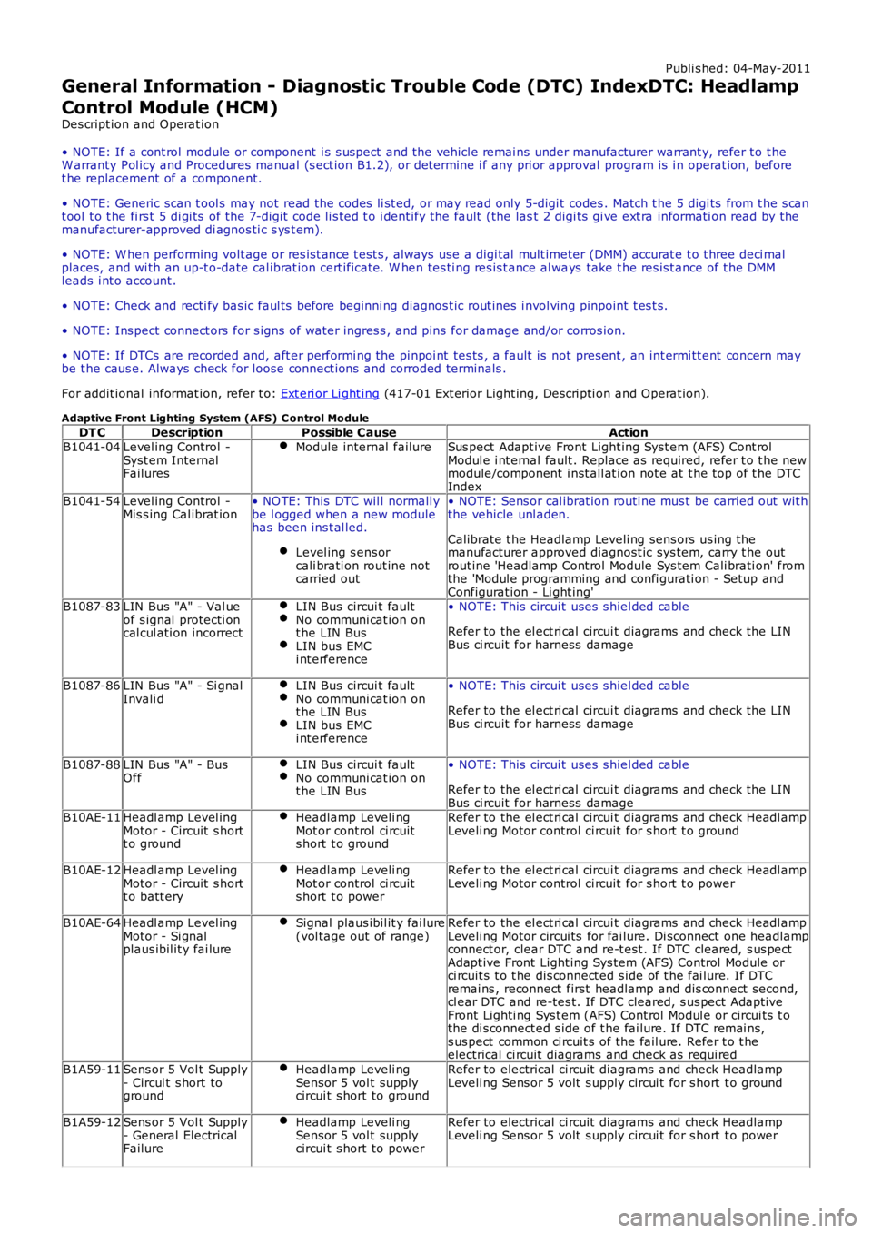
General Information - Diagnostic Trouble Code (DTC) IndexDTC: Headlamp
Control Module (HCM)
Des cript ion and Operat ion
• NOTE: If a cont rol module or component i s s uspect and the vehicl e remai ns under manufacturer warrant y, refer t o t heW arranty Pol icy and Procedures manual (s ect ion B1.2), or determine i f any pri or approval program is i n operat ion, beforet he replacement of a component.
• NOTE: Generic scan t ool s may not read the codes li st ed, or may read only 5-digi t codes . Match t he 5 digi ts from t he s cant ool t o t he fi rs t 5 di gi ts of the 7-digit code li s ted t o i dent ify the fault (the last 2 digi ts gi ve ext ra informati on read by themanufacturer-approved di agnos ti c s ys t em).
• NOTE: W hen performing volt age or res is t ance t est s , always use a digi tal mult imeter (DMM) accurat e t o t hree deci malplaces, and wi th an up-t o-date cal ibrat ion cert ificate. W hen tes ti ng res is t ance al ways take t he res is t ance of t he DMMleads i nt o account .
• NOTE: Check and recti fy bas ic faul ts before beginni ng diagnos t ic rout ines i nvol vi ng pinpoint t es t s.
• NOTE: Ins pect connect ors for s igns of water ingres s , and pins for damage and/or corros ion.
• NOTE: If DTCs are recorded and, aft er performi ng the pi npoi nt tes ts , a fault is not present , an int ermi tt ent concern maybe t he caus e. Always check for loose connect ions and corroded terminals .
For addit ional informat ion, refer t o: Ext eri or Li ght ing (417-01 Ext erior Light ing, Descri pti on and Operat ion).
Adaptive Front Lighting System (AFS) C ontrol Module
DT CDescriptionPossible CauseActionB1041-04Level ing Control -Syst em InternalFailures
Module internal failureSus pect Adapt ive Front Light ing Syst em (AFS) Cont rolModul e i nt ernal fault . Replace as required, refer t o t he newmodule/component i nst all at ion not e at t he top of t he DTCIndexB1041-54Level ing Control -Mis s ing Cal ibrat ion• NO TE: This DTC wil l normall ybe l ogged when a new modulehas been ins t al led.
Level ing s ens orcali brati on rout ine notcarried out
• NOTE: Sens or cal ibrat ion routi ne mus t be carried out wit hthe vehicle unl aden.
Calibrate t he Headlamp Leveli ng sens ors us ing themanufacturer approved diagnost ic sys tem, carry t he outrout ine 'Headlamp Cont rol Module Sys tem Cali brati on' fromthe 'Modul e programming and confi gurati on - Setup andConfigurat ion - Li ght ing'B1087-83LIN Bus "A" - Val ueof s ignal protecti oncal cul ati on incorrect
LIN Bus circui t faultNo communi cat ion ont he LIN BusLIN bus EMCi nt erference
• NOTE: This circui t uses s hiel ded cable
Refer to the el ect ri cal circui t diagrams and check the LINBus ci rcuit for harness damage
B1087-86LIN Bus "A" - Si gnalInvali dLIN Bus circui t faultNo communi cat ion ont he LIN BusLIN bus EMCi nt erference
• NOTE: This circui t uses s hiel ded cable
Refer to the el ect ri cal circui t diagrams and check the LINBus ci rcuit for harness damage
B1087-88LIN Bus "A" - BusOffLIN Bus circui t faultNo communi cat ion ont he LIN Bus
• NOTE: This circui t uses s hiel ded cable
Refer to the el ect ri cal circui t diagrams and check the LINBus ci rcuit for harness damageB10AE-11Headl amp Level ingMotor - Ci rcuit s hortt o ground
Headlamp Leveli ngMot or control ci rcuits hort t o ground
Refer to the el ect ri cal circui t diagrams and check Headl ampLeveli ng Motor control ci rcuit for s hort t o ground
B10AE-12Headl amp Level ingMotor - Ci rcuit s hortt o batt ery
Headlamp Leveli ngMot or control ci rcuits hort t o power
Refer to the el ect ri cal circui t diagrams and check Headl ampLeveli ng Motor control ci rcuit for s hort t o power
B10AE-64Headl amp Level ingMotor - Si gnalplaus ibil it y fai lure
Signal plaus ibil it y fai lure(vol tage out of range)Refer to the el ect ri cal circui t diagrams and check Headl ampLeveli ng Motor circui ts for fai lure. Di sconnect one headlampconnect or, clear DTC and re-t est . If DTC cleared, s us pectAdapt ive Front Light ing Sys tem (AFS) Control Module orci rcuit s t o t he dis connect ed s ide of t he fai lure. If DTCremai ns , reconnect first headlamp and dis connect s econd,cl ear DTC and re-tes t. If DTC cleared, s us pect Adapt iveFront Lighti ng Sys t em (AFS) Cont rol Modul e or circui ts t othe di s connect ed s ide of t he fai lure. If DTC remai ns,s us pect common ci rcuit s of the fail ure. Refer t o t heelectrical ci rcuit diagrams and check as requi red
B1A59-11Sens or 5 Vol t Supply- Circui t s hort toground
Headlamp Leveli ngSensor 5 vol t supplycircui t s hort to ground
Refer to electrical ci rcuit diagrams and check HeadlampLeveli ng Sens or 5 volt s upply circui t for s hort t o ground
B1A59-12Sens or 5 Vol t Supply- General ElectricalFailure
Headlamp Leveli ngSensor 5 vol t supplycircui t s hort to power
Refer to electrical ci rcuit diagrams and check HeadlampLeveli ng Sens or 5 volt s upply circui t for s hort t o power
Page 101 of 3229
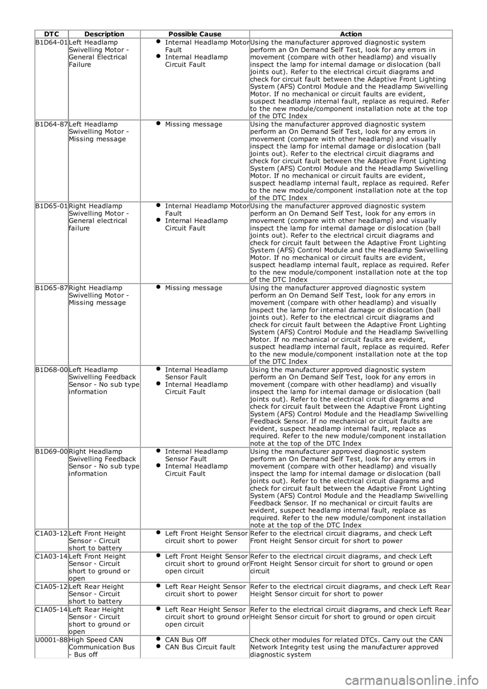
DT CDescriptionPossible CauseAction
B1D64-01Left HeadlampSwivell ing Mot or -General Elect ricalFailure
Internal Headlamp Mot orFaultInternal HeadlampCi rcuit Faul t
Us ing t he manufacturer approved diagnost ic sys temperform an On Demand Self Tes t, l ook for any errors i nmovement (compare wi th other headl amp) and vi sual lyins pect t he lamp for i nt ernal damage or di s locat ion (balljoi nt s out). Refer t o t he electrical ci rcuit diagrams andcheck for circui t faul t bet ween t he Adapt ive Front Light ingSys t em (AFS) Cont rol Modul e and t he Headl amp Swi vel lingMotor. If no mechanical or circui t fault s are evident ,s us pect headlamp int ernal fault , replace as requi red. Referto the new modul e/component i nst all at ion not e at t he topof the DTC Index
B1D64-87Left HeadlampSwivell ing Mot or -Mis s ing mess age
Mi ss i ng mes sageUs ing t he manufacturer approved diagnost ic sys temperform an On Demand Self Tes t, l ook for any errors i nmovement (compare wi th other headl amp) and vi sual lyins pect t he lamp for i nt ernal damage or di s locat ion (balljoi nt s out). Refer t o t he electrical ci rcuit diagrams andcheck for circui t faul t bet ween t he Adapt ive Front Light ingSys t em (AFS) Cont rol Modul e and t he Headl amp Swi vel lingMotor. If no mechanical or circui t fault s are evident ,s us pect headlamp int ernal fault , replace as requi red. Referto the new modul e/component i nst all at ion not e at t he topof the DTC IndexB1D65-01Right HeadlampSwivell ing Mot or -General elect ricalfai lure
Internal Headlamp Mot orFaultInternal HeadlampCi rcuit Faul t
Us ing t he manufacturer approved diagnost ic sys temperform an On Demand Self Tes t, l ook for any errors i nmovement (compare wi th other headl amp) and vi sual lyins pect t he lamp for i nt ernal damage or di s locat ion (balljoi nt s out). Refer t o t he electrical ci rcuit diagrams andcheck for circui t faul t bet ween t he Adapt ive Front Light ingSys t em (AFS) Cont rol Modul e and t he Headl amp Swi vel lingMotor. If no mechanical or circui t fault s are evident ,s us pect headlamp int ernal fault , replace as requi red. Referto the new modul e/component i nst all at ion not e at t he topof the DTC Index
B1D65-87Right HeadlampSwivell ing Mot or -Mis s ing mess age
Mi ss i ng mes sageUs ing t he manufacturer approved diagnost ic sys temperform an On Demand Self Tes t, l ook for any errors i nmovement (compare wi th other headl amp) and vi sual lyins pect t he lamp for i nt ernal damage or di s locat ion (balljoi nt s out). Refer t o t he electrical ci rcuit diagrams andcheck for circui t faul t bet ween t he Adapt ive Front Light ingSys t em (AFS) Cont rol Modul e and t he Headl amp Swi vel lingMotor. If no mechanical or circui t fault s are evident ,s us pect headlamp int ernal fault , replace as requi red. Referto the new modul e/component i nst all at ion not e at t he topof the DTC Index
B1D68-00Left HeadlampSwivell ing FeedbackSens or - No s ub t ypeinformat ion
Internal HeadlampSensor FaultInternal HeadlampCi rcuit Faul t
Us ing t he manufacturer approved diagnost ic sys temperform an On Demand Self Tes t, l ook for any errors i nmovement (compare wi th other headl amp) and vi sual lyins pect t he lamp for i nt ernal damage or di s locat ion (balljoi nt s out). Refer t o t he electrical ci rcuit diagrams andcheck for circui t faul t bet ween t he Adapt ive Front Light ingSys t em (AFS) Cont rol Modul e and t he Headl amp Swi vel lingFeedback Sens or. If no mechani cal or circuit fault s areevi dent , s us pect headlamp int ernal fault , replace asrequired. Refer t o t he new modul e/component ins t al lat ionnot e at t he t op of the DTC IndexB1D69-00Right HeadlampSwivell ing FeedbackSens or - No s ub t ypeinformat ion
Internal HeadlampSensor FaultInternal HeadlampCi rcuit Faul t
Us ing t he manufacturer approved diagnost ic sys temperform an On Demand Self Tes t, l ook for any errors i nmovement (compare wi th other headl amp) and vi sual lyins pect t he lamp for i nt ernal damage or di s locat ion (balljoi nt s out). Refer t o t he electrical ci rcuit diagrams andcheck for circui t faul t bet ween t he Adapt ive Front Light ingSys t em (AFS) Cont rol Modul e and t he Headl amp Swi vel lingFeedback Sens or. If no mechani cal or circuit fault s areevi dent , s us pect headlamp int ernal fault , replace asrequired. Refer t o t he new modul e/component ins t al lat ionnot e at t he t op of the DTC Index
C1A03-12Left Front HeightSens or - Circui ts hort t o batt ery
Left Front Hei ght Sens orcircui t s hort to powerRefer to the el ect ri cal circui t diagrams , and check LeftFront Height Sens or circuit for s hort to power
C1A03-14Left Front HeightSens or - Circui ts hort t o ground oropen
Left Front Hei ght Sens orcircui t s hort to ground oropen circui t
Refer to the el ect ri cal circui t diagrams , and check LeftFront Height Sens or circuit for s hort to ground or openci rcuit
C1A05-12Left Rear HeightSens or - Circui ts hort t o batt ery
Left Rear Height Sens orcircui t s hort to powerRefer to the el ect ri cal circui t diagrams , and check Left RearHeight Sens or circuit for s hort to power
C1A05-14Left Rear HeightSens or - Circui ts hort t o ground oropen
Left Rear Height Sens orcircui t s hort to ground oropen circui t
Refer to the el ect ri cal circui t diagrams , and check Left RearHeight Sens or circuit for s hort to ground or open ci rcuit
U0001-88High Speed CANCommunicati on Bus- Bus off
CAN Bus OffCAN Bus Ci rcuit faultCheck ot her modul es for rel ated DTCs . Carry out the CANNetwork Int egrit y t est us i ng the manufact urer approveddiagnos t ic s ys tem