2006 LAND ROVER FRELANDER 2 light
[x] Cancel search: lightPage 1109 of 3229
Fuel fired heat er
The FFBH (fuel fired boost er heat er) and St op/Start s ys t em wi ll not operate si mult aneous ly, due to low ambientt emperatures bei ng a fact or in t he funct ion of both sys tems .
Hood Latch Ajar-Switch
W ARNING: To avoi d injury when performing repai r work on t he vehicle al ways di s abl e the Stop/St art s ys tem bypres s ing t he ‘ECO’ butt on, ens ure that ‘ECO STOP/START OFF’ is di s pl ayed in t he mes sage Cent er and the ECO tel l-taleli ght in t he s wit ch is ext inguis hed.
The hood lat ch ajar-s wit ch hardwired to the CJB, has two functi ons :
Acts as a s top i nhi bit or, all owing t he engi ne t o remai n running if t he hood latch i s rel eased.Deact ivates the St op/Start s ys t em i f an engi ne s top i s t aki ng place, t his res ul ts in an engine st all ed condit ion. Theengi ne can be res t art ed usi ng t he ignit ion but ton. Stal l recovery wil l not funct ion i n t hi s condi ti on; refer t o t he StallRecovery secti on.
Aft er the hood i s clos ed reacti vat ion of t he Stop/Start sys tem is achieved by manuall y s tarti ng the engine.
System Fault
The Stop/St art s ys tem is aut omati cal ly acti vat ed each ti me an ignit ion cycl e occurs; t he dri ver will be i nformed t he sys t emis operat ing by the t ell -t ale l ight in the Eco s wi tch i lluminati ng. If the tell -t ale light does not il luminat e t hi s wi ll indicat et hat t here i s eit her a s ys t em faul t or the sys tem is not avail abl e. Onl y when t he dri ver at tempt s t o act ivat e t he sys t em bypres s ing t he ‘Eco’ but ton will t hey be informed of a fault by ‘ECO STOP/START FAULT’ being di spl ayed i n t he mes sageCenter.
Owi ng to the St op/Start s ys t em’s complexit y due t o many ot her vehicle modul es and communicat ion net works i nvol ved i nit s funct ion. It i s recommended t hat al l ot her sys tem faul ts be init ial ly diagnos ed and eliminated when inves t igati ngStop/St art fault s as t hes e could affect the operat ion of t he St op/Start sys tem.
Syst em DTC (di agnos ti c troubl e code)can be diagnos ed us ing Land Rover approved di agnos ti c equi pment.
STOP INHIBITORS, START INITIATORS AND START INHIBITORS
A number of s el ect able feat ures or vehicle si tuat ions can infl uence t he operat ion of t he Stop/St art s yst em’s operati on.Thes e can, depending on the parti cular circumst ances :
prevent the engine s hutt ing down (s t op inhibi tor),ini ti at e an aut onomous res tart (s tart ini ti at or),prevent an engi ne res t art (st art i nhi bit or).
Stop Inhibitors
Under normal ci rcums tances the St op/St art s ys t em wi ll automat icall y s hut down t he engi ne if:
t he vehi cl e is st ati onary,t he trans mi s si on is in neutral,t he cl utch pedal i s ful ly releas ed.
The fol lowing condit ions wi ll inhibi t the engine from s hutt ing down:
Dri ver effected st op inhi bi tor
The fol lowing driver effect ed condi ti ons will i nhi bit t he engi ne from shut ti ng down:
Dri ver s wi tches off t he Stop/St art s ys temTrans mis s ion not i n neut ral((no te that the d rive r re sting their ha nd o n the g ea r le ve r ca n move the tra ns mis sion o ut o f the ne utra l w ind o w w itho ut e nga g ing a ge a r))
Clut ch pedal not full y rel easedAccelerator pedal depres s edHood is openDri ver’s door is openDri ver’s safet y belt i s dis engagedHDC (hil l decent cont rol) i s acti veTR (terrain res pons e) mode i s act iveCli mate cont rol s ys t em us ed above cal ibrat ed thresholdW i nds hiel d demis t i s operati ngTrai ler electrical connect ion det ect ed
Vehicle s ys tem effect ed s top i nhi bit or
The fol lowing vehicl e s ys t em condi ti ons wil l inhibit t he engine from s hut ti ng down:
Dri ver s wi tches off t he Stop/St art s ys temBrake s ervo vacuum below thres holdBatt ery cold cranki ng capabil it y below t hres holdBatt ery s t ate of charge i s lowCatal yt ic converter out si de eit her pre or post cali brati on rangeDPF (di esel part iculat e filt er) i s regenerat ingEngi ne cool ant temperat ure bel ow t hreshol dEngi ne oil t emperature below thres hold
Page 1369 of 3229
Publi s hed: 11-May-2011
Automatic Transmission/Transaxle External Controls - External Controls
Des cript ion and Operat ion
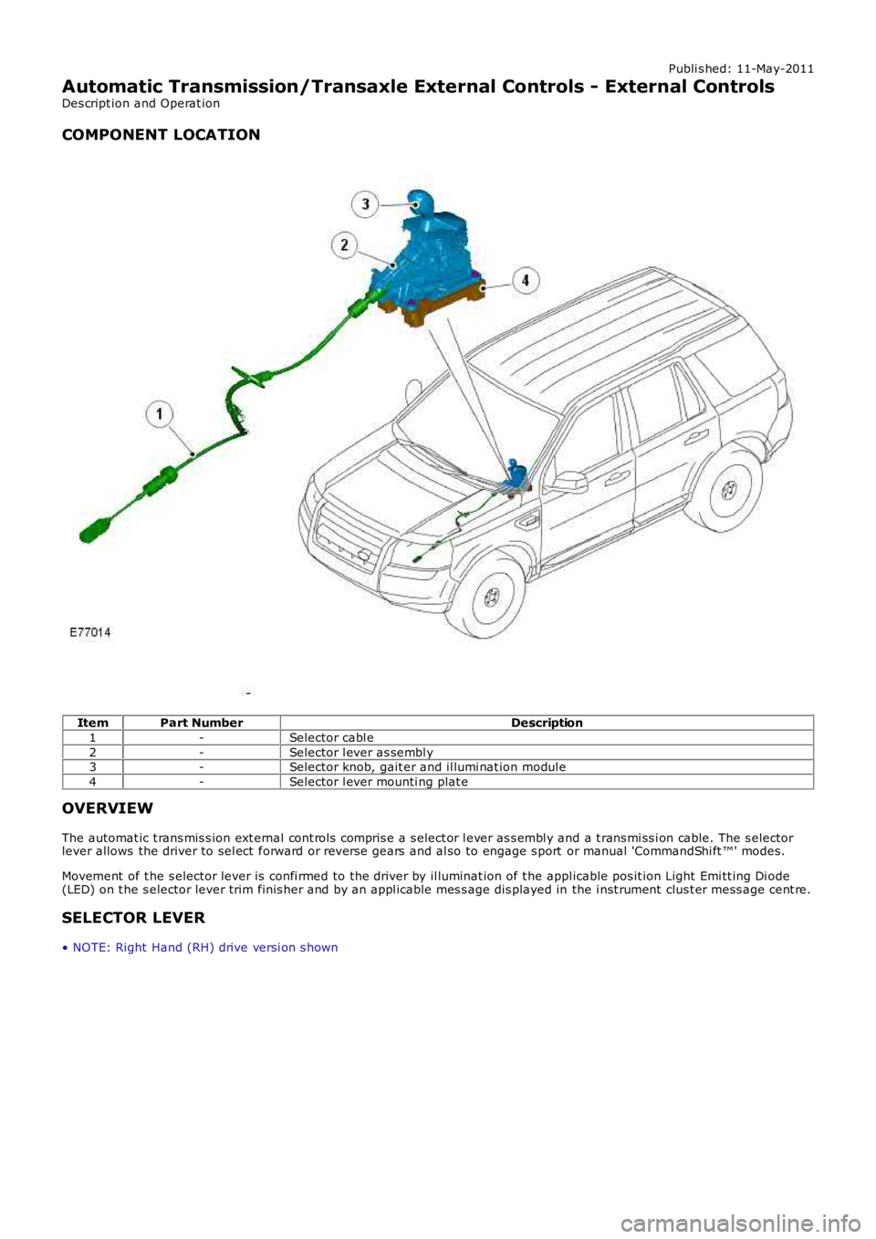
COMPONENT LOCATION
ItemPart NumberDescription
1-Selector cabl e
2-Selector l ever as sembl y3-Selector knob, gait er and il lumi nat ion modul e
4-Selector l ever mounti ng plat e
OVERVIEW
The automat ic t rans mis s ion ext ernal cont rols compris e a s elect or l ever as s embl y and a t rans mi ss i on cable. The s electorlever allows the driver to sel ect forward or revers e gears and al so to engage s port or manual 'CommandShi ft ™' modes.
Movement of t he s elector lever is confi rmed to the driver by il luminat ion of t he appl icable pos it ion Light Emi tt ing Di ode(LED) on t he s elector lever trim finis her and by an appl icable mes s age dis played in the i nst rument clus t er mess age cent re.
SELECTOR LEVER
• NOTE: Right Hand (RH) drive versi on s hown
Page 1370 of 3229
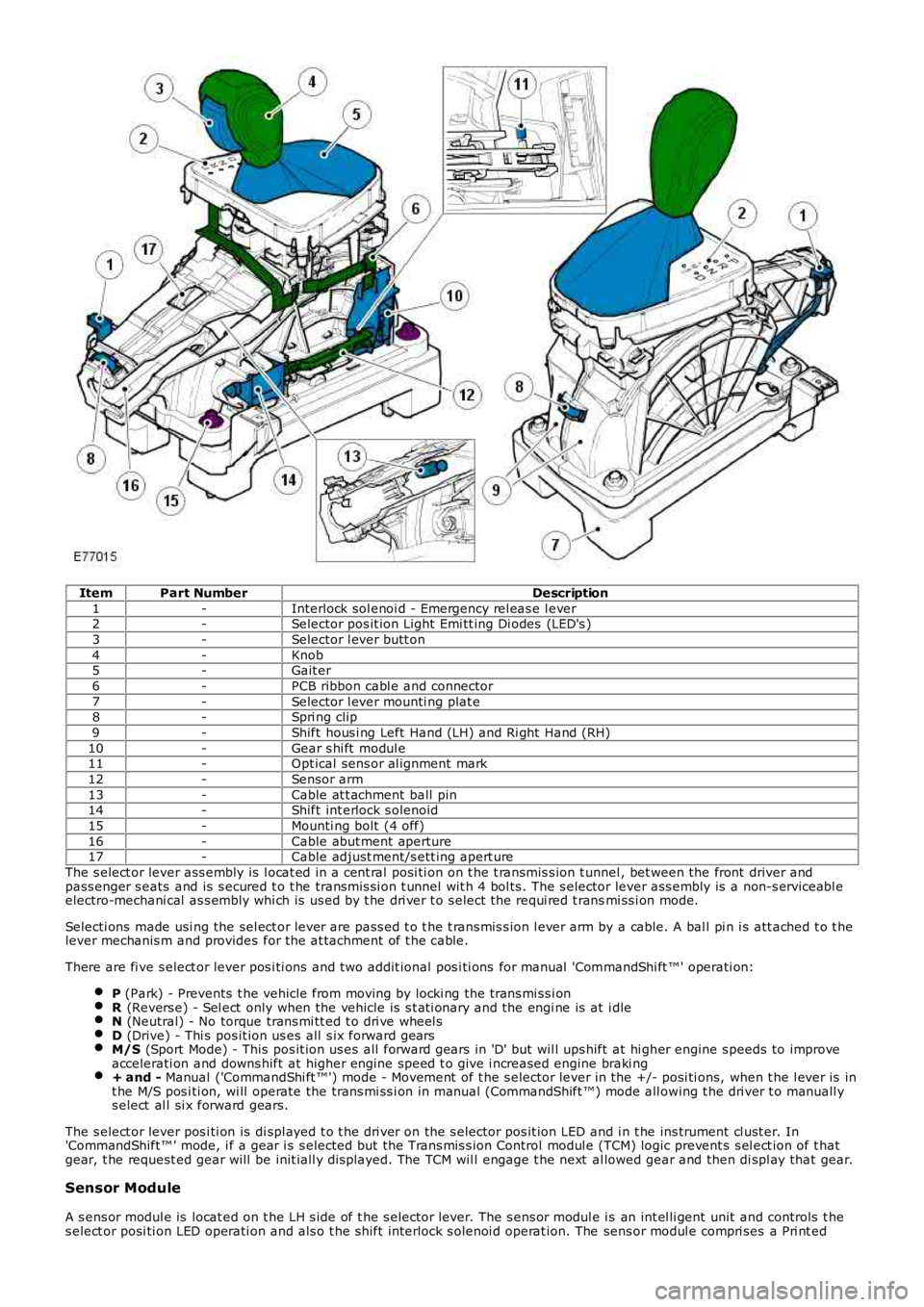
ItemPart NumberDescription
1-Interlock sol enoi d - Emergency rel eas e l ever2-Selector pos it ion Light Emi tt ing Di odes (LED's )
3-Selector l ever butt on
4-Knob5-Gait er
6-PCB ribbon cabl e and connector
7-Selector l ever mounti ng plat e8-Spri ng clip
9-Shift hous i ng Left Hand (LH) and Ri ght Hand (RH)
10-Gear s hi ft modul e11-Opt ical sens or al ignment mark
12-Sensor arm
13-Cable at t achment ball pin14-Shift int erlock s olenoid
15-Mounti ng bolt (4 off)
16-Cable abut ment aperture17-Cable adjust ment/s ett ing apert ure
The s elect or lever ass embly is l ocat ed in a cent ral posi ti on on t he t ransmis s ion t unnel , bet ween the front driver andpass enger s eats and is s ecured t o t he transmis si on t unnel wit h 4 bol ts . The s elector lever ass embly is a non-s erviceabl eelectro-mechani cal as s embly whi ch is us ed by t he dri ver t o s elect the requi red t ransmi ss i on mode.
Selecti ons made usi ng the sel ect or lever are pass ed t o t he t rans mis s ion l ever arm by a cable. A bal l pi n i s att ached t o t helever mechanis m and provides for the at tachment of t he cable.
There are fi ve s elect or lever pos i ti ons and t wo addit ional pos i ti ons for manual 'CommandShi ft ™' operati on:
P (Park) - Prevents t he vehicle from moving by locki ng the trans mi ss i onR (Revers e) - Sel ect only when the vehicle is s t ati onary and the engi ne is at i dleN (Neutral) - No torque trans mi tt ed t o dri ve wheel sD (Drive) - Thi s pos it ion us es all s ix forward gearsM/S (Sport Mode) - This pos it ion us es all forward gears in 'D' but wil l ups hift at hi gher engine s peeds to improveaccelerati on and downs hift at higher engine speed t o give i ncreased engine braki ng+ and - Manual ('CommandShi ft ™') mode - Movement of t he s elector lever in the +/- posi ti ons, when t he l ever is int he M/S pos i ti on, wi ll operate the trans mi ss i on in manual (CommandShift ™) mode all owing t he dri ver t o manuall ys elect al l si x forward gears.
The s elect or lever pos i ti on is di spl ayed t o t he dri ver on the s elector pos it ion LED and i n t he ins trument cl ust er. In'CommandShift™ ' mode, i f a gear i s s elected but t he Trans mis s ion Control modul e (TCM) logic prevent s s el ect ion of t hatgear, t he request ed gear will be init iall y dis played. The TCM wil l engage t he next al lowed gear and then di spl ay that gear.
Sensor Module
A s ens or modul e is locat ed on t he LH s ide of t he s elector lever. The s ens or modul e is an int el li gent unit and controls t hes elect or posi ti on LED operati on and als o t he s hift interlock s olenoi d operat ion. The sens or modul e compri ses a Pri nt ed
Page 1621 of 3229
Publi s hed: 11-May-2011
Speed Control - I6 3.2L Petrol - Speed Control Deactivator Switch
Removal and Inst all ati on
Removal
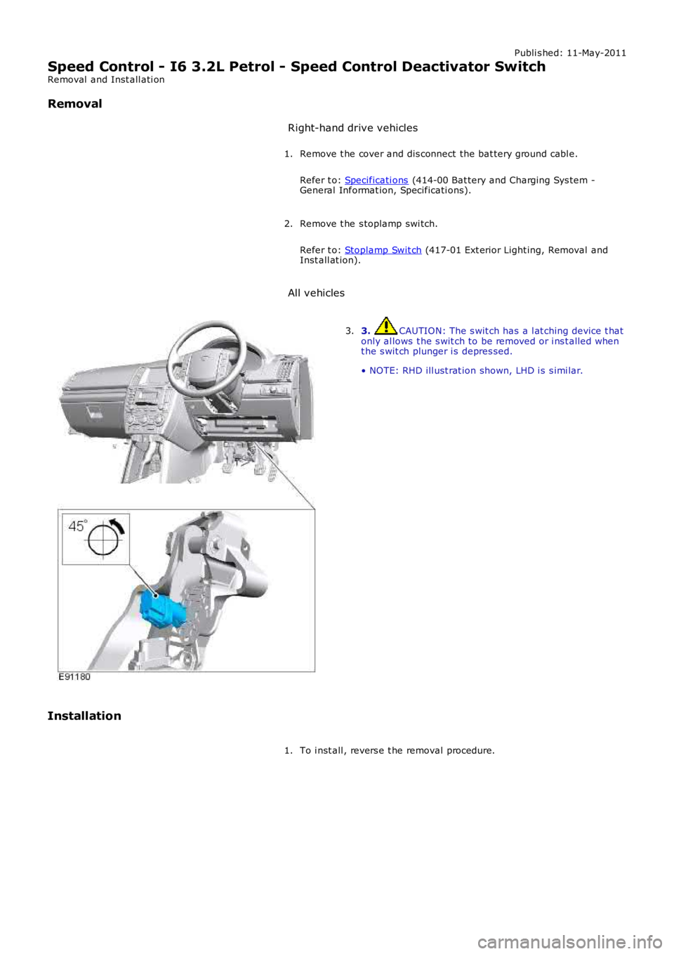
Right-hand drive vehicles
Remove t he cover and dis connect the bat tery ground cabl e.
Refer t o: Specificati ons (414-00 Bat tery and Charging Sys tem -General Informat ion, Specificati ons).
1.
Remove t he s toplamp swi tch.
Refer t o: Stoplamp Swit ch (417-01 Ext erior Light ing, Removal andInst all at ion).
2.
All vehicles
3. CAUTION: The s wit ch has a l at ching device t hatonly al lows t he s wit ch to be removed or i ns t alled whent he s wit ch plunger i s depres sed.
• NOTE: RHD ill ust rat ion shown, LHD i s s imi lar.
3.
Installation
To i nst all , revers e t he removal procedure.1.
Page 1627 of 3229
Publi s hed: 11-May-2011
Speed Control - TD4 2.2L Diesel - Speed Control Deactivator Switch
Removal and Inst all ati on
Removal Right-hand drive vehicles
Remove t he cover and dis connect the bat tery ground cabl e.
Refer t o: Specificati ons (414-00 Bat tery and Charging Sys tem -
General Informat ion, Specificati ons).
1.
Remove t he s toplamp swi tch.
Refer t o: Stoplamp Swit ch (417-01 Ext erior Light ing, Removal and
Inst all at ion).
2.
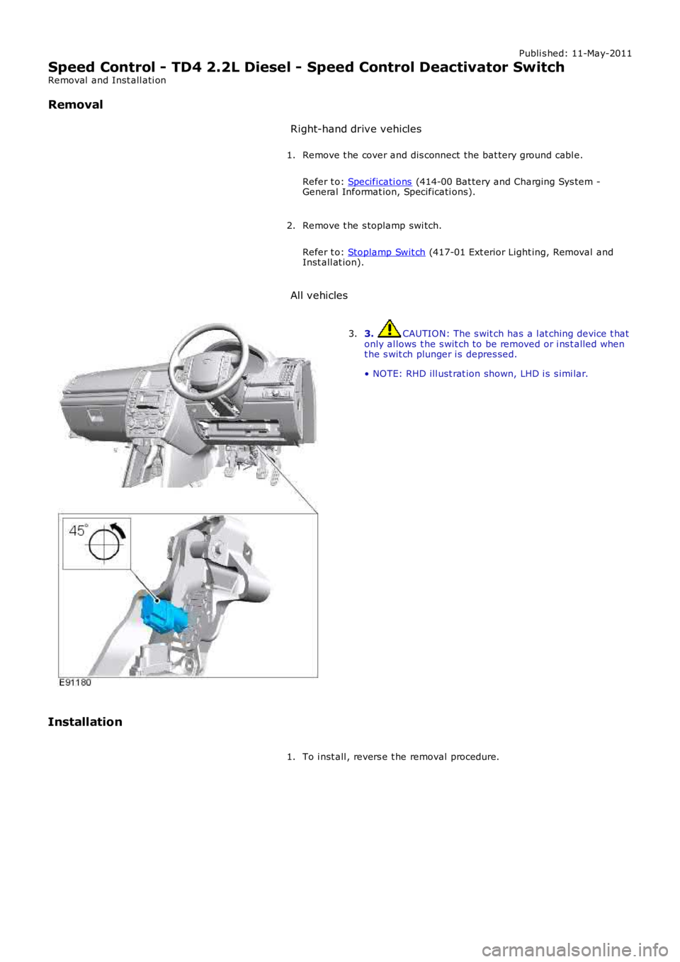
All vehicles 3. CAUTION: The s wit ch has a l at ching device t hat
only al lows t he s wit ch to be removed or i ns t alled when
t he s wit ch plunger i s depres sed.
• NOTE: RHD ill ust rat ion shown, LHD i s s imi lar.
3.
Installation To i nst all , revers e t he removal procedure.
1.
Page 1649 of 3229
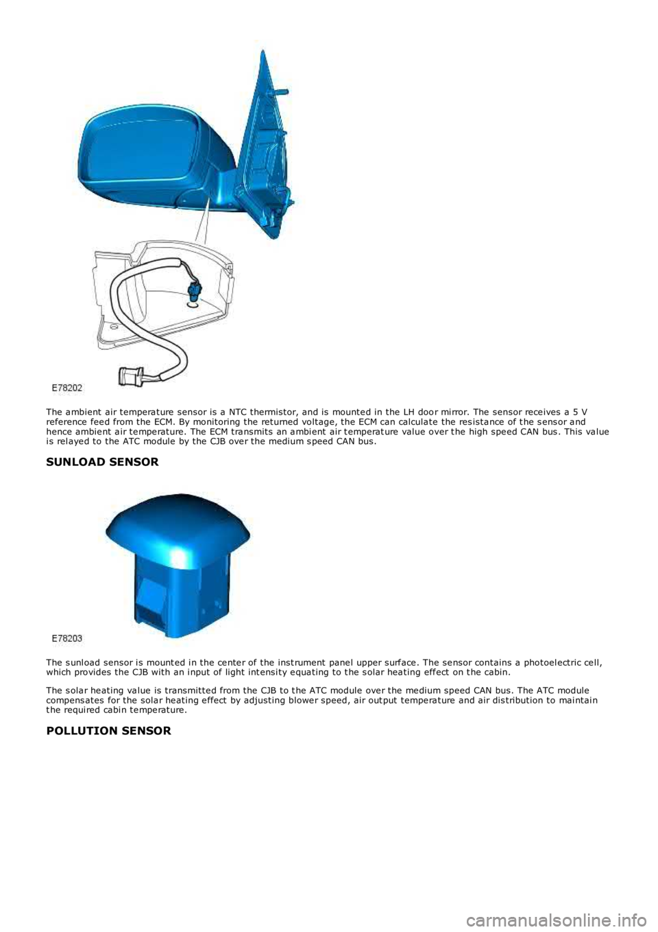
The a mbient air tempera ture sensor is a NTC thermi stor, and is mounte d in the LH door mi rror. The sensor rece ives a 5 Vreference fee d from the ECM. By monitoring the returned voltage, the ECM can calculate the res ista nce of t he s ens or a ndhence ambie nt a ir te mpe rature. The ECM tra nsmits an a mbi ent air t emperat ure value over t he high spe ed CAN bus . This va luei s rel aye d to the ATC module by the CJB ove r the medium s peed CAN bus.
SUNLOAD SENSOR
The s unl oad sensor i s mount ed i n the ce nte r of the inst rument pane l upper surf ace . The se nsor contains a photoel ectric ce ll,which provides the CJB with an i nput of light int ensi ty e qua ting to t he s olar hea ting eff ect on t he cabin.
The s ola r he ating va lue is transmitte d from the CJB to t he ATC module ove r the me dium speed CAN bus. The ATC modulecompens ates for the sola r he ating e ffect by adjusting blowe r speed, air out put tempera ture and air dis tribution to mai ntai nt he requi red cabi n te mpe rature.
POLLUTION SENSOR
Page 1652 of 3229
14-Cabin t empera ture sensor15-Eva porator temperature se nsor16-ECM17-ATC modul e18-Fus e 27, CJB19-Blower mot or control module20-Sunloa d se nsor21-Fus ible link 17, BJB
PRINCIPLES OF OPERATION
Intake Air Control - Single Zone Manual System
The i ntake a ir source is cont rolle d manually by press ing the fres h/re circulat ed a ir switch located on the control panel. W he npress ed, the ATC module wil l illuminate the swi tch t ell-tale Light Emitti ng Diode (LED) and clos e the a ir intake door. A secondpress of the swit ch will caus e the ATC module to extinguish the swi tch LED and ope n the a ir intake door, a llowing fres h ai r toe nte r the cabin.
• NO TE: The ATC module wil l reduce the amount of fres h ai r ent ering the ca bin to reduce the ra m e ffect ca used by forwardmoti on of the ve hicle .
W he n recirculate d ai r is sele cted, the ATC module will re turn the air int ake door to the ope n position a fter a pe riod of 3minutes. Thi s he lps prevent mis ting within t he cabin. The 3 minute time pe riod for reci rcula ted air can be overridde n bypress ing and hol ding the fre sh/re circulat ed a ir s witch until t he s witch LED fl ashes 3 times. The air inta ke door will now remainclose d until t he next drive cycle.
The ATC module controls the pos ition of the air inta ke door by providing LIN bus messa ges to t he a ir intake door s teppermotor. A Hal l eff ect sens or l ocat ed withi n the st epper motor inf orms the ATC module that move me nt of the ste ppe r motor ist aking pl ace.
Intake Air Control - Dual Zone Automatic System
The i ntake a ir source is cont rolle d automatically unl ess overridden by press ing the fresh/recirculate d ai r switch loca ted on thecontrol pane l. Under aut oma tic control, t he ATC module det ermi nes the require d position of the air inta ke door usi ng it s'comfort' algorithm based on inputs from the ambient ai r tempe rature s ensor and the ca bin temperature se nsor.
W he n the ve hicle firs t enters power mode 6 (ignition on), the te ll-ta le LED on t he fresh/recirculated air swi tch will bei lluminat ed a nd t he air intake source wil l be aut oma tica lly controlle d by the ATC modul e. The ATC module will cont rol t hei ntake ai r source accordi ng t o ambie nt a ir te mpe rature a nd requeste d ca bin temperature. The intake ai r door will be opene d toa llow fre sh a ir into t he cabin, alt hough a small a mount of re circulat ed a ir will a lso be prese nt.
• NO TE: The ATC module wil l reduce the amount of fres h ai r ent ering the ca bin to reduce the ra m e ffect ca used by forwardmoti on of the ve hicle .
A single pres s of the fres h/re circulat ed a ir s witch wi ll extinguish the tel l-tal e LED. The ATC module will now close t he a iri ntake door a nd provide only recircul ated air into the cabin f or a period of 3 minutes . Af ter this peri od, the ATC module wil lreturn the ai r int ake door to automa tic control. This helps preve nt misti ng withi n the ca bin.
A second pre ss of the fre sh/recircula ted air s wit ch will a lso return the intake air source to a utomati c control and ill uminate thet ell-t ale LED.
The 3 mi nute time period for recircul ated air can be ove rridden by press ing and holding the fres h/re circulate d a ir switch untilt he s witch LED fl ashes 3 times. The air inta ke door will now remain clos ed unti l the next drive cycle .
The ATC module controls the pos ition of the air inta ke door by providing LIN bus messa ges to t he a ir intake door s teppermotor. A Hal l eff ect sens or l ocat ed withi n the st epper motor inf orms the ATC module that move me nt of the ste ppe r motor ist aking pl ace.
Intake Air Control - Dual Zone Automatic System with Pollution Sensor
The i ntake a ir source is cont rolle d automatically unl ess overridden by press ing the fresh/recirculate d ai r switch loca ted on thecontrol pane l. Under aut oma tic control, t he ATC module det ermi nes the require d position of the air inta ke door usi ng it s'comfort' algorithm based on inputs from the ambient ai r tempe rature s ensor, t he cabin temperature se nsor and the pollut ions ens or.
• NO TE: The ATC module wil l reduce the amount of fres h ai r ent ering the ca bin to reduce the ra m e ffect ca used by forwardmoti on of the ve hicle .
W he n the ve hicle firs t enters power mode 6 (ignition on), the 'AUTO ' te ll-ta le LED on the fresh/reci rcul ated air swit ch will bei lluminat ed a nd t he air intake source wil l be aut oma tica lly controlle d by the ATC modul e. A single pres s of thef resh/recircul ated air swi tch will exti ngui sh t he 'AUTO' te ll-t ale LED and illumina te t he 'MAN' te ll-ta le LED. The ATC modulewill now clos e the ai r int ake door and provide only recirculat ed a ir into t he cabi n for a period of 3 minutes. Afte r this period,t he ATC module will return t he a ir intake door to automatic cont rol. This he lps prevent mist ing within t he cabin.
A second pre ss of the fre sh/recircula ted air s wit ch will e xtinguis h both t he 'AUTO' a nd 'MAN' tel l-ta le LED's . The ATC modulewill now cont rol the inta ke a ir source according t o a mbie nt a ir te mperat ure and request ed cabin tempe rature. The a ir intakedoor will be opened to a llow fres h a ir int o the ca bin, but a s mal l amount of reci rcul ated air will also be pre sent . The amountof re circulate d ai r is dete rmi ned by t he ATC module using it s 'comfort' a lgorithm based on i nputs from the ambient airt emperat ure sensor and the cabi n te mpe rature s ens or.
A thi rd press of t he f resh/recirculate d ai r switch returns the air i ntake s ource to aut oma tic cont rol a nd will illumina te the'AUTO' te ll-ta le LED.
The 3 mi nute time period for recircul ated air can be ove rridden by press ing and holding the fres h/re circulate d a ir switch untilt he s witch LED's flas h 3 time s. The air intake door will now remain clos ed until the next dri ve cycle .
The ATC module controls the pos ition of the air inta ke door by providing LIN bus messa ges to t he a ir intake door s tepper
Page 1747 of 3229
The ambient air t emperat ure s ensor i s a Negati ve Temperature Co-effi ci ent (NTC) thermis t or, and is mount ed in the LeftHand (LH) door mi rror. The s ens or is connect ed t o the Engi ne Cont rol Module (ECM) which t rans mit s an ambi ent ai rt emperature val ue over t he high speed CAN bus . This value i s rel ayed to the ATC modul e by t he Cent ral Junct ion Box (CJB)over t he medium s peed CAN bus.For addit ional informat ion, refer t o: Cont rol Component s (412-01 Cli mat e Cont rol , Descripti on and Operat ion).
REMOTE CONTROL COMPONENTS - VEHICLES FROM 2009MY WITH FFBH REMOTE
CONTROL
The addi ti on of remot e control retai ns the FFBH component s fit ted t o pre 2009MY vehicl es wit h t he addi ti on of thefol lowing components :
FFBH wit h upgraded s oft ware and cali brat ionFFBH remot e handsetFFBH remot e receiverRecei ver power, communicati on and antenna harnes sesAntenna mat chi ng unit harnes s to connect recei ver co-axial cable t o exis t ing DAB antenna in s ide window.
FFBH Remote Handset
ItemPart NumberDescription
1-On butt on2-Off butt on
3-LED operat ion indicator
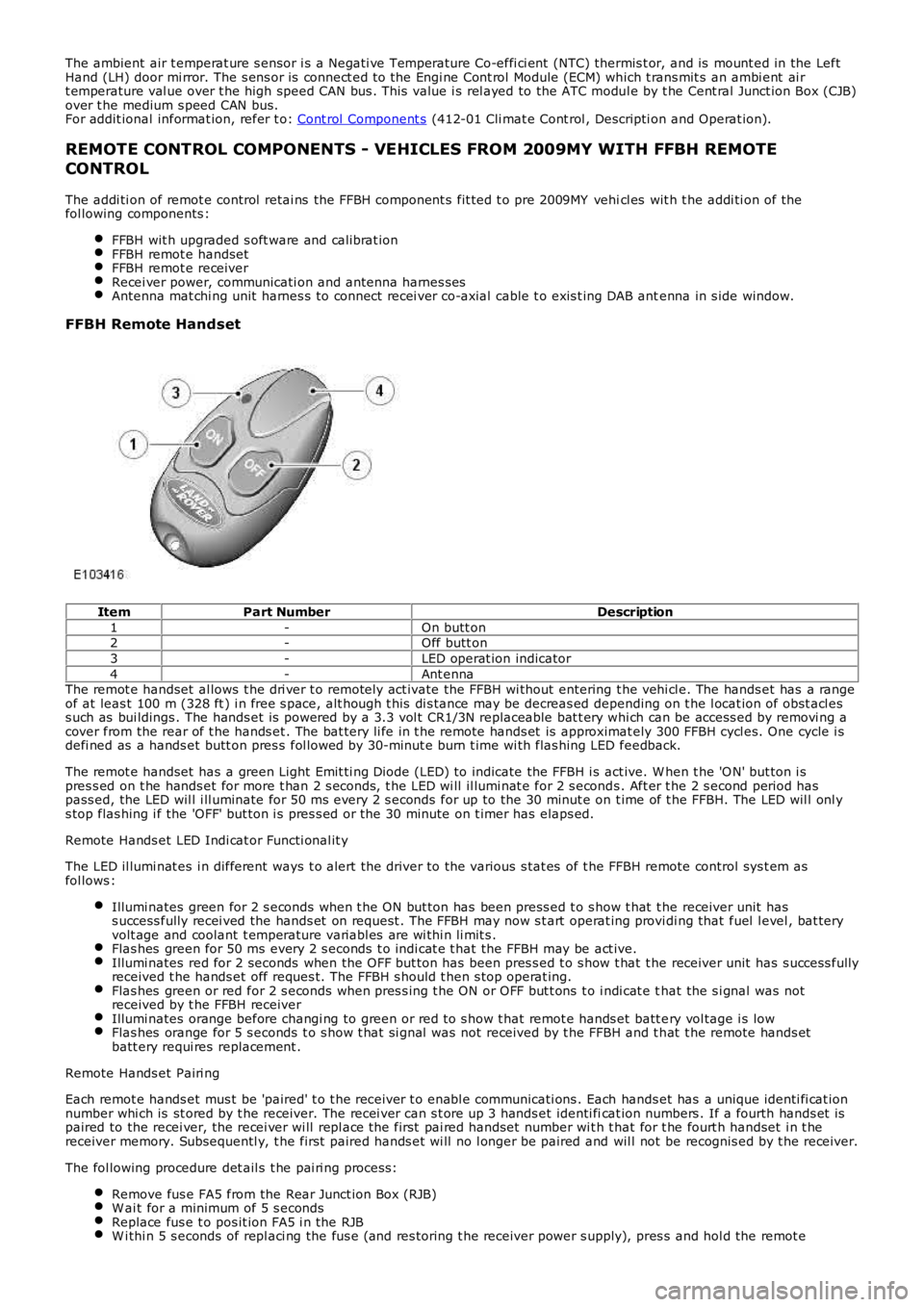
4-Ant ennaThe remot e handset al lows t he dri ver t o remotely act ivate the FFBH wi thout entering t he vehi cl e. The hands et has a rangeof at leas t 100 m (328 ft ) i n free s pace, alt hough t his di s tance may be decreas ed depending on t he l ocat ion of obst acl ess uch as bui ldings . The hands et is powered by a 3.3 vol t CR1/3N replaceable bat t ery whi ch can be access ed by removi ng acover from the rear of t he hands et . The bat tery li fe in t he remote hands et is approximat ely 300 FFBH cycl es. One cycle i sdefi ned as a hands et butt on pres s fol lowed by 30-minut e burn t ime wi th flas hing LED feedback.
The remot e handset has a green Light Emit ti ng Diode (LED) to indicate the FFBH i s act ive. W hen t he 'O N' but ton i spres s ed on t he hands et for more t han 2 s econds, t he LED wi ll il lumi nat e for 2 s econds . Aft er t he 2 s econd period haspass ed, the LED wil l i ll uminate for 50 ms every 2 s econds for up to the 30 minut e on t ime of t he FFBH. The LED wil l onl ys top flas hing i f the 'OFF' but ton i s pres s ed or the 30 minute on t imer has elaps ed.
Remote Hands et LED Indi cat or Functi onal it y
The LED il lumi nat es i n different ways t o alert the driver to the various s tat es of the FFBH remote control sys t em asfol lows :
Illumi nates green for 2 s econds when t he ON but ton has been press ed t o s how t hat t he receiver unit hass uccess fully recei ved the hands et on request . The FFBH may now s t art operat ing providi ng that fuel l evel , bat teryvolt age and coolant t emperature variabl es are wi thi n li mit s .Flas hes green for 50 ms every 2 s econds t o i ndi cat e t hat the FFBH may be act ive.Illumi nates red for 2 seconds when the OFF but ton has been pres s ed t o s how t hat t he receiver unit has s uccess fullyreceived t he hands et off reques t. The FFBH s hould t hen s top operat ing.Flas hes green or red for 2 s econds when pres s ing t he ON or OFF but t ons t o i ndi cat e that the s i gnal was notreceived by t he FFBH receiverIllumi nates orange before changi ng to green or red to s how t hat remot e hands et batt ery vol tage i s lowFlas hes orange for 5 s econds t o s how t hat si gnal was not received by t he FFBH and t hat t he remote hands etbatt ery requi res replacement .
Remote Hands et Pairi ng
Each remot e hands et mus t be 'paired' t o t he receiver t o enabl e communicati ons . Each hands et has a unique identi fi cat ionnumber whi ch is st ored by t he receiver. The recei ver can s t ore up 3 hands et identi ficat ion numbers . If a fourth hands et ispaired to the recei ver, the recei ver wi ll repl ace the first pai red handset number wit h t hat for t he fourt h handset i n t hereceiver memory. Subsequentl y, t he first paired hands et wi ll no l onger be paired and wil l not be recognis ed by t he receiver.
The fol lowing procedure det ail s t he pai ri ng process :
Remove fus e FA5 from the Rear Junct ion Box (RJB)W ai t for a minimum of 5 s econdsReplace fus e t o pos it ion FA5 i n the RJBW i thi n 5 s econds of repl aci ng the fus e (and res toring t he receiver power s upply), pres s and hol d the remot e