2006 LAND ROVER FRELANDER 2 light
[x] Cancel search: lightPage 1870 of 3229
ClockAntenna powerLight Emit t ing Di ode (LED) il lumi nat ion.
In transi t mode t he CAN port and t he ON/OFF s wit ch are t he only ci rcuit s that are left act ive.
The CAN port is l eft open to allow the EXIT from transi t mode s ignal to be received. The O N/OFF s wit ch is left act ive t oall ow feedback to the driver vi a t he head uni t LCD (liqui d crys tal dis play), t hat the unit is i n t ransi t mode s houl d t he dri veratt empt t o power up the head unit . This wi ll only occur when t he vehicle engine is runni ng and the bat tery is above 12.3Volt s.
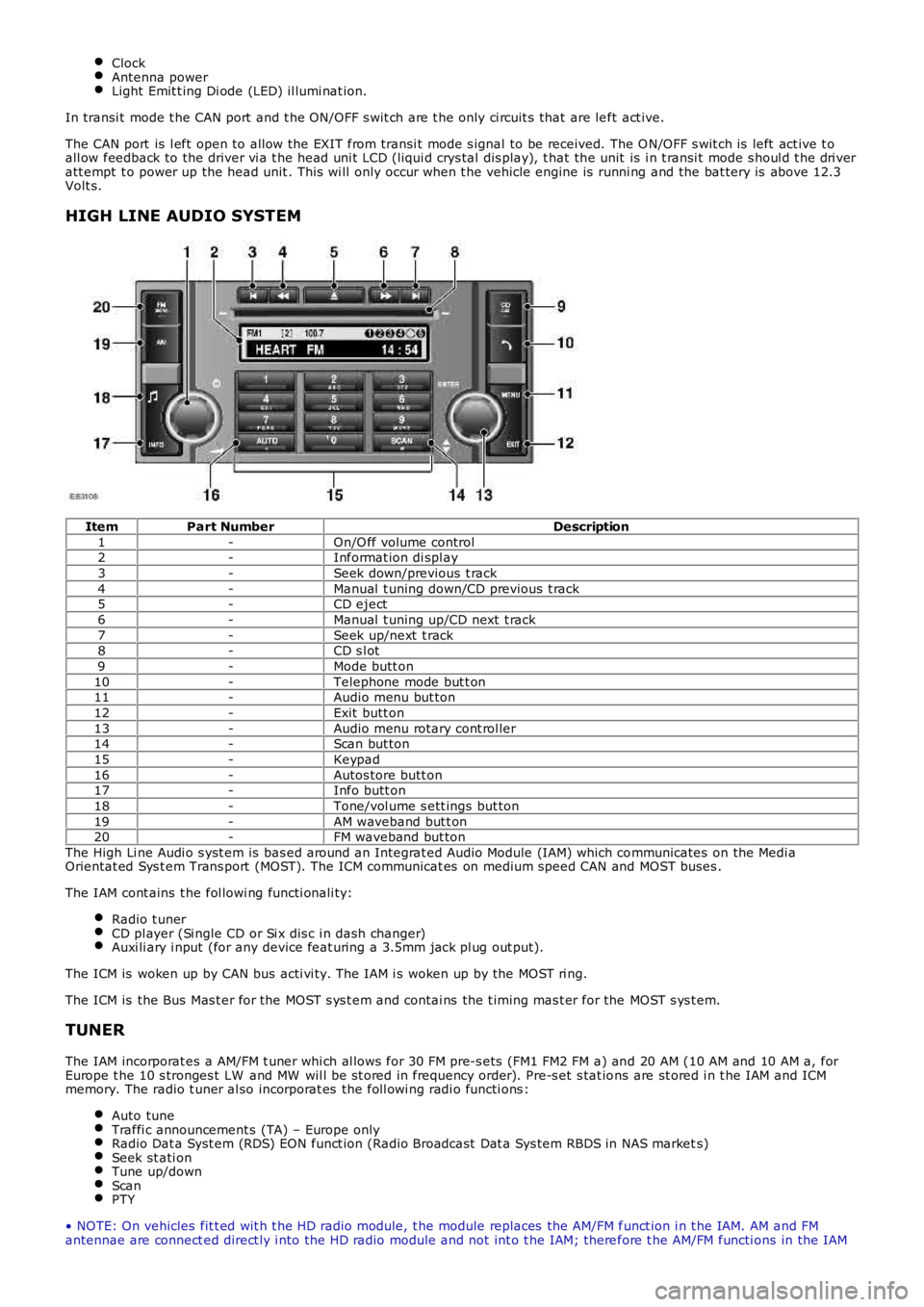
HIGH LINE AUDIO SYSTEM
ItemPart NumberDescription
1-On/O ff volume control2-Informat ion di spl ay
3-Seek down/previous t rack
4-Manual t uning down/CD previous t rack5-CD eject
6-Manual t uning up/CD next t rack
7-Seek up/next t rack8-CD s l ot
9-Mode butt on
10-Telephone mode but t on11-Audio menu but ton
12-Exit butt on
13-Audio menu rotary cont rol ler14-Scan but ton
15-Keypad
16-Autos tore butt on17-Info butt on
18-Tone/vol ume s ett ings but ton
19-AM waveband but t on20-FM waveband but ton
The High Li ne Audi o s yst em is bas ed around an Integrat ed Audio Module (IAM) which communicates on the Medi aOrientat ed Sys t em Trans port (MOST). The ICM communicat es on medium speed CAN and MOST buses .
The IAM cont ains t he fol lowi ng functi onali ty:
Radio t unerCD pl ayer (Si ngle CD or Si x dis c i n dash changer)Auxi li ary i nput (for any device feat uring a 3.5mm jack pl ug out put).
The ICM is woken up by CAN bus acti vi ty. The IAM i s woken up by the MOST ri ng.
The ICM is the Bus Mas t er for the MOST s ys t em and contai ns the t iming mas t er for the MOST s ys t em.
TUNER
The IAM incorporat es a AM/FM t uner whi ch al lows for 30 FM pre-s ets (FM1 FM2 FM a) and 20 AM (10 AM and 10 AM a, forEurope t he 10 s tronges t LW and MW wil l be st ored in frequency order). Pre-s et s tat ions are st ored i n t he IAM and ICMmemory. The radio t uner al so incorporat es the foll owi ng radi o functi ons :
Auto tuneTraffi c announcement s (TA) – Europe onlyRadio Dat a Syst em (RDS) EON funct ion (Radio Broadcast Dat a Sys tem RBDS in NAS markets)Seek st ati onTune up/downScanPTY
• NOTE: On vehicles fit t ed wit h t he HD radio module, t he module replaces the AM/FM funct ion i n t he IAM. AM and FMantennae are connect ed direct ly i nto the HD radio module and not int o t he IAM; therefore t he AM/FM functi ons in the IAM
Page 1916 of 3229
Publi s hed: 11-May-2011
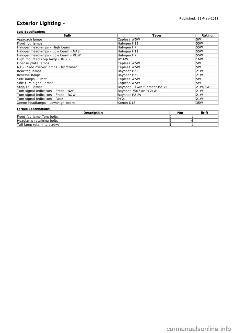
Exterior Lighting -
Bulb SpecificationsBulbT ypeRating
Approach lampsCaples s W 5W5W
Front fog lampsHalogen H1155WHalogen headlamps - Hi gh beamHalogen H755W
Halogen headlamps - Low beam - NASHalogen H1155W
Halogen headlamps - Low beam - ROWHalogen H755WHi gh mount ed s t op lamp (HMSL)W 16W16W
License plate lampsCaples s W 5W5W
NAS - Si de marker lamps - front /rearCaples s W 5W5WRear fog l ampsBayonet P2121W
Revers e lampsBayonet P2121W
Side lamps - FrontCaples s W 5W5WSide turn s ignal l ampsCaples s W 5W5W
St op/Tai l lampsBayonet - Twi n fi lament P21/521W /5W
Turn si gnal i ndi cat ors - Front - NASBayonet 7507 or PY 21W21WTurn si gnal i ndi cat ors - Front - RO WBayonet P21W21W
Turn si gnal i ndi cat ors - RearPY 2121W
Xenon headl amps - Low/Hi gh beamXenon D1S35W
Torque Specifications
DescriptionNmlb-ftFront fog lamp Torx bolt s21
Headlamp retai ni ng bolt s64
Tail l amp ret aining screws11
Page 1917 of 3229
Publi s hed: 11-May-2011
Exterior Lighting - Exterior Lighting
Des cript ion and Operat ion
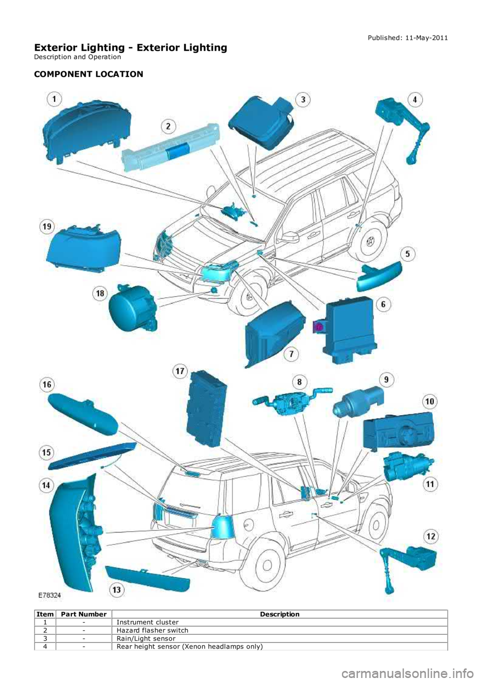
COMPONENT LOCATION
ItemPart NumberDescription1-Inst rument clus t er
2-Hazard flas her swi tch
3-Rain/Light sens or4-Rear hei ght sens or (Xenon headl amps only)
Page 1918 of 3229
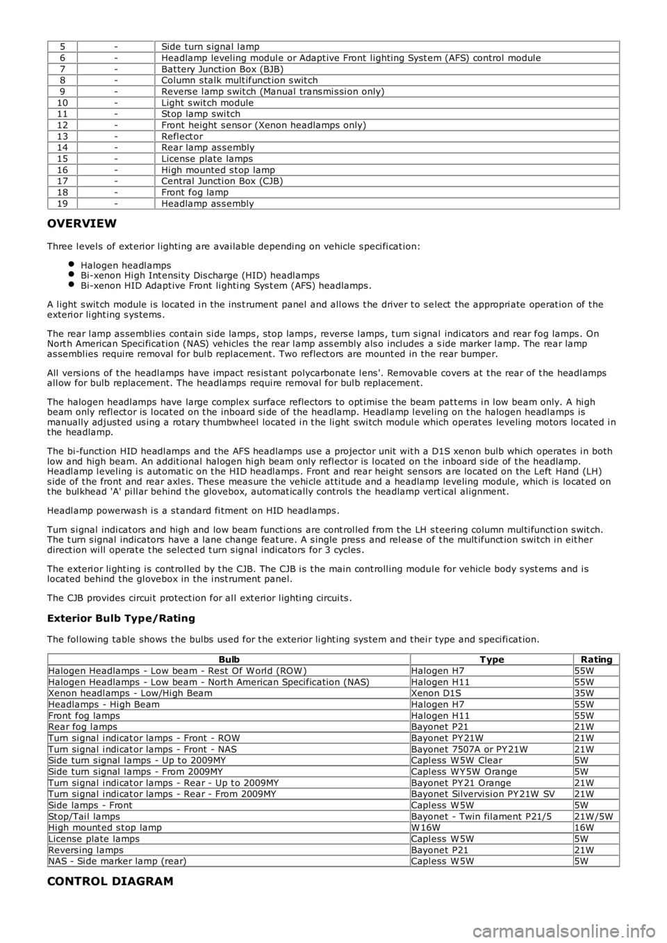
5-Side turn s ignal l amp
6-Headlamp level ing modul e or Adapt ive Front l ighti ng Sys t em (AFS) control modul e
7-Bat tery Juncti on Box (BJB)8-Column s talk mult ifunct ion s wit ch
9-Revers e l amp s wit ch (Manual trans mi s si on only)
10-Light s wit ch module11-St op lamp swi tch
12-Front height s ens or (Xenon headlamps only)
13-Refl ect or14-Rear lamp as s embly
15-License plate lamps
16-Hi gh mounted s t op lamp17-Central Juncti on Box (CJB)
18-Front fog lamp
19-Headlamp as s embly
OVERVIEW
Three l evel s of ext eri or l ighti ng are avai lable dependi ng on vehicle s peci fi cat ion:
Halogen headl ampsBi-xenon Hi gh Int ensi ty Dis charge (HID) headl ampsBi-xenon HID Adapt ive Front li ghti ng Sys t em (AFS) headlamps .
A l ight s wit ch module i s located i n t he ins t rument panel and all ows t he driver t o s elect the appropri ate operat ion of t heexteri or li ght ing s ys tems .
The rear l amp as sembl ies cont ain si de lamps , s top lamps , revers e l amps , t urn s i gnal indi cat ors and rear fog lamps . OnNort h American Speci ficat ion (NAS) vehicles the rear l amp as s embly als o incl udes a side marker l amp. The rear lampas sembl ies requi re removal for bul b repl acement. Two reflect ors are mount ed in the rear bumper.
All vers ions of t he headl amps have impact res is t ant polycarbonat e l ens '. Removable covers at t he rear of t he headl ampsall ow for bulb replacement. The headlamps requi re removal for bul b repl acement.
The halogen headl amps have large complex surface reflectors to opt imis e t he beam patt erns i n l ow beam only. A hi ghbeam only refl ect or is l ocat ed on t he inboard s i de of the headlamp. Headl amp l evel ing on t he halogen headl amps ismanually adjust ed us ing a rot ary t humbwheel located i n t he li ght swi tch modul e which operat es leveling motors located i nt he headlamp.
The bi-functi on HID headl amps and the AFS headlamps us e a projector unit wit h a D1S xenon bulb whi ch operates i n bothlow and high beam. An addit ional hal ogen hi gh beam only refl ect or is l ocat ed on t he inboard s ide of t he headlamp.Headl amp l evel ing i s aut omat ic on t he HID headl amps . Front and rear hei ght sens ors are located on the Left Hand (LH)s ide of t he front and rear axl es. Thes e meas ure t he vehi cle at ti tude and a headlamp leveling modul e, which is locat ed ont he bul khead 'A' pi ll ar behind t he glovebox, aut omat icall y cont rol s t he headlamp vert ical al ignment.
Headl amp powerwas h i s a s t andard fi tment on HID headlamps .
Turn s i gnal indi cat ors and high and low beam functi ons are cont rol led from t he LH s teeri ng column mul ti functi on s wit ch.The t urn s ignal indicators have a lane change feat ure. A s ingle pres s and rel eas e of t he mult ifunct ion s wi tch i n eit herdirect ion wi ll operat e t he sel ect ed t urn s ignal indicators for 3 cycles .
The exteri or li ght ing i s cont rol led by t he CJB. The CJB i s t he main cont roll ing modul e for vehicle body s yst ems and i slocated behind the gl ovebox in the i nst rument panel.
The CJB provides circui t protect ion for al l ext eri or l ighti ng circui ts .
Exterior Bulb Typ e/Rating
The fol lowing table shows t he bulbs us ed for t he exterior li ght ing sys tem and t hei r type and s peci fi cat ion.
BulbT ypeRating
Halogen Headlamps - Low beam - Rest O f W orl d (ROW )Halogen H755W
Halogen Headlamps - Low beam - Nort h American Specificati on (NAS)Halogen H1155WXenon headl amps - Low/Hi gh BeamXenon D1S35W
Headlamps - Hi gh BeamHalogen H755W
Front fog lampsHalogen H1155WRear fog l ampsBayonet P2121W
Turn si gnal i ndi cat or lamps - Front - ROWBayonet PY 21W21W
Turn si gnal i ndi cat or lamps - Front - NASBayonet 7507A or PY 21W21WSide turn s ignal l amps - Up t o 2009MYCapl ess W 5W Clear5W
Side turn s ignal l amps - From 2009MYCapl ess W Y 5W Orange5W
Turn si gnal i ndi cat or lamps - Rear - Up t o 2009MYBayonet PY 21 Orange21WTurn si gnal i ndi cat or lamps - Rear - From 2009MYBayonet Silvervi si on PY 21W SV21W
Side lamps - FrontCapl ess W 5W5W
St op/Tai l lampsBayonet - Twin fil ament P21/521W /5WHi gh mount ed s t op lampW 16W16W
License plate lampsCapl ess W 5W5W
Revers ing l ampsBayonet P2121WNAS - Si de marker lamp (rear)Capl ess W 5W5W
CONTROL DIAGRAM
Page 1920 of 3229
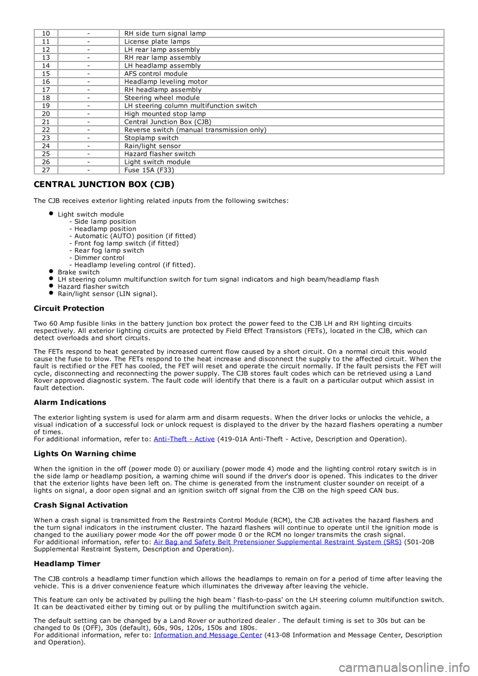
10-RH s i de turn s ignal lamp
11-Licens e pl ate lamps
12-LH rear l amp as s embl y13-RH rear lamp as s embly
14-LH headlamp as s embly
15-AFS cont rol module16-Headl amp l evel ing mot or
17-RH headlamp as s embly
18-Steering wheel modul e19-LH s t eering column mult ifunct ion s wit ch
20-High mount ed s top lamp
21-Central Junct ion Box (CJB)22-Revers e s wit ch (manual transmis si on only)
23-Stoplamp s wit ch
24-Rain/light s ensor25-Hazard flas her s wi tch
26-Light s wit ch modul e
27-Fuse 15A (F33)
CENTRAL JUNCTION BOX (CJB)
The CJB receives exteri or li ght ing relat ed inputs from t he fol lowing s wi tches:
Light s wit ch modul e- Side l amp pos it ion- Headlamp pos it ion- Automat ic (AUTO) posi ti on (if fi tt ed)- Front fog lamp swi tch (if fit ted)- Rear fog l amp s wit ch- Dimmer cont rol- Headlamp l evel ing control (if fit ted).Brake s wi tchLH s t eering column mult ifunct ion s wit ch for t urn si gnal i ndi cat ors and hi gh beam/headl amp flas hHazard flas her s wi tchRain/light s ensor (LIN si gnal ).
Circuit Protection
Two 60 Amp fus ibl e li nks in t he batt ery junct ion box protect the power feed to the CJB LH and RH li ght ing ci rcuit sres pect ively. All ext erior l ighti ng ci rcuit s are prot ect ed by Field Effect Trans is t ors (FETs ), l ocat ed in the CJB, which candetect overloads and s hort circuit s .
The FETs res pond to heat generated by increased current fl ow caus ed by a s hort ci rcuit . On a normal ci rcuit t his woul dcaus e t he fus e to bl ow. The FETs respond t o t he heat i ncrease and di s connect t he s uppl y t o t he affect ed ci rcuit . W hen t hefaul t is rect ified or t he FET has cool ed, t he FET wil l res et and operate t he circui t normall y. If t he faul t pers is ts the FET wi llcycle, di sconnect ing and reconnect ing t he power supply. The CJB s tores fault codes which can be ret rieved usi ng a LandRover approved diagnost ic sys tem. The fault code wil l identi fy t hat there is a fault on a part icular out put which as si s t infaul t det ect ion.
Alarm Indications
The exteri or li ght ing s ys tem is us ed for al arm arm and dis arm reques ts . W hen t he driver l ocks or unlocks the vehicle, avis ual i ndicat ion of a s uccess ful l ock or unlock reques t is di spl ayed t o t he dri ver by the hazard flas hers operat ing a numberof ti mes .For addit ional informat ion, refer t o: Anti -Theft - Act ive (419-01A Anti -Theft - Acti ve, Des cri pt ion and Operati on).
Lights On Warning chime
W hen t he i gni ti on in the off (power mode 0) or auxi liary (power mode 4) mode and the l ighti ng cont rol rotary swit ch is i nt he si de lamp or headlamp posi ti on, a warning chime wi ll s ound i f the driver's door is opened. This indicates t o t he dri vert hat t he exterior li ght s have been left on. The chime is generat ed from t he i ns t rument clus ter s ounder on receipt of ali ght s on s i gnal , a door open s ignal and an ignit ion swi tch off s ignal from t he CJB on the hi gh s peed CAN bus.
Crash Signal Activation
W hen a crash s ignal i s t rans mit ted from t he Rest rai nts Cont rol Modul e (RCM), t he CJB act ivat es the hazard flas hers andt he turn s ignal indicators in t he i ns t rument clus ter. The hazard fl ashers wil l continue to operate unt il t he ignit ion mode ischanged t o t he auxi liary power mode 4or the off power mode 0 or the RCM no longer trans mi ts the cras h si gnal .For addit ional informat ion, refer t o: Air Bag and Safet y Belt Pretens ioner Supplement al Res traint Syst em (SRS) (501-20BSuppl ement al Rest rai nt Sys tem, Des cri pti on and Operati on).
Headlamp Timer
The CJB cont rol s a headl amp t imer funct ion whi ch allows the headlamps t o remain on for a peri od of ti me after leaving t hevehi cl e. Thi s is a dri ver conveni ence feat ure which il lumi nat es t he dri veway after leaving t he vehicle.
This feat ure can onl y be acti vat ed by pulli ng t he high beam ' flas h-t o-pas s' on t he LH s t eering column mult ifunct ion s wi tch.It can be deacti vat ed eit her by ti ming out or by pull ing t he mul ti funct ion swi tch again.
The default s ett ing can be changed by a Land Rover or authorized deal er . The default t imi ng is s et t o 30s but can bechanged t o 0s (OFF), 30s (defaul t), 60s , 90s , 120s , 150s and 180s .For addit ional informat ion, refer t o: Informat ion and Mes s age Cent er (413-08 Informat ion and Mes s age Cent er, Des cript ionand Operat ion).
Page 1921 of 3229
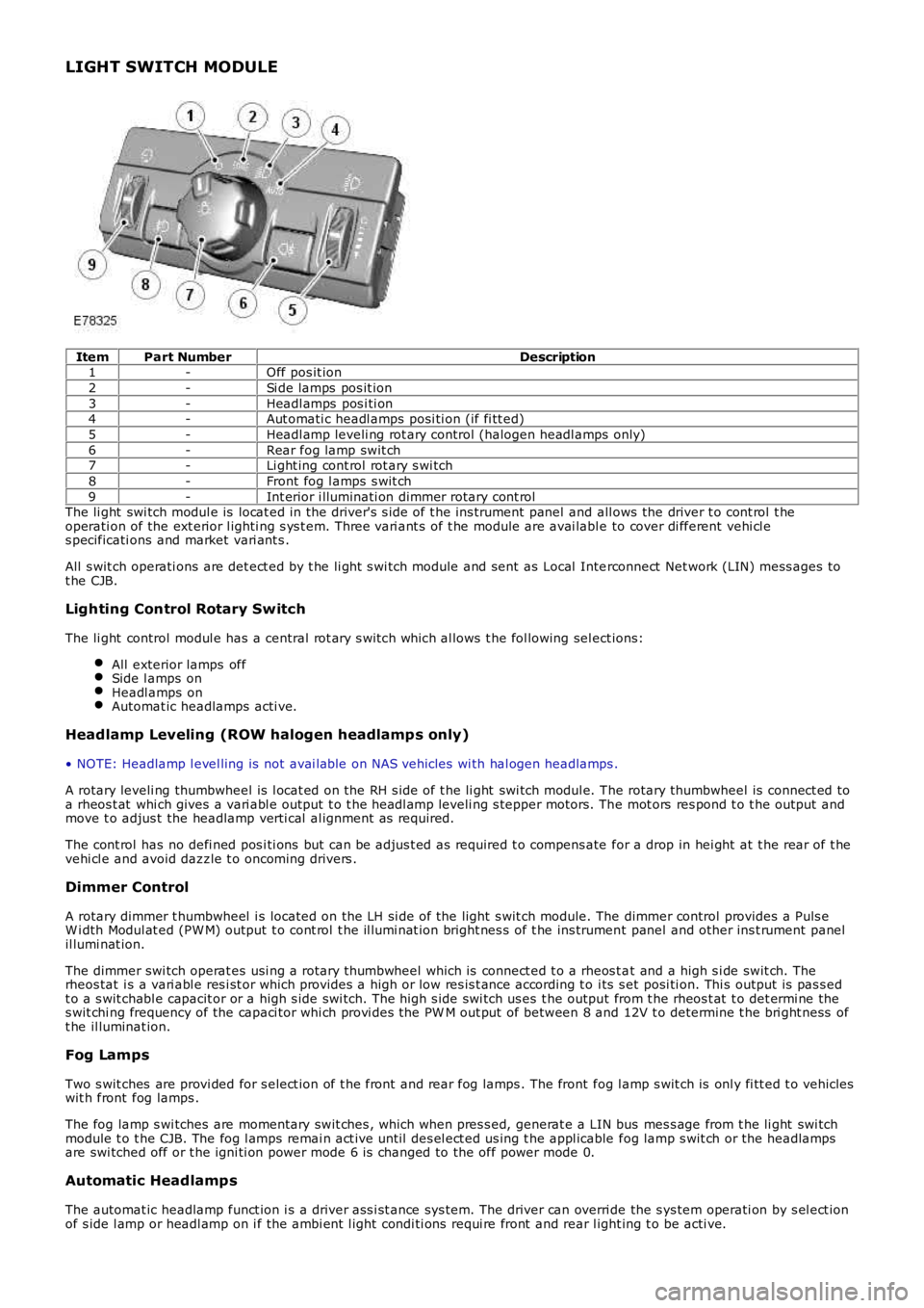
LIGHT SWITCH MODULE
ItemPart NumberDescription1-Off pos it ion
2-Si de lamps pos it ion
3-Headl amps pos i ti on4-Aut omati c headl amps posi ti on (if fi tt ed)
5-Headl amp leveli ng rot ary control (halogen headl amps only)
6-Rear fog lamp swit ch7-Li ght ing cont rol rot ary s wi tch
8-Front fog l amps s wit ch
9-Int erior i lluminati on dimmer rotary cont rolThe li ght swi tch modul e is locat ed in the driver's s ide of t he ins trument panel and all ows the driver t o cont rol t heoperati on of the ext erior l ighti ng s ys t em. Three vari ant s of t he module are avai lable to cover di fferent vehi cl es pecificati ons and market vari ant s .
All s wit ch operati ons are det ect ed by t he li ght s wi tch module and sent as Local Interconnect Net work (LIN) mess ages tot he CJB.
Lighting Control Rotary Switch
The li ght control modul e has a central rot ary s wit ch which al lows t he fol lowing sel ect ions:
All exterior lamps offSide l amps onHeadl amps onAutomat ic headlamps acti ve.
Headlamp Leveling (ROW halogen headlamp s only)
• NOTE: Headlamp l evel ling is not avai lable on NAS vehicles wi th hal ogen headlamps .
A rotary leveli ng thumbwheel is l ocat ed on the RH s ide of t he li ght swi tch modul e. The rotary thumbwheel is connect ed toa rheos t at whi ch gives a vari abl e output t o t he headl amp leveli ng s tepper motors. The mot ors res pond t o t he output andmove t o adjus t the headlamp verti cal al ignment as required.
The cont rol has no defi ned pos i ti ons but can be adjus t ed as required t o compens ate for a drop in hei ght at t he rear of t hevehi cl e and avoid dazzle t o oncoming drivers .
Dimmer Control
A rotary dimmer t humbwheel i s located on the LH si de of the light s wit ch module. The dimmer control provides a Puls eW i dth Modul at ed (PW M) output t o cont rol t he il lumi nat ion bright nes s of t he ins trument panel and other ins t rument panelil lumi nat ion.
The dimmer swi tch operat es usi ng a rotary thumbwheel which is connect ed t o a rheos t at and a high s i de swit ch. Therheos tat i s a vari abl e res i st or which provides a high or low res is t ance according t o i ts s et posi ti on. Thi s output is pas s edt o a s wit chabl e capacit or or a high s ide swi tch. The high s ide swi tch us es t he output from t he rheos t at t o det ermi ne thes wit chi ng frequency of the capaci tor whi ch provi des the PW M out put of between 8 and 12V t o determine t he bri ght ness oft he il luminat ion.
Fog Lamps
Two s wit ches are provi ded for s elect ion of t he front and rear fog lamps . The front fog l amp s wit ch is onl y fi tt ed t o vehicleswit h front fog lamps .
The fog lamp s wi tches are momentary swit ches , which when pres s ed, generat e a LIN bus mes s age from t he li ght swi tchmodule t o t he CJB. The fog l amps remai n act ive unt il des el ect ed us ing t he appl icable fog lamp s wit ch or the headlampsare swi tched off or t he igni ti on power mode 6 is changed to the off power mode 0.
Automatic Headlamp s
The automat ic headlamp funct ion i s a driver ass i st ance sys tem. The driver can override the s ys tem operati on by s el ect ionof s ide l amp or headl amp on i f the ambi ent l ight condi ti ons requi re front and rear light ing t o be acti ve.
Page 1926 of 3229
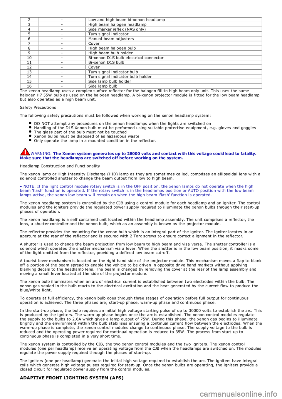
2-Low and hi gh beam bi-xenon headlamp
3-Hi gh beam halogen headl amp
4-Si de marker reflex (NAS only)5-Turn s ignal i ndi cat or
6-Manual beam adjus ters
7-Cover8-Hi gh beam halogen bulb
9-Hi gh beam bulb hol der
10-Bi -xenon D1S bulb el ect ri cal connector11-Bi -xenon D1S bulb
12-Cover
13-Turn s ignal i ndi cat or bul b14-Turn s ignal i ndi cat or bul b holder
15-Si de lamp bul b holder
16-Si de lamp bul bThe xenon headlamp uses a compl ex s urface reflect or for the hal ogen fil l-in hi gh beam only uni t. This us es t he s amehalogen H7 55W bul b as us ed on t he halogen headl amp. A bi-xenon projector module i s fit ted for the l ow beam headlampbut als o operates as a high beam uni t.
Safet y Precaut ions
The fol lowing safety precauti ons mus t be fol lowed when worki ng on t he xenon headlamp sys tem:
DO NOT att empt any procedures on t he xenon headlamps when t he li ghts are s wit ched onHandl ing of t he D1S Xenon bulb mus t be performed usi ng s uit abl e prot ect ive equipment, e.g. gloves and gogglesThe glas s part of t he bulb mus t not be t ouchedXenon bul bs mus t be dis posed of as hazardous was teOnly operat e t he lamp in a mounted condit ion i n t he reflect or.
W ARNING: T he Xenon system generates up to 28000 volts and contact w ith this voltage could lead to fatality.Make sure that the headlamps are sw itched off before w orking on the system.
Headl amp Cons truct ion and Funct ionali ty
The xenon lamp or Hi gh Int ens i ty Di s charge (HID) lamp as they are s ometi mes cal led, compris es an el li ps oidal lens wi th as olenoi d control led s hutt er to change t he beam output from low to hi gh beam.
• NOTE: If the l ight cont rol module rot ary s wit ch is in t he OFF pos it ion, the xenon lamps do not operat e when t he highbeam 'flas h' functi on is operat ed. If t he rot ary s wi tch i s in the headlamps pos it ion or AUTO pos it ion wi th the low beamlamps act ive, the xenon low beam wi ll remai n on when t he high beam 'flas h' funct ion i s operated.
The xenon headlamp sys t em i s cont roll ed by t he CJB usi ng a control modul e for each headl amp and an i gni ter. The cont rolmodules and t he ignit ers provide t he regulat ed power s upply requi red t o i ll uminate the xenon bulbs t hrough t hei r st art -upphas es of operat ion.
The xenon headlamp is a sel f cont ai ned unit located wit hi n t he headl amp as sembl y. The uni t compris es a refl ect or, t helens , a s hutt er controll er and t he xenon bul b, which as an as s embly i s known as the projector module.
The reflector provides t he mounti ng for t he xenon bul b which i s an i ntegral part of t he ignit er. The i gni ter l ocat es in anapert ure at t he rear of the refl ect or and is s ecured wi th 2 Torx s crews t o ens ure correct al ignment in the refl ect or.
A s hutt er is us ed t o change t he beam projecti on from l ow beam t o hi gh beam and vis a vers a. The s hut t er controller i s as olenoi d whi ch operat es t he s hut ter mechani s m vi a a l ever. W hen t he shut ter i s in the l ow beam pos it ion, it mas ks s omeof the light emi tt ed from the refl ect or, providi ng a defi ned low beam cut -off.
A t ouri st l ever mechani s m i s located on the right hand s ide of t he project or modul e. Thi s mechanis m moves a flap t o blankoff a porti on of the beam s pread to enabl e the vehicl e to be dri ven in opposi te dri ve hand markets wit hout applyingblanking decal s t o t he headlamp lens . The beam is changed by removing the cover at the rear of t he lamp ass embly andmoving a small lever locat ed at t he s ide of t he project or modul e.
The xenon bul b il lumi nat es when an arc of el ect ri cal current is es tabli s hed bet ween t wo electrodes wit hi n t he bulb. Thexenon gas s ealed i n t he bulb react s t o t he elect rical excit at ion and the heat generated by t he current flow to produce theblue/whi te li ght .
To operat e at ful l effi ci ency, the xenon bulb goes t hrough t hree s t ages of operat ion before ful l out put for cont inuousoperati on is achieved. The three phas es are; s t art -up phas e, warm-up phas e and continuous phas e.
In the st art -up phas e, the bul b requires an ini ti al hi gh vol tage s t art ing puls e of up t o 30000 volt s to est ablis h the arc. Thisis produced by t he i gni ters. The warm-up phas e begins once t he arc i s est abli shed. The xenon control modul es regulat et he supply to the bulbs t o 2.6A which gi ves a lamp out put of 75W . During t his phas e, the xenon gas begi ns to il luminat ebri ght ly and the environment wi thi n t he bul b s t abi lis es ens uring a cont inual current fl ow bet ween the el ect rodes. W hen thewarm-up phas e is compl et e, the xenon control modul es change t o cont inuous phas e. The s uppl y vol tage t o t he bulb i sreduced and the operat ing power requi red for conti nual operat ion i s reduced to 35W . The proces s from s tart-up t ocont inuous phas e i s complet ed in a very s hort t ime.
The xenon sys tem is cont roll ed by t he CJB, t he two xenon control modul es and the two ignit ers . The xenon controlmodules (one per headlamp) receive an operati ng vol tage from the CJB when the headlamps are s wit ched on. The modulesregulat e t he power s upply requi red t hrough t he phas es of s tart-up.
The ignit ers (one per headl amp) generat e t he ini ti al hi gh vol tage requi red t o es t ablis h t he arc. The ignit ers have i ntegralcoi ls whi ch generate hi gh vol tage pul ses requi red for s tart -up. Once t he xenon bul bs are operat ing, the ignit ers provi de aclos ed ci rcuit for regulat ed power s upply from the control modul es.
ADAPTIVE FRONT LIGHTING SYSTEM (AFS)
Page 1927 of 3229
The s ys t em operat es by t he AFS cont rol module recei vi ng inputs from t he engine cont rol module for engine runni ng s ignal ,t he ABS module for st eeri ng angl e and vehi cle s peed and a reverse gear i nput from the trans mi ss i on.
The AFS cont rol module proces s es thes e s ignals and provi des an output t o the headlamp leveling motors to adjus t theheadl amp hori zont al ai m according t o vehicle speed and s teering angle.
• NOTE: In market s wit h Dayt ime Running Lamps (DRL), t he AFS s yst em will not operate when the DRL are act ive.
The AFS cont rol module is connect ed on the hi gh s peed CAN bus to receive i nformat ion from other vehicle s ys tems . Thecont rol module is connect ed to the AFS power module on a dedi cat ed Local Interconnect Net work (LIN) bus . The AFScont rol module cal culat es, us ing input dat a from other s ys t ems , the requi red pos it ion of t he hori zont al adjus t ment of t heproject or modul es. The pos it ion i nformat ion is t hen output on t he LIN bus to t he AFS power module l ocat ed on eachheadl amp as sembl y. Thi s module t hen outputs the appropriate s ignal s t o power the AFS s t epper mot ors i n t he headl ampt o the appropriat e posi ti on.
The hori zont al pos it ion of t he project or modul es is dependant on a number of input vari abl es . The pos it ion i s determinedby vehi cle s peed and s teeri ng angl e. W hen reverse gear i s elected, the projector modules are moved t o t he st rai ght aheadposi ti on t o avoi d glare t o other road us ers .
The angl es of each projector module di ffer to gi ve the correct spread of light , for example, when turning l eft , the l eft handproject or modul e wi ll have a great er s wi vel ling angl e than t he right hand projector module.
In the event of a fai lure of the AFS sys tem, a warning indicator in the ins trument cl us t er flas hes t o warn the driver. TheAFS warni ng indicator i lluminates when t he i gni ti on s wit ch is i n power mode 6 and will flas h cont inuousl y unti l the faul t isrect ifi ed.
Illumi nati on of the AFS warning i ndi cat or does not neces s aril y mean t hat there is a fault wit h the AFS sys tem. The faultmay be caus ed by a fai lure of anot her sys tem s uch as st eeri ng angl e s ens or or the vehicle s peed s i gnal mi ss i ng,preventi ng the AFS s ys tem operati ng correctl y.
HEADLAMP LEVELING
Headl amp l evel ing provides for the adjus t ment of the vert ical aim of the headlamps to minimi ze glare to other road us erswhen t he vehi cl e att it ude changes due t o vehi cle l oadi ng.
Two t ypes of headlamp l evel ing are avai lable dependant on the t ype of headlamps fit ted to the vehicle:
Manual headlamp l evel ing - Hal ogen headlamps only (ROW vehicles only)Automat ic headlamp level ing - Xenon headlamps only.
Manual Headlamp Leveling - ROW Halogen Headlamps Only
Manual headlamp l evel li ng is only avai lable on RO W vehicles wit h halogen headl amps .
• NOTE: Headlamp l evel ling is not avai lable on NAS vehicles wi th hal ogen headlamps .
The manual s ys tem compris es t he fol lowing components :
Two headlamp l evel ling motorsHeadl amp l evel ing rheos tat rotary cont rol .
W hen t he i gni ti on is i n i gni ti on power mode 6, power i s s uppli ed t o t he li ght control modul e via t he i gni ti on rel ay in t heBJB and a fuse in t he CJB. Power i s als o s uppl ied vi a the ignit ion relay i n the BJB to t he headlamp l evel ing mot or in eachheadl amp as sembl y.
Movement of t he leveli ng rot ary control produces a variable volt age output, whi ch is s ens ed by the motors. The mot orsreact to the suppli ed vol tage and move the headlamp t o t he reques ted pos it ion whi ch rel at es t o t he suppli ed volt age fromt he leveling rotary cont rol . The headlamps can onl y be lowered from t heir unladen posi ti on t o compens ate for changes invehi cl e at ti tude due t o l oading.
The manual headlamp level ing rotary cont rol has no defi ned pos i ti ons whi ch rel at e t o t he vehi cle l oadi ng. The approximat erot ary t humbwheel control pos it ion for a given l oadi ng is s hown i n t he fol lowing t able:
R otary Control RotationVehicle Load
0Driver only or Driver and front s eat pass enger1/4Driver and pass engers i n all s eats
½Maxi mum gross vehicle weight
FullMaxi mum rear axl e load
Automatic Headlamp Leveling - Xenon Headlamps Only
Automat ic headlamp level ing i s only avail abl e on vehicles wi th xenon headlamps . The sys tem is not a Dynami c headl amplevell ing s yst em and changes in vehicle inclinat ion due t o pos it ive and negat ive accelerat ion are not compens ated.
Automat ic headlamp level ing provi des for t he st ati c, periodic adjus t ment of the vertical aim of the headlamps t o mi nimi s eglare to other road us ers when the vehicle at t it ude changes due to loading.
Automat ic headlamp level ing i s cont rol led by a headlamp leveli ng modul e whi ch is l ocat ed on the bul khead, adjacent t ot he ins trument panel on t he pas s enger s ide 'A' pill ar.
• NOTE: On vehicles wit h the AFS sys tem, the headlamp l evel ing s oft ware is i ncorporated i nto the AFS control modul e andt he modul e i s known as the AFS control modul e.
The headl amp l eveli ng s ys t em compri s es the foll owing component s and informat ion from other vehi cl e s yst ems :
Front and rear vehicle height s ensorsTwo headlamp l evel ing, verti cal adjus t ment motors