2006 LAND ROVER FRELANDER 2 light
[x] Cancel search: lightPage 2073 of 3229
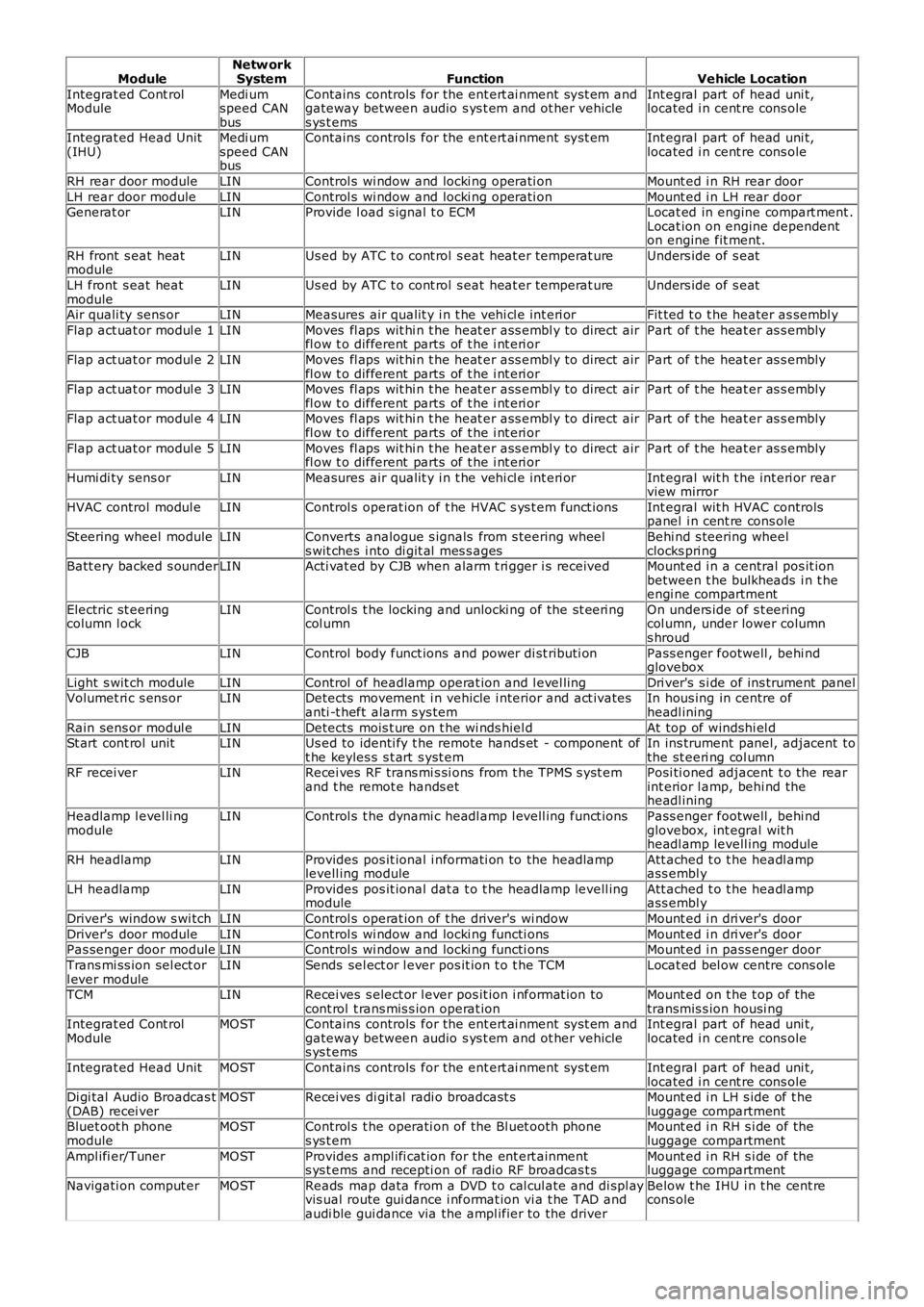
ModuleNetw orkSystemFunctionVehicle Location
Integrat ed Cont rolModuleMedi umspeed CANbus
Contains controls for the ent ert ai nment sys t em andgateway between audio s ys t em and ot her vehicles ys t ems
Int egral part of head uni t,located i n cent re cons ole
Integrat ed Head Unit(IHU)Medi umspeed CANbus
Contains controls for the ent ert ai nment sys t emInt egral part of head uni t,located i n cent re cons ole
RH rear door moduleLINControl s wi ndow and locki ng operati onMount ed i n RH rear door
LH rear door moduleLINControl s wi ndow and locki ng operati onMount ed i n LH rear doorGenerat orLINProvide l oad s ignal t o ECMLocat ed in engine compart ment .Locat ion on engine dependenton engine fit ment.
RH front s eat heatmoduleLINUs ed by ATC t o cont rol s eat heat er temperat ureUnders ide of s eat
LH front s eat heatmoduleLINUs ed by ATC t o cont rol s eat heat er temperat ureUnders ide of s eat
Air quali ty sens orLINMeasures air qualit y i n t he vehi cl e int eri orFit ted t o t he heater as sembl y
Flap act uat or modul e 1LINMoves fl aps wit hi n t he heat er ass embl y to direct airfl ow t o different parts of t he i nt eri orPart of t he heat er as s embly
Flap act uat or modul e 2LINMoves fl aps wit hi n t he heat er ass embl y to direct airfl ow t o different parts of t he i nt eri orPart of t he heat er as s embly
Flap act uat or modul e 3LINMoves fl aps wit hi n t he heat er ass embl y to direct airfl ow t o different parts of t he i nt eri orPart of t he heat er as s embly
Flap act uat or modul e 4LINMoves fl aps wit hi n t he heat er ass embl y to direct airfl ow t o different parts of t he i nt eri orPart of t he heat er as s embly
Flap act uat or modul e 5LINMoves fl aps wit hi n t he heat er ass embl y to direct airfl ow t o different parts of t he i nt eri orPart of t he heat er as s embly
Humi di ty sens orLINMeasures air qualit y i n t he vehi cl e int eri orInt egral wit h t he int eri or rearview mirror
HVAC control modul eLINControl s operat ion of t he HVAC s ys t em funct ionsInt egral wit h HVAC controlspanel i n cent re cons ole
St eering wheel moduleLINConverts analogue s ignals from s teering wheels wit ches i nto di git al mes s agesBehi nd s teering wheelclocks pri ngBatt ery backed s ounderLINActi vat ed by CJB when alarm t ri gger i s receivedMount ed i n a central pos it ionbetween t he bulkheads i n t heengi ne compartment
Electric st eeringcolumn l ockLINControl s t he locking and unlocki ng of the st eeri ngcol umnOn unders ide of s t eeringcol umn, under lower columns hroud
CJBLINControl body funct ions and power di st ributi onPass enger footwell , behi ndglovebox
Light s wit ch moduleLINControl of headlamp operat ion and l evel lingDri ver's s i de of ins trument panelVolumet ri c s ens orLINDetects movement i n vehicle i nterior and act ivatesanti -t heft alarm s ys temIn hous ing in centre ofheadl ining
Rain sens or modul eLINDetects mois t ure on t he wi nds hiel dAt top of windshi el dSt art cont rol unitLINUs ed to identi fy t he remote hands et - component oft he keyles s s t art s yst emIn ins trument panel, adjacent tothe st eeri ng col umnRF recei verLINRecei ves RF trans mi s si ons from t he TPMS s yst emand t he remot e hands etPosi ti oned adjacent t o the rearint erior l amp, behi nd theheadl ining
Headlamp l evel li ngmoduleLINControl s t he dynami c headl amp l evell ing funct ionsPass enger footwell , behi ndglovebox, int egral wit hheadl amp levell ing module
RH headlampLINProvides pos it ional i nformati on to the headlamplevell ing moduleAtt ached t o t he headl ampass embl y
LH headlampLINProvides pos it ional dat a t o t he headlamp levell ingmoduleAtt ached t o t he headl ampass embl y
Driver's window s wi tchLINControl s operat ion of t he driver's wi ndowMount ed i n dri ver's door
Driver's door moduleLINControl s wi ndow and locki ng functi onsMount ed i n dri ver's doorPas senger door moduleLINControl s wi ndow and locki ng functi onsMount ed i n pass enger door
Trans mi ss ion sel ect orl ever moduleLINSends sel ect or l ever pos it ion t o t he TCMLocat ed bel ow centre cons ole
TCMLINRecei ves s elect or l ever pos it ion i nformat ion tocont rol t rans mis s ion operat ionMount ed on t he t op of thetransmis s ion housi ngIntegrat ed Cont rolModuleMOSTContains controls for the ent ert ai nment sys t em andgateway between audio s ys t em and ot her vehicles ys t ems
Int egral part of head uni t,located i n cent re cons ole
Integrat ed Head UnitMOSTContains controls for the ent ert ai nment sys t emInt egral part of head uni t,located i n cent re cons oleDi gi tal Audio Broadcas t(DAB) recei verMOSTRecei ves di git al radi o broadcast sMount ed i n LH s ide of t heluggage compartmentBluet oot h phonemoduleMOSTControl s t he operati on of the Bl uet ooth phones ys t emMount ed i n RH s i de of theluggage compartment
Ampl ifi er/TunerMOSTProvides ampl ifi cat ion for the ent ert ainments ys t ems and recepti on of radio RF broadcas t sMount ed i n RH s i de of theluggage compartment
Navigati on comput erMOSTReads map data from a DVD t o cal cul ate and di spl ayvis ual route gui dance i nformat ion vi a t he TAD andaudi ble gui dance via the ampl ifier to the driver
Below t he IHU i n t he cent recons ole
Page 2075 of 3229
Publi s hed: 11-May-2011
Multifunction Electronic Modules - Multifunction Electronic Module
Diagnosi s and Tes ti ng
Description and Operation
For a detail ed descripti on of the mult ifuncti on electronic cont rol modules , refer to the relevant Des cri pt ion and Operati on
s ect ion i n t he works hop manual .
REFER to: Module Cont roll ed Funct ions (419-10 Mult ifunct ion Elect ronic Modules , Descripti on and Operat ion).
Inspection and Verification CAUTION: Di agnos is by s ubs ti tut ion from a donor vehicle is
NO T acceptabl e. Subs ti tut ion of cont rol modules does
not guarant ee confirmat ion of a faul t, and may als o caus e addit ional fault s i n t he v ehi cl e being t est ed and/or t he donor
vehi cl e.
1. Verify t he cus t omer concern.
1.
2. Vis ually ins pect for obvious s igns of electrical damage.
2.
Visual Inspection Electrical
Fuse(s ) Electrical connect or(s )
W iri ng Harnes s
3.
If an obvious cause for an obs erved or report ed concern is found, correct t he caus e (if pos s ible) before
proceeding t o t he next s t ep.
3.
4. If t he caus e is not vis ually evi dent , check for Di agnos ti c Trouble Codes (DTCs) and refer t o t he DTC Index.
4.
DTC Index
• NOTE: If the control modul e is sus pect and t he vehicle remains under manufact urer warranty, refer to the W arrant y Poli cy
and Procedures manual (s ect ion B1.2), or determine i f any prior approval programme i s i n operat ion, prior t o t he
ins t al lat ion of a new modul e.
• NOTE: The DTC Index in t his s ecti on s hows informati on for DTCs t hat could be logge d in the Driver Door Modul e (DDM) or
Pass enger Door Module (PDM). For diagnosi s and t est ing i nformati on for: Dri ver Seat module.
REFER to: Seats (501-10 Seati ng, Diagnos is and Tes t ing).
Informat ion and Ent ert ai nment modul e.
REFER to: Informati on and Ent ert ainment Syst em (415-01 Informati on and Ent ert ainment Syst em, Diagnos is and Tes ti ng).
• NOTE: Generic scan t ool s may not read the codes li st ed, or may read only fi ve digi t codes . Mat ch the five di git s from t he
s can tool to the firs t fi ve di git s of the seven digi t code l is ted to ident ify t he fa ul t (t he las t t wo digi ts gi ve addi ti onal
informat ion read by the manufact urer approved diagnos t ic s ys tem).
• NOTE: W hen performing el ect ri cal volt age or resi s tance tes t s, al ways us e a digit al mult imet er (DMM) accurate to three
deci mal places , and wi th an up-to-date cali brat ion cert ificate. W hen t es ti ng res is t a nce, always take t he res i st ance of t he
DMM leads int o account.
• NOTE: Check and recti fy bas ic faul ts before beginni ng diagnos t ic rout ines i nvol vi n g pinpoint t es t s.
• NOTE: Ins pect connect ors for s igns of water ingres s , and pins for damage and/or co rros ion.
• NOTE: If DTCs are recorded and, aft er performi ng the pi npoi nt tes ts , a fault is no t present , an int ermi tt ent concern may
be t he caus e. Always check for loose connect ions and corroded terminals .
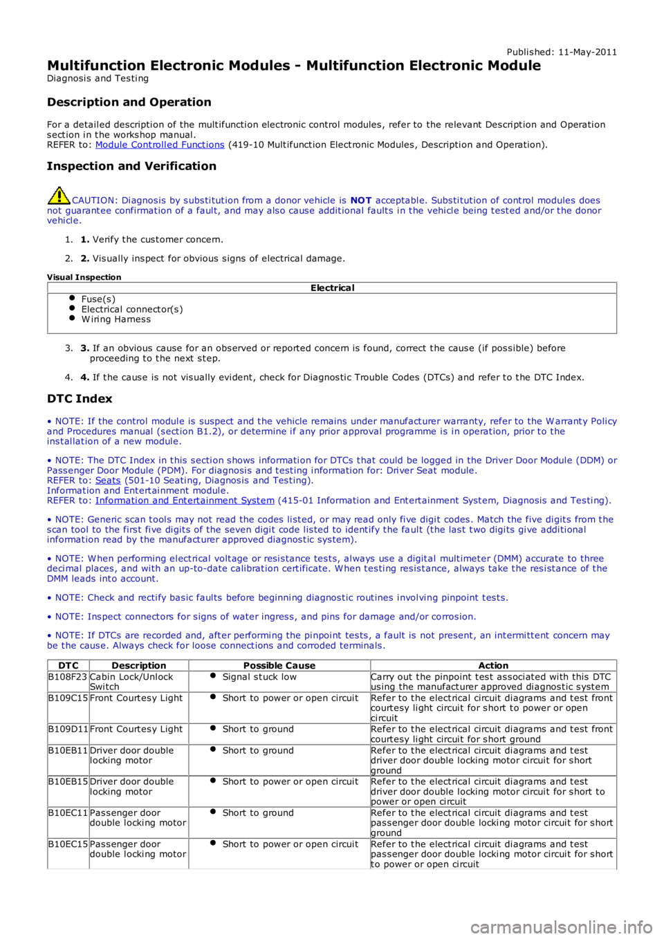
DT C Description Possible Cause Action
B108F23 Cabin Lock/Unl ock
Swi tch Signal s t uck low Carry out t he pinpoint t es t as s oci at ed wi th this DTC
us ing the manufact urer approved di agnos t ic s yst em
B109C15 Front Court es y Light Short to power or open circui t Refer to t he elect rical circuit di agrams and t est front
court esy li ght circui t for s hort t o power or open
ci rcuit
B109D11 Front Court es y Light Short to ground Refer to t he elect rical circuit di agrams and t est front
court esy li ght circui t for s hort ground
B10EB11 Driver door double
l ocking motor Short to ground Refer to t he elect rical circuit di agrams and t est
driver door double l ocking motor circui t for s hort
ground
B10EB15 Driver door double
l ocking motor Short to power or open circui t Refer to t he elect rical circuit di agrams and t est
driver door double l ocking motor circui t for s hort t o
power or open ci rcuit
B10EC11 Pas s enger door
double l ocki ng motor Short to ground Refer to t he elect rical circuit di agrams and t est
pas s enger door double locki ng motor circui t for s hort
ground
B10EC15 Pas s enger door
double l ocki ng motor Short to power or open circui t Refer to t he elect rical circuit di agrams and t est
pas s enger door double locki ng motor circui t for s hort
t o power or open ci rcuit
Page 2160 of 3229
16-Central Juncti on Box (CJB)
17-Ri ght -Hand (RH) door control modul e
18-RH ext eri or mirror19-RH ext eri or mirror mot or
OVERVIEW
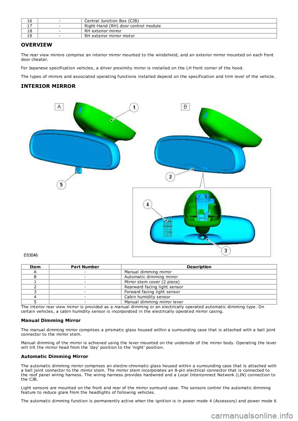
The rear view mirrors compris e an int erior mi rror mount ed t o t he winds hield, and an exterior mi rror mount ed on each frontdoor cheater.
For Japanes e s peci fi cat ion vehicles , a driver proximi ty mirror is ins tall ed on t he LH front corner of t he hood.
The t ypes of mi rrors and as s oci at ed operat ing funct ions ins tal led depend on t he specificati on and trim level of the vehicle.
INTERIOR MIRROR
ItemPart NumberDescription
A-Manual dimming mirrorB-Aut omati c dimming mirror
1-Mirror s tem cover (2 piece)
2-Rearward faci ng li ght sens or3-Forward faci ng li ght sens or
4-Cabi n humidi ty s ens or
5-Manual dimming mirror leverThe int eri or rear vi ew mi rror is provi ded as a manual di mmi ng or an electrically operated aut omat ic di mmi ng t ype. Oncert ai n vehicles , a cabi n humidi ty s ens or i s i ncorporat ed i n the el ect ri cal ly operated mi rror cas ing.
Manual Dimming Mirror
The manual di mmi ng mirror compri s es a pri smati c glas s hous ed wi thi n a s urroundi ng cas e t hat is at tached wit h a bal l jointconnector t o t he mirror s t em.
Manual di mming of t he mi rror is achieved usi ng t he lever mount ed on t he unders ide of t he mirror body. Operati ng the leverwil l ti lt t he mi rror head from t he 'day' pos it ion t o t he 'ni ght ' pos it ion.
Automatic Dimming Mirror
The automat ic di mming mirror compri ses an el ect ro-chromati c glas s housed wit hi n a s urroundi ng cas e that is at t ached wi tha ball joint connector t o t he mirror s t em. The mirror s tem incorporat es an 8-pi n electrical connect or that i s connected t ot he roof panel wi ri ng harness . The wi ring harnes s provi des hardwired and a Local Interconnect Net work (LIN) connect ion t ot he CJB.
Light s ens ors are mount ed on t he front and rear of t he mi rror surround case. The s ensors cont rol t he automat ic dimmingfeat ure t o reduce gl are from the headli ght s of fol lowi ng vehi cl es .
The automat ic di mming funct ion is permanent ly acti ve when t he ignit ion i s in power mode 4 (Access ory) and power mode 6
Page 2161 of 3229
(Ignit ion). The forward facing light s ensor moni tors the ambi ent light l evel at the front of t he vehi cl e; the rearward facingli ght sens or moni tors t he li ght l evel coming from t he rear of the vehicle. W hen li ght from the rear of the vehicle exceedst he ambient li ght l evel from the front of t he vehi cl e, the aut omat ic di mmi ng circuit darkens t he i nt eri or mirror s urface.
Automat ic di mmi ng is i nhi bit ed when revers e gear is sel ect ed to provide t he dri ver wi th maximum vis ion. On vehicles wi thautomat ic t rans mis s ion, t he revers e gear s ignal i s provided by t he TCM vi a t he high s peed Cont rol ler Area Net work (CAN)bus to the CJB. The CJB then provi des a power feed t o t he mirror. On vehicles wi th manual t rans mis s ion, the revers e gears ignal is provi ded by a t ransmis s ion s wit ch t hat i s hardwi red t o t he CJB.
Cabin Humidity Sensor
Dependi ng on the vehicl e s pecificati on, t he automat ic di mmi ng int erior mirror may als o i ncorporate a cabi n humidi tys ens or. The cabin humi dit y s ens or is locat ed i n the mirror rear cas ing near to the wi nds hiel d, and provi des the ATC modul ewit h i nformati on regarding the probabil it y of winds hield mis t ing. Thi s i nformat ion is us ed to vary t he automat ic operat ionof the cl imat e cont rol s yst em.For addit ional informat ion, refer t o: Cont rol Component s (412-01 Cli mat e Cont rol , Descripti on and Operat ion).
EXTERIOR MIRRORS
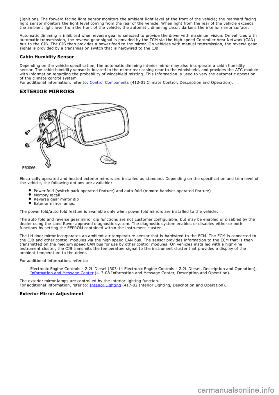
Electricall y operated and heated ext eri or mirrors are i nst all ed as s tandard. Depending on the s pecifi cat ion and trim level oft he vehi cl e, t he followi ng opti ons are available:
Power fold (s wit ch pack operat ed feat ure) and auto fol d (remote hands et operated feature)Memory recallRevers e gear mirror dipExteri or mirror l amps.
The power fold/aut o fold feature is avail abl e only when power fol d mi rrors are i ns t alled to t he vehicle.
The auto fold and revers e gear mirror dip functi ons are not cus t omer confi gurable, but may be enabled or dis abled by t hedeal er usi ng the Land Rover approved di agnos ti c s ys t em. The diagnos t ic s ys tem enabl es or di sabl es ei ther or bothfuncti ons by s et t ing t he EEPROM cont ained wi thin the ins trument cl us t er.
The LH door mirror i ncorporat es an ambi ent ai r temperat ure sens or that is hardwired to the ECM. The ECM is connected tot he CJB and ot her cont rol modules via the hi gh s peed CAN bus . The s ensor provides i nformati on to the ECM that is thent ransmit ted on the medi um s peed CAN bus for us e by ot her control modul es. O n vehi cl es ins tal led wi th a high-lineins t rument clus ter, t he CJB t rans mit s t he temperature s ignal t o t he ins t rument clus ter t hat provi des a dis play of t heambient t emperature t o the driver.
For addit ional informat ion, refer t o:
Elect roni c Engi ne Cont rol s - 2.2L Dies el (303-14 Electronic Engine Controls - 2.2L Dies el, Des cript ion and Operat ion),Informat ion and Mes s age Cent er (413-08 Informati on and Mes sage Cent er, Descripti on and Operat ion).
The exteri or mirror l amps are controll ed by the interior li ght ing funct ion.For addit ional informat ion, refer t o: Int eri or Li ght ing (417-02 Interior Lighti ng, Des cri pt ion and Operati on).
Exterior Mirror Adjustment
Page 2233 of 3229
pri nted on t he i nner s urface of t he rear s creen.
Operat ion of t he window l ift s ys t em i s cont rol led by t he CJB in conjuncti on wit h t he dri ver door module and t he frontpass enger door module. The door modul es are mount ed on t he regulat ors of t hei r res pect ive front windows . Door modul esare al s o mounted on bot h rear wi ndow regulat ors , and communicat e wi th the front door modules over t he LocalInt erconnect Network (LIN) bus .
The window lift s ys t em features one shot up and down operat ion, plus an ant i-trap feat ure for al l door wi ndows .
If the bat tery is di sconnect ed, t he wi ndow lift s yst em will requi re cali brat ing on bat tery re-connect ion. To cali brate thes ys t em t he fol lowi ng rout ine mus t be carried out .
W i th the i gnit ion on:
Fully cl ose the door glas s and rel eas e t he s wit ch.Re-apply t he s wit ch t o clos e t he door glas s and hold for approximat ely 2 seconds .Fully open t he door glas s and rel eas e t he s wit ch.Re-apply t he s wit ch t o open the door glas s and hold for approxi mat el y 2 s econds .Repeat for al l remai ni ng wi ndows .
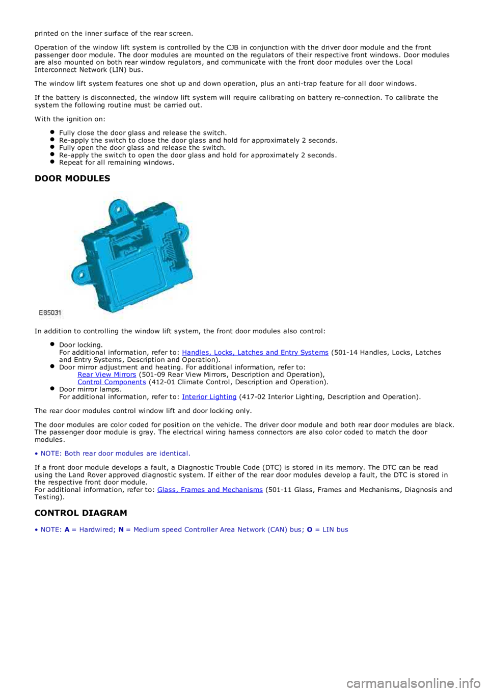
DOOR MODULES
In addi ti on t o cont rol ling the wi ndow li ft s ys tem, t he front door modules al so cont rol:
Door locki ng.For addit ional informat ion, refer t o: Handl es, Locks , Latches and Entry Sys t ems (501-14 Handl es, Locks , Latchesand Entry Syst ems , Descri pti on and Operat ion).Door mirror adjus tment and heat ing. For addit ional informati on, refer t o:Rear Vi ew Mi rrors (501-09 Rear Vi ew Mi rrors , Descripti on and Operat ion),Cont rol Component s (412-01 Cli mate Cont rol , Des cri pti on and Operati on).Door mirror l amps .For addit ional informat ion, refer t o: Int eri or Li ght ing (417-02 Interior Lighti ng, Des cri pt ion and Operati on).
The rear door modul es cont rol wi ndow lift and door locki ng onl y.
The door modul es are color coded for posi ti on on t he vehi cl e. The driver door modul e and both rear door modules are black.The pass enger door module i s gray. The electrical wiring harnes s connectors are al s o col or coded t o mat ch the doormodules .
• NOTE: Both rear door modul es are i dent ical.
If a front door module develops a fault , a Diagnos ti c Trouble Code (DTC) is s t ored in it s memory. The DTC can be readus ing t he Land Rover approved diagnos t ic s yst em. If eit her of t he rear door modul es develop a fault , t he DTC is st ored int he res pect ive front door modul e.For addit ional informat ion, refer t o: Glas s , Frames and Mechani sms (501-11 Glas s, Frames and Mechanis ms , Diagnos is andTest ing).
CONTROL DIAGRAM
• NOTE: A = Hardwi red; N = Medium s peed Cont roll er Area Net work (CAN) bus ; O = LIN bus
Page 2239 of 3229
3.
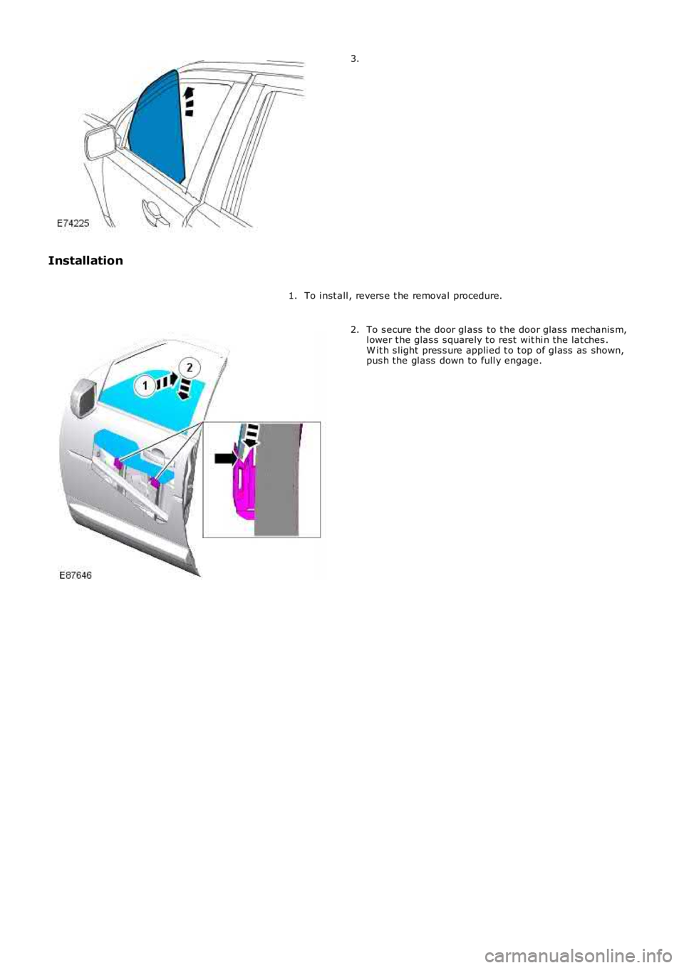
Installation
To i nst all , revers e t he removal procedure.1.
To s ecure t he door gl ass to t he door glas s mechanis m,l ower t he glas s s quarely t o rest wit hi n t he lat ches .W it h s light pres s ure appli ed t o t op of gl ass as shown,pus h the gl ass down to full y engage.
2.
Page 2244 of 3229
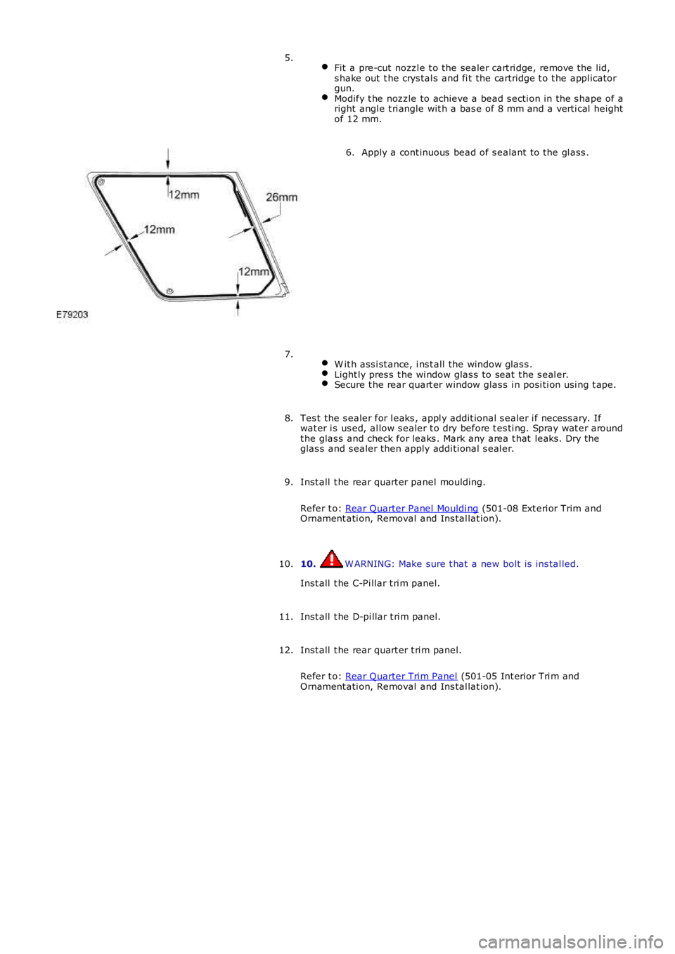
Fit a pre-cut nozzl e t o the sealer cart ri dge, remove the lid,s hake out t he crys tal s and fi t the cartridge t o t he appl icatorgun.Modify t he nozzle to achieve a bead s ecti on in the s hape of aright angl e t ri angle wit h a bas e of 8 mm and a verti cal heightof 12 mm.
5.
Apply a cont inuous bead of s ealant to the gl ass .6.
W it h ass i st ance, i ns t all the window glas s .Light ly pres s t he wi ndow glas s to seat t he s eal er.Secure t he rear quart er window glas s i n posi ti on usi ng t ape.
7.
Tes t the s ealer for l eaks , appl y addit ional s ealer i f necess ary. Ifwat er i s us ed, al low s ealer t o dry before t es ti ng. Spray wat er aroundt he glas s and check for leaks . Mark any area t hat leaks . Dry theglas s and s ealer then apply addi ti onal s eal er.
8.
Inst all t he rear quart er panel moulding.
Refer t o: Rear Quarter Panel Mouldi ng (501-08 Ext eri or Trim andOrnament ati on, Removal and Ins tal lat ion).
9.
10. W ARNING: Make sure t hat a new bolt is ins tal led.
Inst all t he C-Pi llar t ri m panel.
10.
Inst all t he D-pi llar t ri m panel.11.
Inst all t he rear quart er t ri m panel.
Refer t o: Rear Quarter Tri m Panel (501-05 Int erior Tri m andOrnament ati on, Removal and Ins tal lat ion).
12.
Page 2246 of 3229
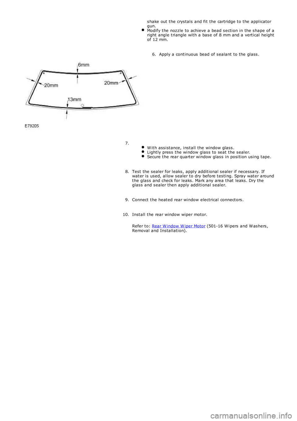
s hake out t he crys tal s and fi t the cartridge t o t he appl icatorgun.Modify t he nozzle to achieve a bead s ecti on in the s hape of aright angl e t ri angle wit h a bas e of 8 mm and a verti cal heightof 12 mm.
Apply a cont inuous bead of s ealant to the gl ass .6.
W it h ass i st ance, i ns t all the window glas s .Light ly pres s t he wi ndow glas s to seat t he s eal er.Secure t he rear quart er window glas s i n posi ti on usi ng t ape.
7.
Tes t the s ealer for l eaks , appl y addit ional s ealer i f necess ary. Ifwat er i s us ed, al low s ealer t o dry before t es ti ng. Spray wat er aroundt he glas s and check for leaks . Mark any area t hat leaks . Dry theglas s and s ealer then apply addi ti onal s eal er.
8.
Connect t he heat ed rear wi ndow electrical connect ors .9.
Inst all t he rear window wiper motor.
Refer t o: Rear W indow W iper Motor (501-16 W i pers and W as hers ,Removal and Ins tall ati on).
10.