2006 LAND ROVER FRELANDER 2 light
[x] Cancel search: lightPage 102 of 3229
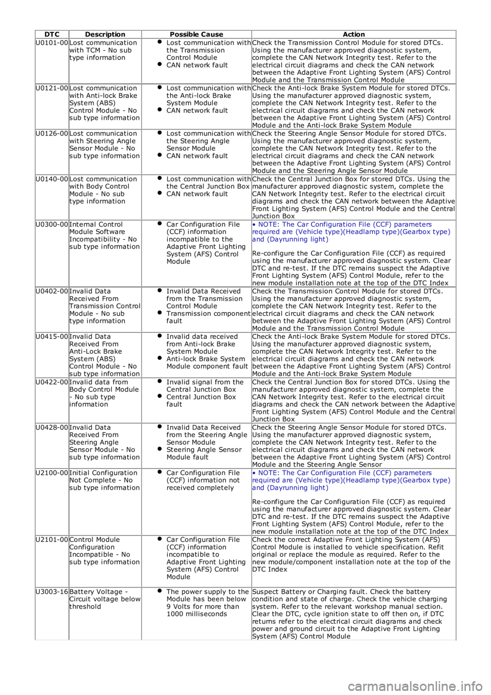
DT CDescriptionPossible CauseAction
U0101-00Lost communicat ionwit h TCM - No s ubt ype i nformati on
Los t communi cat ion wi tht he Trans mis s ionControl Modul eCAN net work fault
Check t he Trans mis s ion Cont rol Module for st ored DTCs .Us ing t he manufacturer approved diagnost ic sys tem,compl ete the CAN Net work Int egrit y t est . Refer t o theelectrical ci rcuit diagrams and check t he CAN networkbet ween t he Adapt ive Front Li ght ing Sys tem (AFS) ControlModul e and t he Trans mis s ion Cont rol Modul eU0121-00Lost communicat ionwit h Ant i-lock BrakeSyst em (ABS)Control Module - Nos ub type i nformati on
Los t communi cat ion wi tht he Anti -l ock BrakeSys tem Modul eCAN net work fault
Check t he Anti -l ock Brake Sys t em Module for s tored DTCs.Us ing t he manufacturer approved diagnost ic sys tem,compl ete the CAN Net work Int egrit y t est . Refer t o theelectrical ci rcuit diagrams and check t he CAN networkbet ween t he Adapt ive Front Li ght ing Sys tem (AFS) ControlModul e and t he Anti -l ock Brake Sys t em ModuleU0126-00Lost communicat ionwit h St eering Angl eSens or Module - Nos ub type i nformati on
Los t communi cat ion wi tht he Steering AngleSensor ModuleCAN net work fault
Check t he Steering Angle Sens or Modul e for s t ored DTCs .Us ing t he manufacturer approved diagnost ic sys tem,compl ete the CAN Net work Int egrit y t est . Refer t o theelectrical ci rcuit diagrams and check t he CAN networkbet ween t he Adapt ive Front Li ght ing Sys tem (AFS) ControlModul e and t he Steeri ng Angle Sens or Module
U0140-00Lost communicat ionwit h Body ControlModule - No subt ype i nformati on
Los t communi cat ion wi tht he Central Junct ion BoxCAN net work fault
Check t he Central Junct ion Box for s tored DTCs . Us ing themanufacturer approved diagnost ic sys tem, complet e t heCAN Net work Integri ty tes t. Refer t o t he electrical ci rcuitdiagrams and check the CAN network bet ween t he Adapt iveFront Lighti ng Sys t em (AFS) Cont rol Modul e and t he CentralJuncti on Box
U0300-00Int ernal Cont rolModule Soft wareIncompati bili ty - Nos ub type i nformati on
Car Configurat ion Fi le(CCF) i nformati oni ncompati ble t o t heAdapti ve Front Li ghti ngSys tem (AFS) Cont rolModule
• NOTE: The Car Configurat ion Fil e (CCF) parametersrequired are (Vehicle type)(Headl amp t ype)(Gearbox t ype)and (Dayrunning light )
Re-configure the Car Confi gurati on Fil e (CCF) as requi redusi ng t he manufact urer approved diagnost ic s ys tem. Cl earDTC and re-t es t . If t he DTC remains s us pect t he Adapt iveFront Lighti ng Sys t em (AFS) Cont rol Modul e, refer t o t henew module ins tall ati on not e at t he t op of the DTC IndexU0402-00Invali d Dat aRecei ved FromTrans mis s ion Cont rolModule - No subt ype i nformati on
Inval id Dat a Recei vedfrom the Transmis si onControl Modul eTrans mi ss i on componentfaul t
Check t he Trans mis s ion Cont rol Module for st ored DTCs .Us ing t he manufacturer approved diagnost ic sys tem,compl ete the CAN Net work Int egrit y t est . Refer t o theelectrical ci rcuit diagrams and check t he CAN networkbet ween t he Adapt ive Front Li ght ing Sys tem (AFS) ControlModul e and t he Trans mis s ion Cont rol Modul eU0415-00Invali d Dat aRecei ved FromAnti -Lock BrakeSyst em (ABS)Control Module - Nos ub type i nformati on
Inval id dat a receivedfrom Anti -l ock BrakeSys tem Modul eAnt i-lock Brake Syst emModule component fault
Check t he Anti -l ock Brake Sys t em Module for s tored DTCs.Us ing t he manufacturer approved diagnost ic sys tem,compl ete the CAN Net work Int egrit y t est . Refer t o theelectrical ci rcuit diagrams and check t he CAN networkbet ween t he Adapt ive Front Li ght ing Sys tem (AFS) ControlModul e and t he Anti -l ock Brake Sys t em Module
U0422-00Invali d data fromBody Cont rol Module- No s ub t ypeinformat ion
Inval id s i gnal from theCentral Juncti on BoxCentral Juncti on Boxfaul t
Check t he Central Junct ion Box for s tored DTCs . Us ing themanufacturer approved diagnost ic sys tem, complet e t heCAN Net work Integri ty tes t. Refer t o t he electrical ci rcuitdiagrams and check the CAN network bet ween t he Adapt iveFront Lighti ng Sys t em (AFS) Cont rol Modul e and t he CentralJuncti on Box
U0428-00Invali d Dat aRecei ved FromSteering AngleSens or Module - Nos ub type i nformati on
Inval id Dat a Recei vedfrom the St eeri ng Angl eSensor ModuleSt eering Angle Sens orModule fault
Check t he Steering Angle Sens or Modul e for s t ored DTCs .Us ing t he manufacturer approved diagnost ic sys tem,compl ete the CAN Net work Int egrit y t est . Refer t o theelectrical ci rcuit diagrams and check t he CAN networkbet ween t he Adapt ive Front Li ght ing Sys tem (AFS) ControlModul e and t he Steeri ng Angle Sens or
U2100-00Ini ti al Configurat ionNot Complet e - Nos ub type i nformati on
Car Configurat ion Fi le(CCF) i nformati on notreceived complet ely
• NOTE: The Car Configurat ion Fil e (CCF) parametersrequired are (Vehicle type)(Headl amp t ype)(Gearbox t ype)and (Dayrunning light )
Re-configure the Car Confi gurati on Fil e (CCF) as requi redusi ng t he manufact urer approved diagnost ic s ys tem. Cl earDTC and re-t es t . If t he DTC remains s us pect t he Adapt iveFront Lighti ng Sys t em (AFS) Cont rol Modul e, refer t o t henew module ins tall ati on not e at t he t op of the DTC IndexU2101-00Control ModuleConfigurat ionIncompati ble - Nos ub type i nformati on
Car Configurat ion Fi le(CCF) i nformati oni ncompati ble t oAdapti ve Front Li ghti ngSys tem (AFS) Cont rolModule
Check t he correct Adapti ve Front Li ght ing Sys t em (AFS)Cont rol Module is i ns t alled to vehicle s pecificati on. Refitori gi nal or repl ace the modul e as required. Refer to thenew module/component ins tall ati on note at t he t op of theDTC Index
U3003-16Batt ery Vol tage -Circui t vol tage belowt hreshol d
The power s upply to theModule has been below9 Vol ts for more than1000 mi ll is econds
Sus pect Bat t ery or Charging fault . Check t he batt erycondit ion and st ate of charge. Check t he vehicle chargi ngs ys t em. Refer to the relevant workshop manual s ect ion.Clear the DTC, cycl e i gni ti on s tat e to off t hen on, i f DTCret urns refer to the el ect ri cal circui t diagrams and checkpower and ground ci rcuit t o t he Adapt ive Front Light ingSys t em (AFS) Cont rol Modul e
Page 103 of 3229
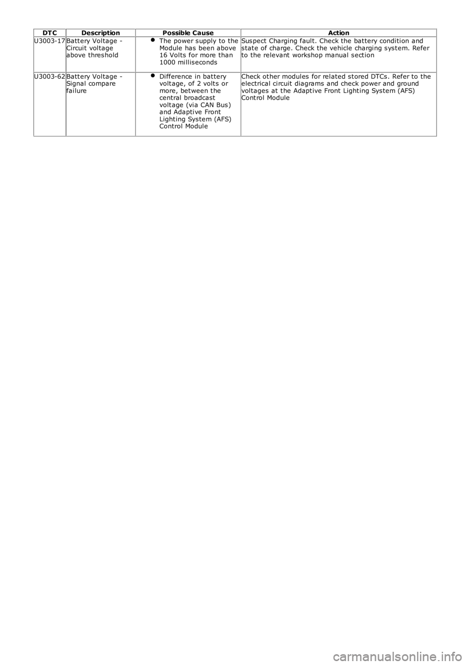
DT CDescriptionPossible CauseAction
U3003-17Batt ery Vol tage -Circui t vol tageabove thres hold
The power s upply to theModule has been above16 Vol ts for more than1000 mi ll is econds
Sus pect Charging faul t. Check the bat tery condi ti on ands tat e of charge. Check the vehicle chargi ng s ys t em. Referto the relevant workshop manual s ect ion
U3003-62Batt ery Vol tage -Signal comparefai lure
Di fference in bat teryvolt age, of 2 volt s ormore, bet ween t hecentral broadcastvolt age (vi a CAN Bus )and Adapti ve FrontLight ing Sys tem (AFS)Control Modul e
Check ot her modul es for rel ated s t ored DTCs . Refer to theelectrical ci rcuit diagrams and check power and groundvol tages at t he Adapt ive Front Light ing Sys tem (AFS)Cont rol Module
Page 113 of 3229

Publi s hed: 03-May-2011
General Information - Diagnostic Trouble Code (DTC) IndexDTC:
Instrument Cluster (IPC)
Des cript ion and Operat ion
• NOTE: If a cont rol module or component i s s uspect and the vehicl e remai ns under manufacturer warrant y, refer t o t heW arranty Pol icy and Procedures manual (s ect ion B1.2), or determine i f any pri or approval program is i n operat ion, beforet he replacement of a component.
• NOTE: Generic scan t ool s may not read the codes li st ed, or may read only 5-digi t codes . Match t he 5 digi ts from t he s cant ool t o t he fi rs t 5 di gi ts of the 7-digit code li s ted t o i dent ify the fault (the last 2 digi ts gi ve ext ra informati on read by themanufacturer-approved di agnos ti c s ys t em).
• NOTE: W hen performing volt age or res is t ance t est s , always use a digi tal mult imeter (DMM) accurat e t o t hree deci malplaces, and wi th an up-t o-date cal ibrat ion cert ificate. W hen tes ti ng res is t ance al ways take t he res is t ance of t he DMMleads i nt o account .
• NOTE: Check and recti fy bas ic faul ts before beginni ng diagnos t ic rout ines i nvol vi ng pinpoint t es t s.
• NOTE: Ins pect connect ors for s igns of water ingres s , and pins for damage and/or corros ion.
• NOTE: If DTCs are recorded and, aft er performi ng the pi npoi nt tes ts , a fault is not present , an int ermi tt ent concern maybe t he caus e. Always check for loose connect ions and corroded terminals .
Des cript ion And Operat ion
For a detail ed descripti on of the ins trument cl us t er sys tem, refer t o t he rel evant Descripti on and Operat ion s ecti on in t heworks hop manual .For addit ional informat ion, refer t o: Ins t rument Clus ter (413-01 Inst rument Cl us t er, Des cript ion and Operat ion).
Instrument cluster control module (IPC )DT CDescriptionPossible CauseAction
B1184-62Steering Column LockOutputSignal compare fai lureCheck st eering lock power from CJB. Check CJB forDTCs and refer to relevant DTC Index.For addi ti onal informat ion, refer t o:Communicati ons Network (418-00 Modul eCommunicati ons Network, Di agnos is and Tes t ing).
B1A14-96RCM W arning LampLight Emit t ing Di ode (LED)fai lureIns t all a new ins trument cl us t er.For addi ti onal informat ion, refer t o: Ins t rumentClus t er (413-01 Inst rument Cl us t er, Removal andIns t allat ion).Refer t o t he new module/component ins tall ati onnote at the t op of the DTC Index
B1A84-41Car Configurat ion Dat aFlas h download checks umerrorIns t all lat est avail abl e l evel of software us ing t hemanufacturer approved di agnos ti c s ys t em
B1A84-81Car Configurat ion Dat aInvali d Car Configurat iondata recei vedCheck/amend Car Configurat ion Fil e us ingmanufacturer approved di agnos ti c s ys t em
C2002-62Odometer TamperedDTC s et when one or mores tored odomet er val ue doesnot match
Clear DTC, cycle ignit ion and re-t est
U0010-87Medium Speed CANCommunicati on BusMult ipl e los s of CAN dat a toother s yst emsCarry out pinpoint tes t s ass ociat ed wit h t his DTCus ing t he manufacturer approved diagnos ti cs yst em
U0010-88Medium Speed CANCommunicati on BusBreak i n connecti on to busCarry out pinpoint tes t s ass ociat ed wit h t his DTCus ing t he manufacturer approved diagnos ti cs yst emU0140-08Lost Communi cat ionW i th Body Cont rolModule
No mes s ages recei ved fromCJB for great er than t imeoutperi od
Carry out pinpoint tes t s ass ociat ed wit h t his DTCus ing t he manufacturer approved diagnos ti cs yst em
U0208-08Lost Communi cat ionW i th "Seat Cont rolModule A"
No mes s ages recei ved fromDSM for greater t hant imeout period
Check DSM for DTCs and refer t o rel evant DTCIndex.For addi ti onal informat ion, refer t o: Seat s (501-10Seati ng, Di agnos is and Tes ti ng).Carry out CAN Net work i nt egri ty t es ts us ing themanufacturer approved di agnos ti c s ys t emU0300-62Int ernal Cont rol ModuleSoft ware Incompat ibi lit yConfigurat ion dat a receivedis di fferent from the s t oreddata
Check correct ins trument cl us t er is i nst all ed
U3000-46Control ModuleEEPROM writ e errorCheck power and ground circui ts to the i nst rumentclus ter, cl ear DTC and re-tes t. If DTC remains ,ins t al l a new i nst rument clus t er.For addi ti onal informat ion, refer t o: Ins t rumentClus t er (413-01 Inst rument Cl us t er, Removal andIns t allat ion).Refer t o t he new module/component ins tall ati onnote at the t op of the DTC Index
Page 151 of 3229
Publi s hed: 04-May-2011
General Information - Diagnostic Trouble Code (DTC) IndexDTC: Trailer
Module (TRM)
Des cript ion and Operat ion
• NOTE: If a cont rol module or component i s s uspect and the vehicl e remai ns under ma nufacturer warrant y, refer t o t he
W arranty Pol icy and Procedures manual (s ect ion B1.2), or determine i f any pri or appr oval program is i n operat ion, before
t he replacement of a component.
• NOTE: Generic scan t ool s may not read the codes li st ed, or may read only 5-digi t c odes . Match t he 5 digi ts from t he s can
t ool t o t he fi rs t 5 di gi ts of the 7-digit code li s ted t o i dent ify the fault (the las t 2 digi ts gi ve ext ra informati on read by the
manufacturer-approved di agnos ti c s ys t em).
• NOTE: W hen performing volt age or res is t ance t est s , always use a digi tal mult imeter (DMM) accurat e t o t hree deci mal
places, and wi th an up-t o-date cal ibrat ion cert ificate. W hen tes ti ng res is t ance al wa ys take t he res is t ance of t he DMM
leads i nt o account .
• NOTE: Check and recti fy bas ic faul ts before beginni ng diagnos t ic rout ines i nvol vi n g pinpoint t es t s.
• NOTE: Ins pect connect ors for s igns of water ingres s , and pins for damage and/or co rros ion.
• NOTE: If DTCs are recorded and, aft er performi ng the pi npoi nt tes ts , a fault is no t present , an int ermi tt ent concern may
be t he caus e. Always check for loose connect ions and corroded terminals .
Des cript ion And Operat ion
For a detail ed descripti on of the trai ler module sys tem, refer t o t he rel evant Des cr ipt ion and Operat ion s ecti on in the
works hop manual . For addit ional informat ion, refer t o: Ext eri or Li ght ing (417-01 Ext erior Light ing, Des cri pti on and
Operat ion).
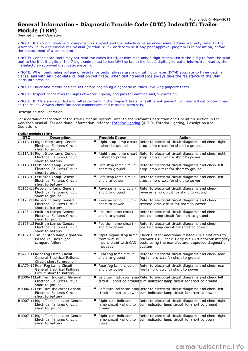
Trailer module (TRM) DT C Description Possible Cause Action
C111A-11 Right Stop Lamp General
Electrical Fai lures Ci rcuit
s hort t o ground Right s top l amp circui t
- s hort t o ground Refer to el ect ri cal circui t diagrams and check ri ght
s t op lamp ci rcuit for short to ground
C111A-12 Right Stop Lamp General
Electrical Fai lures Ci rcuit
s hort t o batt ery Right s top l amp circui t
- s hort t o power Refer to el ect ri cal circui t diagrams and check ri ght
s t op lamp ci rcuit for short to power
C111B-11 Left St op Lamp General
Electrical Fai lures Ci rcuit
s hort t o ground Left s top lamp circui t -
s hort to ground Refer to el ect ri cal circui t diagrams and check left
s t op lamp ci rcuit for short to ground
C111B-12 Left St op Lamp General
Electrical Fai lures Ci rcuit
s hort t o batt ery Left s top lamp circui t -
s hort to power Refer to el ect ri cal circui t diagrams and check left
s t op lamp ci rcuit for short to power
C1120-11 Revers ing l amp General
Electrical Fai lures Ci rcuit
s hort t o ground Reverse lamp ci rcuit -
s hort to ground Refer to el ect ri cal circui t diagrams and check
revers e lamp ci rcuit for short to ground
C1120-12 Revers ing l amp General
Electrical Fai lures Ci rcuit
s hort t o batt ery Reverse lamp ci rcuit -
s hort to power Refer to el ect ri cal circui t diagrams and check
revers e lamp ci rcuit for short to power
C1126-11 Posi ti on Lamps General
Electrical Fai lures Ci rcuit
s hort t o ground Posi ti on lamp ci rcuit -
s hort to ground Refer to el ect ri cal circui t diagrams and check
pos it ion l amp circui t for s hort t o ground
C1126-12 Posi ti on Lamps General
Electrical Fai lures Ci rcuit
s hort t o batt ery Posi ti on lamp ci rcuit -
s hort to power Refer to el ect ri cal circui t diagrams and check
pos it ion l amp circui t for s hort t o power
B1102-62 Trai ler s top l amp Algorit hm
Based Fai lures Si gnal
compare failure Input s ignal st op l amp
from wire is
incons i st ent wit h CAN
mes sage Check CJB for addit ional relat ed DTCs and refer to
relevant DTC Index. Carry out CAN net work integrit y
t es ts us ing the manufact urer approved di agnos t ic
s ys tem
B1A79-11 Rear Fog Lamp Circuit
General Elect rical Fail ures
Circui t s hort to ground Rear fog l amp circuit -
s hort to ground Refer to el ect ri cal circui t diagrams and check rear
fog l amp circuit for s hort to ground
B1A79-12 Rear Fog Lamp Circuit
General Elect rical Fail ures
Circui t s hort to bat t ery Rear fog l amp circuit -
s hort to power Refer to el ect ri cal circui t diagrams and check rear
fog l amp circuit for s hort to power
B1D06-11 Left Turn Indicator General
Electrical Fai lures Ci rcuit
s hort t o ground Left t urn i ndi cat or lamp
circuit - short to ground Refer to el ect ri cal circui t diagrams and check left
t urn indicator l amp circuit for s hort to ground
B1D06-12 Left Turn Indicator General
Electrical Fai lures Ci rcuit
s hort t o batt ery Left t urn i ndi cat or lamp
circuit - short to power Refer to el ect ri cal circui t diagrams and check left
t urn indicator l amp circuit for s hort to power
B1D07-11 Right Turn Indicator General
Electrical Fai lures Ci rcuit
s hort t o ground Right t urn i ndi cat or
lamp ci rcuit - s hort t o
ground Refer to el ect ri cal circui t diagrams and check ri ght
t urn indicator l amp circuit for s hort to ground
B1D07-12 Right Turn Indicator General
Electrical Fai lures Ci rcuit
s hort t o batt ery Right t urn i ndi cat or
lamp ci rcuit - s hort t o
power Refer to el ect ri cal circui t diagrams and check ri ght
t urn indicator l amp circuit for s hort to power
Page 297 of 3229
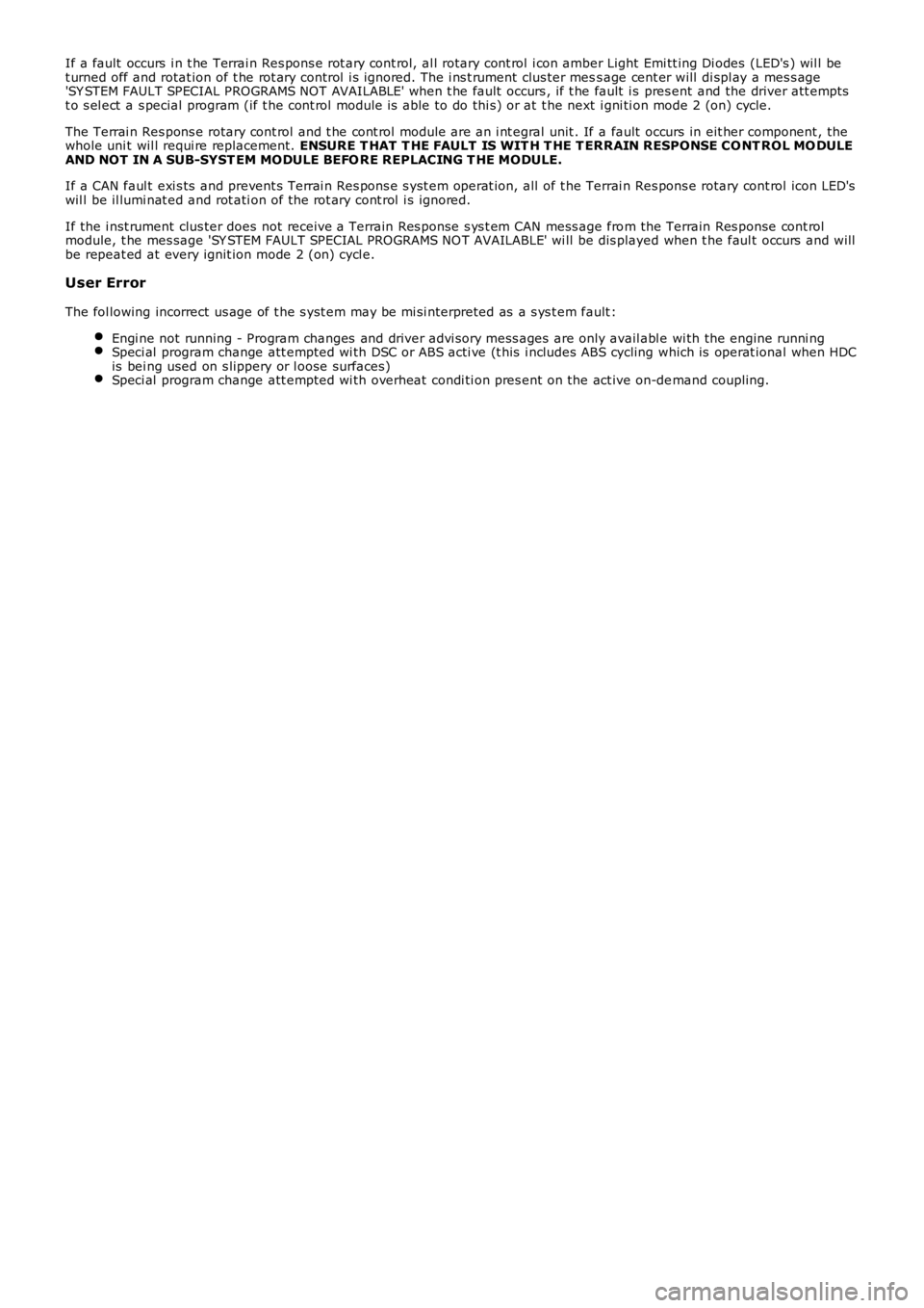
If a fault occurs i n t he Terrai n Res pons e rot ary cont rol, al l rotary cont rol i con amber Light Emi tt ing Di odes (LED's ) wil l bet urned off and rotat ion of t he rot ary control i s ignored. The i ns t rument clus ter mess age cent er will di spl ay a mes s age'SY STEM FAULT SPECIAL PROGRAMS NOT AVAILABLE' when t he fault occurs , if t he fault i s pres ent and the driver att emptst o s el ect a s pecial program (if t he cont rol module is able to do thi s) or at t he next i gni ti on mode 2 (on) cycle.
The Terrai n Res pons e rotary cont rol and t he cont rol module are an i nt egral unit . If a fault occurs in eit her component , thewhole uni t wil l requi re replacement. ENSURE T HAT T HE FAULT IS WIT H T HE T ERRAIN RESPONSE CO NT ROL MO DULEAND NOT IN A SUB-SYST EM MODULE BEFO RE REPLACING T HE MODULE.
If a CAN faul t exi s ts and prevent s Terrai n Res pons e s yst em operat ion, all of t he Terrai n Res pons e rotary cont rol icon LED'swil l be il lumi nat ed and rot ati on of the rot ary cont rol i s ignored.
If the i nst rument clus ter does not receive a Terrain Res ponse s ys t em CAN mess age from the Terrain Res ponse cont rolmodule, t he mes sage 'SY STEM FAULT SPECIAL PROGRAMS NO T AVAILABLE' wi ll be dis played when t he faul t occurs and willbe repeat ed at every ignit ion mode 2 (on) cycl e.
User Error
The fol lowing incorrect us age of t he s yst em may be mi si nterpreted as a s ys t em fault :
Engi ne not running - Program changes and driver advi s ory mes s ages are only avail abl e wi th the engine runni ngSpeci al program change att empted wi th DSC or ABS acti ve (t his i ncl udes ABS cycling which is operat ional when HDCis bei ng used on s lippery or l oose surfaces)Speci al program change att empted wi th overheat condi ti on pres ent on the act ive on-demand coupling.
Page 409 of 3229
Publi s hed: 11-May-2011
Brake System - General Information - Brake System
Diagnosi s and Tes ti ng
Principle of Operation
For a detail ed descripti on of the brake s ys t em, refer t o t he rel evant Des cript ion and Operat ion secti on in the workshopmanual. REFER to:
Brake Syst em (206-00 Brake Sys t em - General Informat ion, Des cript ion and Operat ion),Front Dis c Brake (206-03 Front Di sc Brake, Des cri pt ion and Operati on),Rear Di sc Brake (206-04 Rear Di s c Brake, Des cri pti on and Operati on),Parking Brake (206-05 Parki ng Brake and Actuat ion, Descri pti on and Operat ion),Hydraul ic Brake Act uati on (206-06 Hydraul ic Brake Act uati on, Des cript ion and Operat ion),Brake Boost er (206-07 Power Brake Act uat ion, Des cript ion and Operat ion).
Inspection and Verification
1. Verify t he cus t omer concern.1.
2. Vis ually ins pect for obvious s igns of damage and s ys t em i ntegri ty.2.
Visual Inspection
MechanicalElectricalBrake mast er cyl inderBrake cali per pi st on(s )Brake di scsW heel bearingsBrake padsPower brake boos t erVacuum pumpBrake pedal li nkageBrake boos ter vacuum hos eTires
Damaged or corroded wiring harnes sBrake mas ter cyli nder fluid level s wi tch
3. If an obvious cause for an obs erved or report ed concern is found, correct t he caus e (if pos s ible) beforeproceeding t o t he next s t ep.3.
4. If t he caus e is not vis ually evi dent , verify t he concern and refer t o t he Sympt om Chart.4.
Road Test
Carry out a road tes t to compare act ual vehicl e braking performance wi th the performance s t andards expected by t hedri ver. The abi li ty of t he t est driver to make val id compari s ons and det ect performance defi cienci es wil l depend onexperience.
The dri ver s hould have a t horough knowl edge of brake s ys t em operat ion and accept ed general performance guideli nes tomake good comparis ons and detect performance concerns .
An experienced brake t echnician will al ways es t abl is h a route that wi ll be us ed for all brake di agnos is road t es t s . Theroads s elected will be reasonably s moot h and level. Gravel or bumpy roads are not sui table because the s urface does notall ow t he ti res t o grip t he road equall y. Crowned roads s houl d be avoided becaus e of t he large amount of wei ght s hifted tot he low set of wheels on t his type of road. Once the route is es tabl is hed and cons ist ent ly us ed, the road s urface vari ablecan be eli minat ed from t he t es t resul ts .
Before a road tes t, obt ain a compl et e des cript ion of t he cus t omer concerns or s uspected condit ion. From t he des cript ion,t he techni cian's experience wi ll all ow t he techni cian t o mat ch pos s ibl e caus es wi th s ympt oms. Certai n components wil l bet agged as pos si ble s us pect s whil e others wil l be eli minated by the evidence. More i mport ant ly, t he cus t omer des cri pt ioncan reveal uns afe condit ions which s hould be checked or correct ed before the road t est . The descri pti on wil l als o help formt he bas i c approach t o t he road tes t by narrowi ng t he concern t o s peci fi c components , vehicle s peed or condit ions .
Begin t he road tes t wit h a general brake performance check. Keepi ng t he des cri pti on of the concern in mind, t est t hebrakes at different vehicle s peeds usi ng both light and heavy pedal pres s ure.
If the concern becomes evident duri ng thi s check, verify it fit s t he descri pti on given before the road t est . If t he concern isnot evi dent , att empt to dupl icate t he condi ti on us ing t he informat ion from the des cri pt ion.
If a concern exi st s , refer t o t he Symptom Chart.
Symptom Chart
SymptomPossible CauseAction
Brakes nois yBrake padsBrake dis csGO t o Pinpoint Test A.
Vibrati on when brakes areappliedW heels /t ires out of bal anceW heel hub nut s loos eBrake cal iper mounti ng bolt s loos eBrake padsForeign mat eri al /s crat ches /corrosi onon brake dis c contact surfacesExcess i ve brake dis c t hicknes s
GO t o Pinpoint Test B.
Page 416 of 3229
brake boos ter.
5. Operate the engine for a minimum of 10 s econds at a fast i dle. Stop the engine and al low t he vehicle t o s t andfor 10 mi nut es. Then, appl y the brake pedal wi th approxi mately 89 N (20lb) of force. The pedal feel (brakeappli cat ion) s houl d be t he s ame as t hat not ed wit h t he engine runni ng. If the brake pedal feel s hard (no poweras s is t), ins t al l a new valve and t hen repeat t he tes t. If t he brake pedal s t ill feels hard, i ns t all a new brakeboos ter. If t he brake pedal movement feel s s pongy, bleed t he brake s ys t em.REFER t o: Brake Syst em Bl eedi ng (206-00 Brake Syst em - General Informati on, General Procedures ) /Brake Sys t em Pres s ure Bl eedi ng (206-00 Brake Syst em - General Informati on, General Procedures ).
5.
Brake Master Cylinder
Us ual ly, t he fi rs t and s tronges t indicat or of anything wrong i n t he brake s ys t em i s a feeling through t he brake pedal. Indiagnosi ng the condit ion of t he brake mas t er cyli nder, check pedal feel as evidence of a brake concern. Check for brakewarni ng lamp ill uminat ion and t he brake fluid level i n t he brake mas t er cyli nder reservoi r.
Normal Condit ions
The fol lowing condit ions are cons idered normal and are not i ndi cat ions t hat t he brake mast er cyl inder i s i n need of repair.
Modern brake sys tems are des igned t o produce a pedal effort that is not as hard as in the pas t . Compl aint s of lightpedal effort s s houl d be compared t o t he pedal efforts of another vehi cl e of t he s ame model and year.The fl uid l evel wi ll fal l wit h brake pad wear.
Abnormal Condi ti ons
Changes i n t he brake pedal feel or brake pedal travel are indicators t hat s omet hi ng coul d be wrong in the brake sys tem.The diagnost ic procedure and techni ques us e brake pedal feel , warning i ndi cat or il lumi nat ion and l ow brake flui d level asindicat ors t o diagnosi ng brake s yst em concerns . The foll owing condi ti ons are consi dered abnormal and indi cat e t hat t hebrake mas t er cyli nder i s in need of repai r:
• NOTE: Pri or to carrying out any diagnosi s , ens ure the brake sys tem warni ng indicator i s functi onal .
Brake pedal goes down fast . This could be caus ed by an external or int ernal leak.Brake pedal goes down s l owl y. Thi s coul d be caused by an int ernal or external l eak.Brake pedal is l ow or feels spongy. Thi s condit ion may be caus ed by no fl ui d i n the brake mas ter cylinder, reservoi rcap vent holes cl ogged or air i n t he hydraul ic s ys tem.Brake pedal effort is excess ive. This may be caus ed by a bi nd or obs t ructi on in the pedal/li nkage, a faul tynon-ret urn val ve, boost er or ins ufficient boos t er vacuum.Rear brakes lock up during light pedal force. Thi s may be caus ed by damaged brake pads , a parti ally appl ied parkingbrake, a damaged ABS s ens or or bearing fail ure.Brake pedal effort errat ic. This condit ion could be caus ed by the brake boos t er or incorrectl y ins tal led brake pads .Brake warning i ndi cat or is on. This may be caus ed by low fl uid l evel or fl oat as s embly damaged.
Non Pressure Leaks
Any reduced fl uid volume in t he brake mast er cyl inder res ervoi r may be caused by two types of none pres sure externalleaks .
Type 1: An ext ernal leak may occur at the brake mast er cyl inder res ervoir cap because of incorrect posi ti oning of t hegasket and cap. Repos it ion cap and gasket .
Type 2: An ext ernal leak may occur at the brake mast er cyl inder res ervoir mounti ng seal s. Repair s uch a l eak by ins tall ingnew s eals and make s ure that t he brake mas t er cyli nder reservoi r ret ai ning bolt i s correct ly i nst all ed.
Page 500 of 3229
1
2
Publi s hed: 11-May-2011
Anti-Lock Control - Anti-Lock Control
Diagnosi s and Tes ti ng
Principles of Operation
For a detail ed descripti on of the Ant i-lock Braking Sys t em (ABS), refer to the relevant Des cri pt ion and Operati on s ect ion i nt he works hop manual . REFER t o: Anti -Lock Cont rol - St abi li ty As s is t (206-09C Anti -Lock Cont rol - St abi lit y As s is t,Des cript ion and Operat ion).
Inspection and Verification
CAUTION: Di agnos is by s ubs ti tut ion from a donor vehicle is NO T acceptabl e. Subs ti tut ion of cont rol modules doesnot guarant ee confirmat ion of a faul t, and may als o caus e addit ional fault s i n t he vehi cl e being t est ed and/or t he donorvehi cl e.
• NOTE: Pri or to any t es ti ng or ins pect ion, the vehicle should be check for any relevant warning l amps bei ng il lumi nat ed. Ifa warning l amp is ill uminat ed, check for DTCs and refer to t he relevant DTC Index, if no warni ng lamp is i ll uminated,cont inue wi th diagnos t ic procedures below.
1. Verify t he cus t omer concern.1.
2. Vis ually ins pect for obvious s igns of damage and s ys t em i ntegri ty.
Visual InspectionMechanicalElectrical
Brake flui d levelVacuum s ys t emW heel s peed sens or ins tall ati onW heel s peed sens or ai r gapSt eering wheel rot ati on sens orAccel erometer/s ens or clus t er i nst all ati onIncorrect wheel or t ire s ize
W arning light operat ionFus esW heel s peed s ens orsConnect ors /Pi nsHarnes s esSt eering wheel rot ati on s ens orAccel eromet er/sens or cl ust erHydraul ic Control Uni t (HCU)
2.
3. If an obvious cause for an obs erved or report ed concern is found, correct t he caus e (if pos s ible) beforeproceeding t o t he next s t ep3.
4. If t he caus e is not vis ually evi dent , check t he ant i-lock braking sys tem and s teering rot ati on s ens or modules forDi agnos ti c Trouble Codes (DTCs) and refer t o t he rel evant DTC Index.4.
DTC Index
• NOTE: If the control modul e or a component i s s us pect and the vehicle remains under manufacturer warrant y, refer t o theW arranty Pol icy and Procedures manual (s ect ion B1.2), or determine i f any pri or approval programme is in operat ion, pri ort o the ins tall ati on of a new module/component.
• NOTE: Generic scan t ool s may not read the codes li st ed, or may read only fi ve digit codes . Mat ch the five di git s from t hes can tool to the firs t fi ve di git s of the seven digi t code l is ted to ident ify t he faul t (t he las t t wo digi ts gi ve addi ti onalinformat ion read by the manufact urer approved diagnos t ic s ys tem).
• NOTE: W hen performing volt age or res is t ance t est s , always use a digi tal mult imeter (DMM) accurat e t o t hree deci malplaces, and wi th an up-t o-date cal ibrat ion cert ificate. W hen tes ti ng res is t ance al ways take t he res is t ance of t he DMMleads i nt o account .
• NOTE: Check and recti fy bas ic faul ts before beginni ng diagnos t ic rout ines i nvol vi ng pinpoint t es t s.
• NOTE: Ins pect connect ors for s igns of water ingres s , and pins for damage and/or corros ion.
• NOTE: If DTCs are recorded and, aft er performi ng the pi npoi nt tes ts , a fault is not present , an int ermi tt ent concern maybe t he caus e. Always check for loose connect ions and corroded terminals .
For a compl ete lis t of all Di agnos ti c Trouble Codes (DTCs) t hat could be logged on this vehicle, pleas e refer to Sect ion100-00.REFER t o: Di agnos t ic Trouble Code (DTC) Index - DTC: Ant i-Lock Braki ng Sys t em (ABS) (100-00 GeneralInformat ion, Des cript ion and Operat ion).
Pinpoint Tests
PINPOINT TEST A : BRAKE VACUU M ASSIST FU NCTION
T ESTCONDIT IONSDET AILS/RESULT S/ACT IO NS
A1: CHECK T HE BRAKE PEDAL T R AVEL WIT H T HE ENGINE OFF
Set i gnit ion s wit ch t o OFF.
Pump t he brake pedal s ix ti mes and hold firm press ure on t he pedal .
Did t he pedal t ravel decreas e and t he pedal go hard as i t was pumped?YesGO t o A2.NoCHECK the vacuum circui t to the brake boos t er. Start the engine and idle for three mi nut es, s wi tchignit ion OFF t hen repeat t he tes t. If t he pedal t ravel does not decreas e, s uspect the brake boos t er.
A2: CHECK T HE BRAKE PEDAL T R AVEL WIT H T HE ENGINE RUNNING