2006 LAND ROVER FRELANDER 2 window
[x] Cancel search: windowPage 1646 of 3229
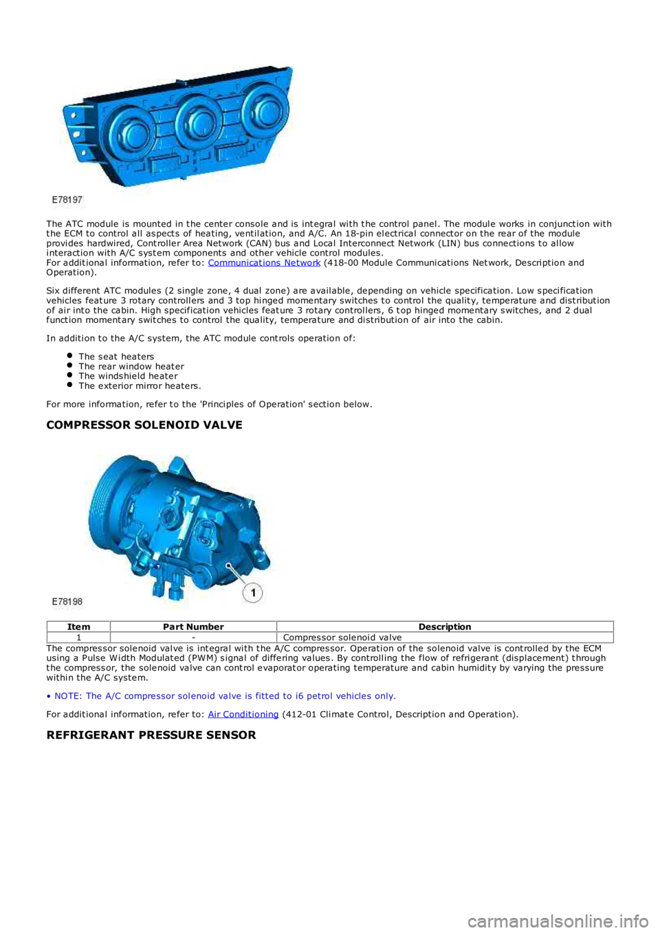
The ATC module is mounted in t he cente r console a nd is int egra l wi th t he control panel . The modul e works in conjunct ion witht he ECM to control a ll as pect s of hea ting, ve ntil ation, and A/C. An 18-pin el ectrical connect or on the re ar of the moduleprovi des hardwired, Cont rolle r Area Network (CAN) bus a nd Loca l Interconne ct Network (LIN) bus conne ctions t o al lowi nteraction with A/C syst em components and other vehicle control modules.For a ddit iona l inf ormation, re fer to: Communicat ions Ne twork (418-00 Module Communi cati ons Net work, De scri ption andO peration).
Six different ATC module s (2 single zone , 4 dual zone) a re a vail able , de pending on vehicle spe cifica tion. Low s peci fica tionvehicles feat ure 3 rotary controll ers and 3 top hi nge d mome ntary switches t o control the qualit y, te mpe rature a nd dist ribut ionof ai r int o the ca bin. High specif icati on vehicles feat ure 3 rotary control lers, 6 top hinge d mome nta ry s witches, and 2 dualf unct ion moment ary swit che s to control the qua lity, tempera ture and di stribution of air into the cabin.
In additi on t o the A/C system, t he ATC module cont rols ope ration of:
The s eat hea tersThe rear window heat erThe winds hie ld he ate rThe e xterior mirror he ate rs.
For more informa tion, re fer t o the 'P rinci ples of O pe ration' s ection below.
COMPRESSOR SOLENOID VALVE
Ite mPart NumberDescription1-Compres sor sole noi d va lveThe compres sor sole noid val ve is int egra l wi th t he A/C compres sor. Ope rati on of the solenoid valve is cont rolle d by the ECMusing a P ulse W i dth Modulat ed (PW M) s igna l of diffe ring va lues . By controll ing the flow of refri gera nt (displace ment) t hrought he compress or, the sole noid va lve can cont rol e vaporat or opera ting temperature and cabin humidit y by va rying the pre ssurewithi n the A/C syste m.
• NO TE: The A/C compre ssor sol enoid va lve is fi tted to i6 petrol vehicle s only.
For a ddit iona l inf ormation, re fer to: Air Conditioning (412-01 Cli mat e Control, Description a nd O peration).
REFRIGERANT PRESSURE SENSOR
Page 1654 of 3229
a utomati c control.
Air distri buti on can be re turned t o automatic control by pres sing the 'AUTO' swi tch loca ted in the ce nte r of the blower motorrotary controller. Thi s wi ll ill uminate the 'AUTO' LED and allow t he ATC module to control a ir di stribution in line wit h it s'comfort' algorithm
Air distri buti on is control led by 2 air dist ribution doors. The ATC module control s the position of the air dis tribution doors byprovi ding LIN bus me ssa ges to t he door ste pper motors . Ha ll ef fect sensors located wit hin the stepper mot ors inform t he ATCmodule t hat moveme nt of the st epper motors is taking place.
ECON - Single Zone Manual System
P ress ing the 'ECO N' moment ary swit ch on the control pa nel will swi tch off t he A/C s yste m. W he n s elected, the ATC modulewill t rans mit a mess age ove r the high speed CAN bus to the ECM re que sting the A/C compressor is dis able d. The ECMdisables the compres sor by de-e nergizing the A/C compress or control re lay loca ted in the BJB. The tell-tale LED in the swit chwill i lluminat e to ale rt the ve hicl e occupants tha t the system is in 'ECO N' mode .
W he n 'ECON' mode i s se lect ed, tempera ture control is s till a vai lable but no cooling of i ntake ai r wi ll ta ke place . The minimumoutput a ir te mpe rature f rom the sys tem will be ambient air tempera ture plus any heat pick up in the ai r int ake pat h.
A/C can be s witched back on by pres sing the 'ECON' swi tch a se cond time. This will als o extinguish the 'ECON' LED.
Stop/Sta rt Ve hicl es - From 2010 MY
From 2010 MY , t he 'ECON' switch wi ll be labeled ‘A/C’ to pre vent confus ion with the ‘Eco’ switch which operates the‘Stop/Sta rt’ a nd 'Gea r Change Indica tor' syst ems .For a ddit iona l inf ormation, re fer to: Starting Sys tem (303-06C Start ing Syst em - TD4 2.2L Diese l, Vehicles Buil t From:01-03-2009, Des cript ion and Ope rati on).
ECON - Dual Zone Automatic System
P ress ing the 'ECO N/O FF' momentary swi tch in the control pa nel will swi tch off t he A/C s yste m. W he n s elected, the ATCmodule will t rans mit a mess age ove r the high speed CAN bus to the ECM re que sting the A/C compress or is dis able d. The ECMdisables the compres sor by de-e nergizing the A/C compress or control re lay loca ted in the BJB. The 'ECO N' t ell-tale LED in t hes witch will il lumi nate to alert the ve hicle occupa nts that the sys tem is i n 'ECON' mode.
W he n 'ECON' mode i s se lect ed, tempera ture control is s till a vai lable but no cooling of i ntake ai r wi ll ta ke place . The minimumoutput a ir te mpe rature f rom the sys tem will be ambient air tempera ture plus any heat pick up in the ai r int ake pat h.
A second pre ss of the 'ECON/OFF' switch wil l ext inguish the 'ECO N' LED and illuminate the 'OFF' LED. W hen in 'OFF' mode t heATC module sets the blower mot or s pee d to 0. Air distri buti on i nto the cabi n wi ll remai n as pre viously sele cted. Al l LED's ont he control pane l wil l be ext inguishe d, a lthough night ti me illumina tion will remain acti ve.
• NO TE: W he n in 'OFF' mode , the he ated se at, heat ed windshie ld a nd heat ed rear window functions wi ll st ill be availa ble.
A thi rd press of t he 'ECO N/O FF' s wit ch re turns the s yste m to norma l (A/C) operation and extinguishes t he 'OFF' LED. Thes yste m can be re turned to a utomati c operat ion at a ny t ime by press ing the 'AUTO' swit ch mounted in t he cent ral (blowermotor) rotary control ler.
Stop/Sta rt Ve hicl es - From 2010 MY
From 2010 MY , t he 'ECON' switch wi ll be labeled ‘A/C’ to pre vent confus ion with the ‘Eco’ switch which operates the‘Stop/Sta rt’ a nd 'Gea r Change Indica tor' syst ems .For a ddit iona l inf ormation, re fer to: Starting Sys tem (303-06C Start ing Syst em - TD4 2.2L Diese l, Vehicles Buil t From:01-03-2009, Des cript ion and Ope rati on).
Programmed Defrost
The programmed def rost function is only ava ilable on ve hicl es fi tted wit h a dua l zone heati ng, vent ilat ion a nd A/C syst em.The f unction is s elected by press ing the 'PRO G' moment ary swit ch on the control pa nel. W hen s ele cted, the ATC moduleprovi des maximum winds hie ld de fros ting/de mist ing by confi guri ng t he s yste m a s follows:
'AUTO ' mode offIntake air set to fres h airAir di stribution se t to windshieldBlowe r motor spe ed s et t o maximumHeate d winds hiel d onRear window hea ter on.
W he n progra mmed defrost is sel ecte d, t he s et t emperat ure will remain unchanged. Programme d de fros t ca n be cancell ed bya ny of the following met hods:
P ress ing any air distribut ion moment ary swit chP ress ing the 'AUTO' s witch locate d in the center of t he blowe r motor rot ary cont rolle rP ress ing the 'PRO G' momenta ry s witch a second time .
• NO TE: Blower motor speed can be adjuste d wi thout te rmi nating programmed defrost.
Windshield Heater
The windshie ld heate r comprises 2 heate r el eme nts , LH and RH, bonded be twee n the glass laminat ions . The s yste m iss witched on by press ing the momentary swi tch l ocat ed on t he control panel . W hen selected, the ATC module t rans mits aheat ing request on t he high spe ed CAN bus to t he CJB. On rece ipt of the messa ge, the CJB ene rgiz es t he windshie ld heate rrelay loca ted in t he BJB by provi ding a ground path for t he relay coi l. The energized rela y provides a ba ttery fe ed t o bothheat er el eme nts . Aft er a period of 4 minutes the ATC module re moves t he request for windshie ld heati ng. The CJB the npowe rs down the windshield hea ter by re moving the ground pat h for the rel ay coil.
The ATC module will only reques t wi ndshield he ater ope rati on if the engine is runni ng. An e ngi ne s tatus si gnal is provi ded tot he ATC module by t he ECM over the high speed CAN bus.
Page 1655 of 3229
Rear Window Heater
The rear window hea ter comprise s a single heat er e leme nt bonded to the inner surf ace of t he glass . The syste m is swi tche don by pre ssing the mome nta ry s witch locate d on the control panel. W he n se lected, the ATC module tra nsmits a he atingreque st on the high spee d CAN bus to the CJB. On recei pt of the me ssa ge, the CJB energiz es t he rear window hea ter relayl ocat ed i n the Auxilia ry Junct ion Box (AJB) by providing a ground pa th for the re lay coil. The energiz ed relay provide s a bat teryf eed to t he heat er e leme nt. Afte r a period of 12 minute s the ATC module re moves the heat ing request . The CJB then powe rsdown the rea r wi ndow he ate r by removing the ground pa th f or t he relay coil .
The ATC module will only reques t re ar window heate r opera tion if the e ngine is running. An engine stat us s ignal is provide d tot he ATC module by t he ECM over the high speed CAN bus.
Exterior Mirror Heaters
O peration of the ext erior mirror heat ers is fully a utomat ic a nd re qui res no input from the driver. The exterior mirror hea tersa re a ctive when the ambient air tempera ture is below 5°C (41°F) and e ngine coolant te mpe rature i s be low 65° C (149° F).Ambi ent air a nd engine coola nt t empera ture val ues are provided by the ECM on the high speed CAN bus. O n re ceipt of the set emperat ure values, the CJB det ermines if e xterior mirror he ating is require d.
The CJB requests exterior mirror hea ting by transmit ting a high spe ed CAN bus mes sage to bot h the drivers and pa sse ngerdoor module s. The door modules provide fee d and ground paths to the respecti ve e xterior mirror he ating el eme nts . W hena mbi ent and engine cool ant tempera ture ris es a bove the va lues sta ted earl ier, the CJB transmi ts a high speed CAN busmess age to the door module s ca nce lling the hea ting reques t.
Seat Heaters
O peration of the sea t he aters is controll ed by the ATC module on re ceipt of a heati ng reque st f rom either of the se at heat ermomenta ry s witches loca ted on the cont rol pane l. The s witches are mounte d in the LH and RH rota ry controllers. A singlepress of a se at heat er switch wi ll implement low level heati ng a nd illumina te a tell-tale LED. A second pre ss of the switch willi mple me nt high l eve l hea ting and ill uminate 2 te ll-t ale LED's. A third press of t he s witch will turn t he s eat hea ter off.
Seat hea ting request s are transmitte d from the ATC module to the seat hea ter control modules on the LIN bus . Two se atheat er control modul es a re f itted, one under each front seat . The se at heat er control modules provide an e lect rical supply tot he s eat hea ter e lement s and a tempera ture sensor loca ted in t he s eat cus hion.
The s eat hea ter cont rol module provides a 5 V reference fee d to the sea t he ate r te mpe rature s ensor. The s eat hea tert emperat ure sensor is an NTC thermistor. By monitoring the ret urne d voltage, t he control module can calculate thet emperat ure of t he s eat. If t he t empera ture rise s above the target tempera ture , the control module wi ll dis abl e operat ion oft he heat er e leme nts .
Page 1747 of 3229
The ambient air t emperat ure s ensor i s a Negati ve Temperature Co-effi ci ent (NTC) thermis t or, and is mount ed in the LeftHand (LH) door mi rror. The s ens or is connect ed t o the Engi ne Cont rol Module (ECM) which t rans mit s an ambi ent ai rt emperature val ue over t he high speed CAN bus . This value i s rel ayed to the ATC modul e by t he Cent ral Junct ion Box (CJB)over t he medium s peed CAN bus.For addit ional informat ion, refer t o: Cont rol Component s (412-01 Cli mat e Cont rol , Descripti on and Operat ion).
REMOTE CONTROL COMPONENTS - VEHICLES FROM 2009MY WITH FFBH REMOTE
CONTROL
The addi ti on of remot e control retai ns the FFBH component s fit ted t o pre 2009MY vehicl es wit h t he addi ti on of thefol lowing components :
FFBH wit h upgraded s oft ware and cali brat ionFFBH remot e handsetFFBH remot e receiverRecei ver power, communicati on and antenna harnes sesAntenna mat chi ng unit harnes s to connect recei ver co-axial cable t o exis t ing DAB antenna in s ide window.
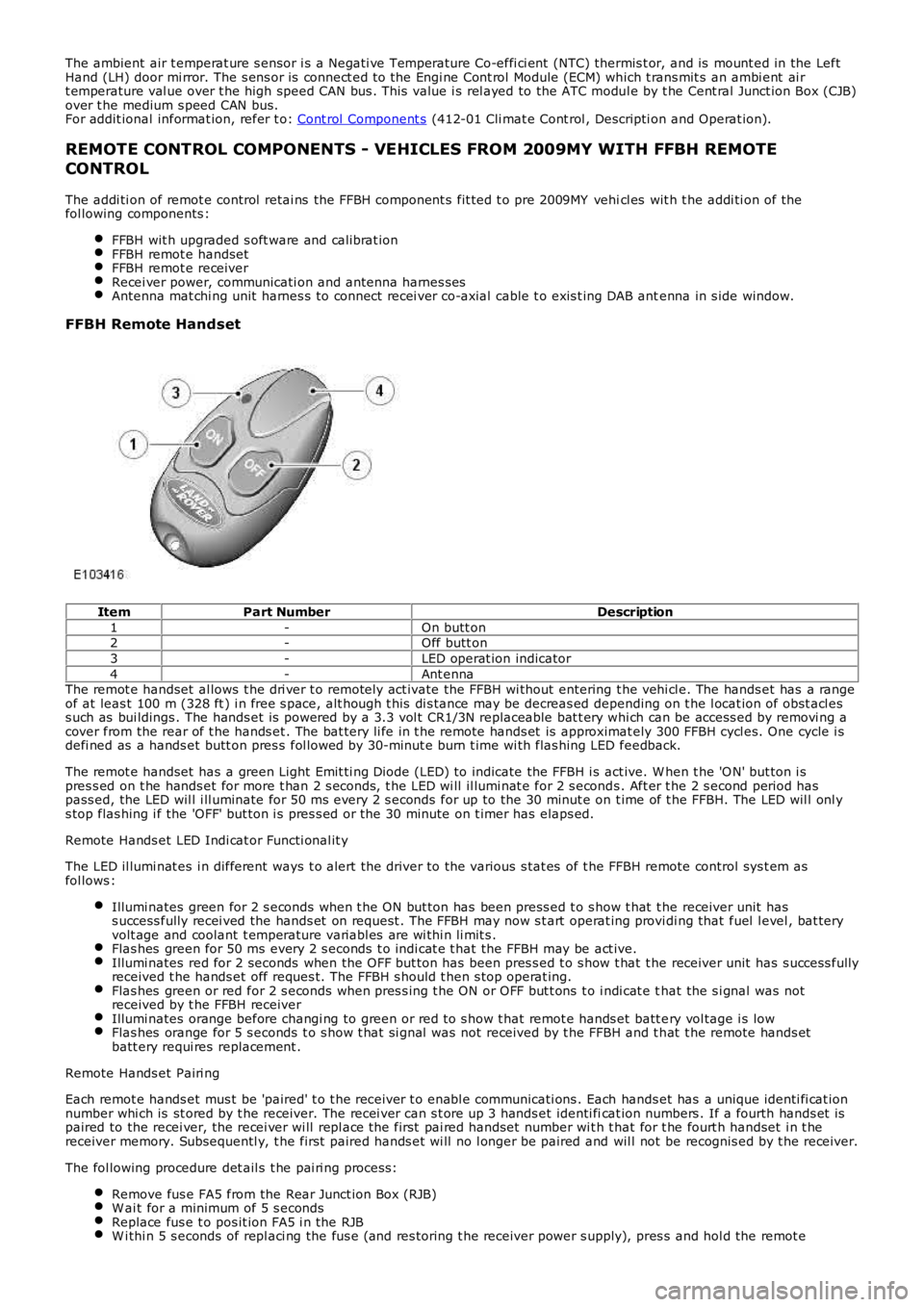
FFBH Remote Handset
ItemPart NumberDescription
1-On butt on2-Off butt on
3-LED operat ion indicator
4-Ant ennaThe remot e handset al lows t he dri ver t o remotely act ivate the FFBH wi thout entering t he vehi cl e. The hands et has a rangeof at leas t 100 m (328 ft ) i n free s pace, alt hough t his di s tance may be decreas ed depending on t he l ocat ion of obst acl ess uch as bui ldings . The hands et is powered by a 3.3 vol t CR1/3N replaceable bat t ery whi ch can be access ed by removi ng acover from the rear of t he hands et . The bat tery li fe in t he remote hands et is approximat ely 300 FFBH cycl es. One cycle i sdefi ned as a hands et butt on pres s fol lowed by 30-minut e burn t ime wi th flas hing LED feedback.
The remot e handset has a green Light Emit ti ng Diode (LED) to indicate the FFBH i s act ive. W hen t he 'O N' but ton i spres s ed on t he hands et for more t han 2 s econds, t he LED wi ll il lumi nat e for 2 s econds . Aft er t he 2 s econd period haspass ed, the LED wil l i ll uminate for 50 ms every 2 s econds for up to the 30 minut e on t ime of t he FFBH. The LED wil l onl ys top flas hing i f the 'OFF' but ton i s pres s ed or the 30 minute on t imer has elaps ed.
Remote Hands et LED Indi cat or Functi onal it y
The LED il lumi nat es i n different ways t o alert the driver to the various s tat es of the FFBH remote control sys t em asfol lows :
Illumi nates green for 2 s econds when t he ON but ton has been press ed t o s how t hat t he receiver unit hass uccess fully recei ved the hands et on request . The FFBH may now s t art operat ing providi ng that fuel l evel , bat teryvolt age and coolant t emperature variabl es are wi thi n li mit s .Flas hes green for 50 ms every 2 s econds t o i ndi cat e t hat the FFBH may be act ive.Illumi nates red for 2 seconds when the OFF but ton has been pres s ed t o s how t hat t he receiver unit has s uccess fullyreceived t he hands et off reques t. The FFBH s hould t hen s top operat ing.Flas hes green or red for 2 s econds when pres s ing t he ON or OFF but t ons t o i ndi cat e that the s i gnal was notreceived by t he FFBH receiverIllumi nates orange before changi ng to green or red to s how t hat remot e hands et batt ery vol tage i s lowFlas hes orange for 5 s econds t o s how t hat si gnal was not received by t he FFBH and t hat t he remote hands etbatt ery requi res replacement .
Remote Hands et Pairi ng
Each remot e hands et mus t be 'paired' t o t he receiver t o enabl e communicati ons . Each hands et has a unique identi fi cat ionnumber whi ch is st ored by t he receiver. The recei ver can s t ore up 3 hands et identi ficat ion numbers . If a fourth hands et ispaired to the recei ver, the recei ver wi ll repl ace the first pai red handset number wit h t hat for t he fourt h handset i n t hereceiver memory. Subsequentl y, t he first paired hands et wi ll no l onger be paired and wil l not be recognis ed by t he receiver.
The fol lowing procedure det ail s t he pai ri ng process :
Remove fus e FA5 from the Rear Junct ion Box (RJB)W ai t for a minimum of 5 s econdsReplace fus e t o pos it ion FA5 i n the RJBW i thi n 5 s econds of repl aci ng the fus e (and res toring t he receiver power s upply), pres s and hol d the remot e
Page 1754 of 3229
s tart fail ure or flameout, and decreas ed by one if a subs equent s tart is succes s ful . If t he event t imer i ncreas es t ot hree (over any number of drive cycl es), the cont rol module ent ers t he error lockout mode.Heat exchanger casing overheat: To prot ect t he s ys t em from exces s ive t emperatures , t he cont rol module ent erst he error l ockout mode if t he heat exchanger coolant temperat ure exceeds 125 °C (257 °F).Battery voltage out of limits: Error lockout wi ll occur if bat tery vol tage fall s bel ow 10.25 or ris es above 15.5 volt s .
The error lockout mode can be cleared usi ng the Land Rover approved di agnos ti c s ys t em, or by dis connect ing the bat terypower supply for a mi nimum of 10 s econds.
Remote Operation - Vehicles from 2009MY with FFBH Remote Control
The 868.3 MHz Radi o Frequency (RF) si gnal s t ransmit ted by the remote hands et are recei ved by the DAB/FFBH ant ennalocated i n t he LH rear s i de window. The s ignal s received by t he antenna are detected by t he FFBH receiver. A 'handshake's ignal is s ent back from the recei ver t o t he hands et t o confirm a val id on or off reques t and act ivate the handset LEDaccordi ngl y. The recei ver proces s es the s i gnal it recei ved and trans mi ts the appropriate si gnal s via a dedi cat ed bus t o theFFBH cont rol module.
• NOTE: The ‘handshake’ si gnal only confi rms hands et-receiver communi cat ions were s uccess ful , and not that t he FFBH hast urned on.
W hen t he FFBH is act ivated by the remote hands et, t he FFBH cont rol module will al low t he FFBH t o operate for 30 minutesor unt il an off request is received from t he remot e hands et or CJB. During t he 30 minut e period, the FFBH may operat e i neit her full l oad combus ti on, part load combus t ion or a controll ed idle phas e of operat ion, depending on t he t emperature oft he coolant i n t he heat exchanger.
Pre-burn Thresholds
The FFBH unit wi ll only acti vat e remotely if t he fol lowing thres hold condit ions are met:
Pre-burn batt ery vol tage check: ≥11.5V (volt age at FFBH terminals )Pre-burn coolant temperat ure check: ≤15°C (int ernal FFBH measurement )Pre-burn fuel l evel check: ≥7.5 lit ers (value s t ored i n FFBH at ignit ion off)
The fuel level val ue s tored wit hin t he FFBH unit i s only updated when t he engine i s running. W hen s t art ing t he FFBH viaremot e control wit h the engi ne off, the fuel l evel value us ed in the FFBH calculat ions wi ll be t hat s t ored at t he las t key offevent . It i s t herefore poss ibl e for t he FFBH t o fai l to operat e remotel y if t he engine was s t opped wi th a low fuel level; i ft he fuel tank i s s ubs equent ly refuell ed, the FFBH s t ored fuel l evel wil l st il l read l ow i f the engine has not been s tarteds ince refuel li ng.
If the FFBH does not act ivate due to low bat tery vol tage or l ow fuel l evel, t he FFBH cont rol module transmit s a mes s age ispass ed on t he medi um and high speed CAN bus es, vi a t he CJB to the i nst rument clus ter mes s age cent er which wil l dis playone of the foll owing mes s ages at i gnit ion on:
AUXILIARY HEATER UNAVAILABLE LOW FUELAUXILIARY HEATER UNAVAILABLE LOW BATTERY .
If bot h l ow fuel and low batt ery volt age mes sages are val id, t he ins trument cl ust er mes sage center wi ll alt ernate bet weent he two mes sages .
Remote Control ‘Park Heat’ to ATC ‘Supplementary Heat’ Transitions
• NOTE: The FFBH can s ti ll be acti vat ed by t he ATC module as previ ous l y descri bed
If the FFBH has been operated remot el y (‘park heat’) and the vehicl e is st art ed whilst the FFBH i s s ti ll act ive, it willt ransi ti on int o t he ATC-control led ‘s upplement ary heat’ mode if t he ATC request s i t.
Shoul d t he ATC t hen send a mess age t o t he FFBH to turn off, the FFBH will remain active if 30 minut es has not yetelaps ed from t he ori ginal remot e cont rol ‘park heat ’ request . Once t he remai nder of 30 mi nut es has elaps ed, t he FFBH wil lt urn off.
Swit chi ng Point Temperatures
W hen remotel y s tarted t he FFBH us es a different s et of s wit chi ng poi nt temperat ures t o t he normal ‘supplement al heat’mode. Thi s is because the remot e s tart feature can s tart the FFBH wi th the engine off – t hus different t hres hol ds arerequired t o opti mis e t he heati ng of the engine coolant.
Swit chi ng Point Temperatures
Page 1827 of 3229
Publi s hed: 11-May-2011
Battery, Mounting and Cables -
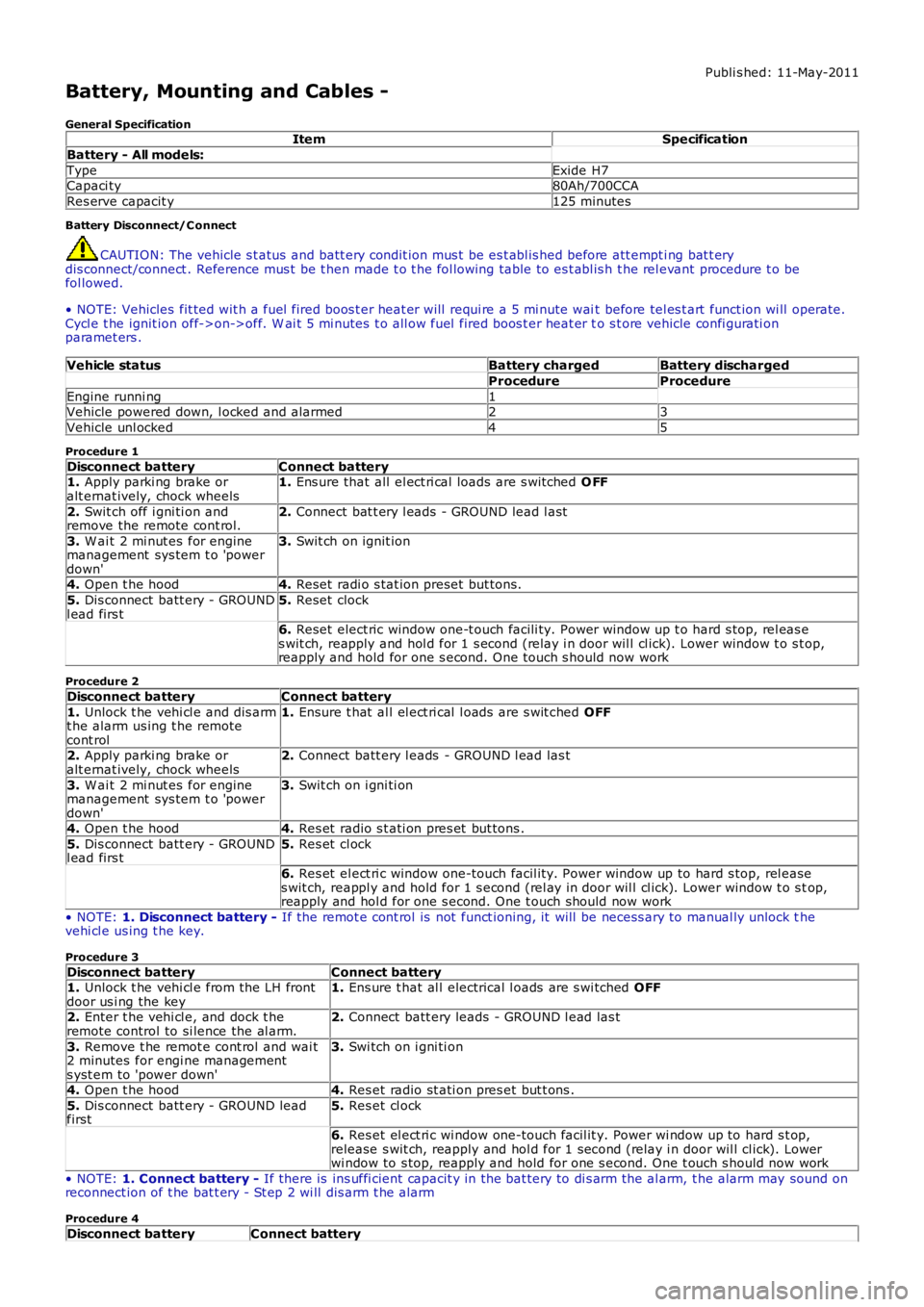
General SpecificationItemSpecification
Battery - All models:
TypeExide H7Capaci ty80Ah/700CCA
Res erve capacit y125 minutes
Battery Disconnect/C onnect
CAUTION: The vehicle s t atus and batt ery condit ion mus t be es t abl is hed before att empti ng bat t erydis connect/connect . Reference mus t be t hen made t o t he fol lowing table to es t abl is h t he rel evant procedure t o befol lowed.
• NOTE: Vehicles fit ted wit h a fuel fired boos t er heat er will requi re a 5 mi nute wait before tel es t art funct ion wi ll operate.Cycl e t he ignit ion off->on->off. W ai t 5 mi nutes t o all ow fuel fired boos t er heat er to s t ore vehicle confi gurati onparamet ers .
Vehicle statusBattery chargedBattery discharged
ProcedureProcedure
Engine runni ng1Vehicle powered down, l ocked and alarmed23
Vehicle unl ocked45
Procedure 1
Disconnect batteryConnect battery1. Apply parki ng brake oralt ernat ively, chock wheels1. Ens ure that all el ect ri cal loads are s wit ched O FF
2. Swit ch off i gni ti on andremove the remote cont rol.2. Connect bat t ery l eads - GROUND lead l ast
3. W ai t 2 mi nut es for enginemanagement sys tem t o 'powerdown'
3. Swit ch on ignit ion
4. Open t he hood4. Reset radi o s tat ion preset but tons .
5. Dis connect batt ery - GROUNDl ead firs t5. Reset clock
6. Reset elect ric window one-t ouch facili ty. Power window up t o hard s top, rel eas es wit ch, reapply and hol d for 1 s econd (relay i n door wil l cl ick). Lower window t o s top,reapply and hold for one s econd. One t ouch s hould now work
Procedure 2
Disconnect batteryConnect battery
1. Unlock t he vehi cl e and dis armt he alarm us ing t he remotecont rol
1. Ensure t hat al l el ect ri cal l oads are s wit ched OFF
2. Apply parki ng brake oralt ernat ively, chock wheels2. Connect batt ery l eads - GROUND l ead las t
3. W ai t 2 mi nut es for enginemanagement sys tem t o 'powerdown'
3. Swit ch on i gni ti on
4. Open t he hood4. Res et radio s t ati on pres et but tons .
5. Dis connect batt ery - GROUNDl ead firs t5. Res et cl ock
6. Res et el ect ri c window one-touch facil it y. Power window up to hard s top, rel eases wit ch, reappl y and hold for 1 s econd (rel ay in door wil l cl ick). Lower window t o s top,reapply and hol d for one s econd. One t ouch should now work
• NOTE: 1. Disconnect battery - If the remot e cont rol is not funct ioning, it will be necess ary to manual ly unlock thevehi cl e us ing t he key.
Procedure 3
Disconnect batteryConnect battery1. Unlock t he vehi cl e from the LH frontdoor us i ng the key1. Ens ure t hat al l electrical l oads are s wi tched OFF
2. Enter t he vehi cl e, and dock t heremote control to si lence the al arm.2. Connect batt ery leads - GROUND l ead las t
3. Remove t he remot e cont rol and wai t2 minutes for engi ne managements yst em to 'power down'
3. Swi tch on i gni ti on
4. Open t he hood4. Res et radio st ati on pres et but t ons .
5. Dis connect batt ery - GROUND leadfirst5. Res et cl ock
6. Res et el ect ri c wi ndow one-touch facil it y. Power wi ndow up to hard s t op,release s wit ch, reapply and hol d for 1 second (relay i n door wil l cl ick). Lowerwi ndow to s top, reapply and hold for one s econd. One t ouch s hould now work
• NOTE: 1. Connect battery - If there is ins uffi cient capacit y in the bat tery to di s arm the al arm, t he alarm may sound onreconnect ion of t he bat t ery - St ep 2 wi ll dis arm t he alarm
Procedure 4
Disconnect batteryConnect battery
Page 1828 of 3229
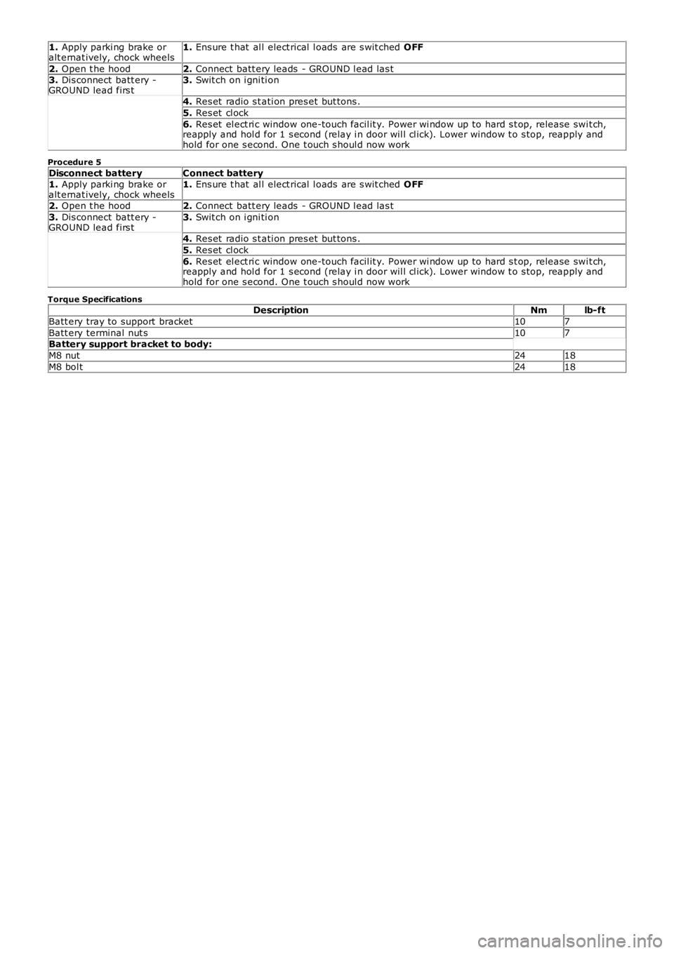
1. Apply parki ng brake oralt ernat ively, chock wheels1. Ens ure t hat al l elect rical l oads are s wit ched OFF
2. Open t he hood2. Connect batt ery leads - GROUND l ead las t3. Dis connect batt ery -GROUND lead firs t3. Swit ch on i gni ti on
4. Res et radio s t ati on pres et but tons .
5. Res et cl ock
6. Res et el ect ri c window one-touch facil it y. Power wi ndow up to hard s t op, release swit ch,reapply and hol d for 1 s econd (relay i n door wil l cl ick). Lower window t o s top, reapply andhold for one s econd. One t ouch s houl d now work
Procedure 5
Disconnect batteryConnect battery1. Apply parki ng brake oralt ernat ively, chock wheels1. Ens ure t hat al l elect rical l oads are s wit ched OFF
2. Open t he hood2. Connect batt ery leads - GROUND l ead las t
3. Dis connect batt ery -GROUND lead firs t3. Swit ch on i gni ti on
4. Res et radio s t ati on pres et but tons .
5. Res et cl ock
6. Res et el ect ri c window one-touch facil it y. Power wi ndow up to hard s t op, release swit ch,reapply and hol d for 1 s econd (relay i n door wil l cl ick). Lower window t o s top, reapply andhold for one s econd. One t ouch s houl d now work
Torque SpecificationsDescriptionNmlb-ft
Batt ery tray to support bracket107
Batt ery terminal nut s107Battery support bracket to body:
M8 nut2418
M8 bol t2418
Page 1912 of 3229

Digi tal Audio Broadcast ing (DAB) s yst em ant enna (s ide screen or roof pod mount ed depending on sys t em)
The AM/FM antenna is et ched ont o t he RH s i de window gl as s . The antenna has an ampli fi er locat ed jus t above thewindow. This ampl ifier wil l vary upon the ent ert ainment and informat ion s yst em fi tt ed to the vehicle. Hi gh li ne s ys t emswil l have a larger ampl ifier for divers i ty t uning.
The rear wi ndow incorporat es 2 FM ant ennae and a VICS/TMC ant enna etched onto t he glas s . The 2 FM ant ennae are us edin the di vers it y tuning sys tem along wi th the res pecti ve antenna ampli fi ers .
The LH s ide window antenna i s used for DAB band III s i gnal recepti on.
• NOTE: The t el ephone control modul e incorporat es a Bl uet ooth ant enna. This i s int egral to the modul e and as s uch is nots erviceabl e.
CONTROL DIAGRAM
• NOTE: A = Hardwi red; P = MOST; T = CoAxial