2006 LAND ROVER FRELANDER 2 fuel pump
[x] Cancel search: fuel pumpPage 558 of 3229
6.
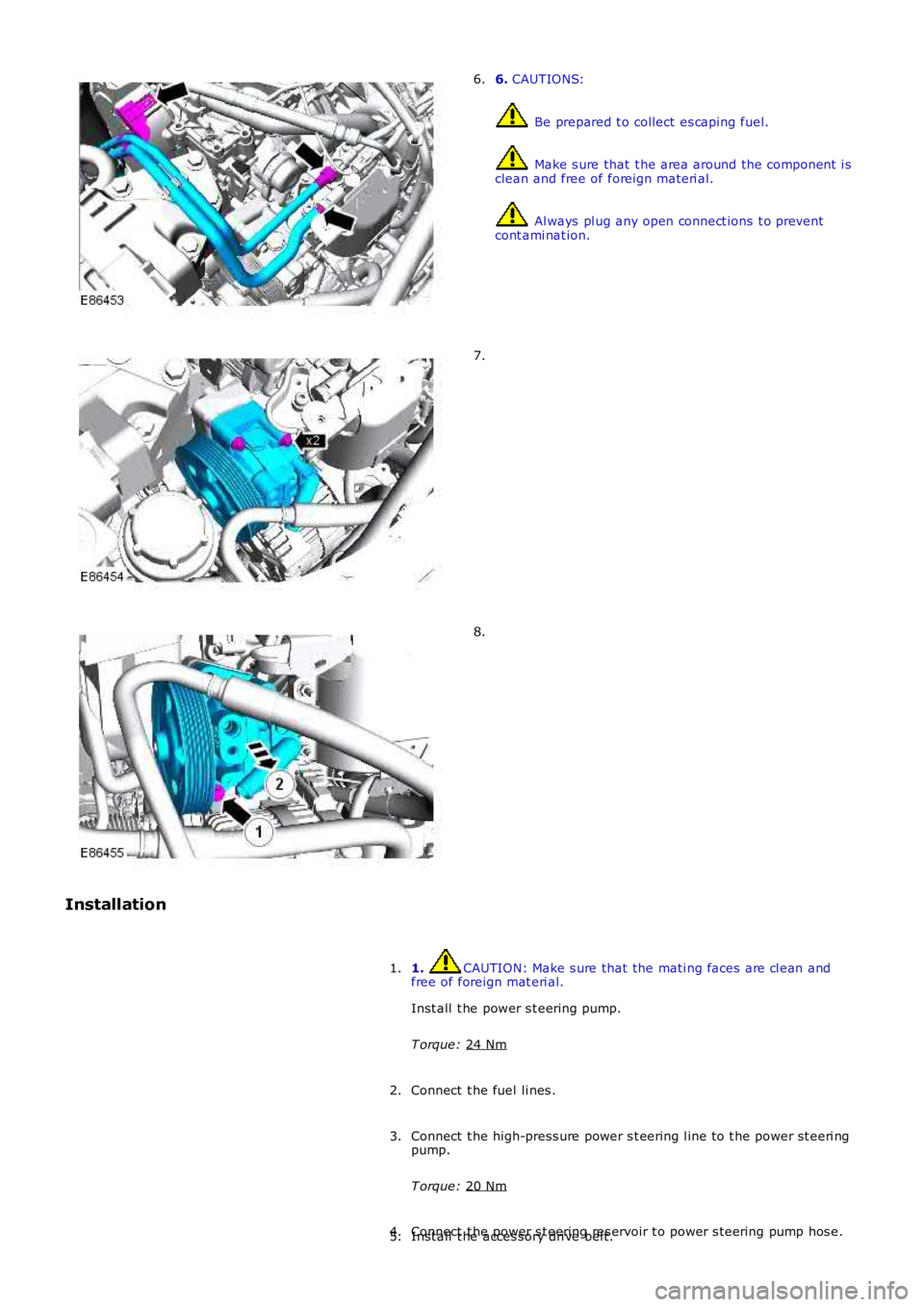
CAUTIONS: Be prepared t o collect es caping fuel.
Make s ure that t he area around the component i s
clean and free of foreign materi al. Al ways pl ug any open connect ions t o prevent
cont ami nat ion.
6. 7.
8.
Installation 1. CAUTION: Make s ure that the mati ng faces are cl ean and
free of foreign mat eri al.
Inst all t he power s t eering pump.
T orque: 24 Nm 1.
Connect t he fuel li nes .
2.
Connect t he high-press ure power s t eering l ine t o t he power st eeri ng
pump.
T orque: 20 Nm 3.
Connect t he power s t eering res ervoir t o power s t eering pump hos e.
4.
Inst all t he acces sory dri ve bel t.
5.
Page 616 of 3229
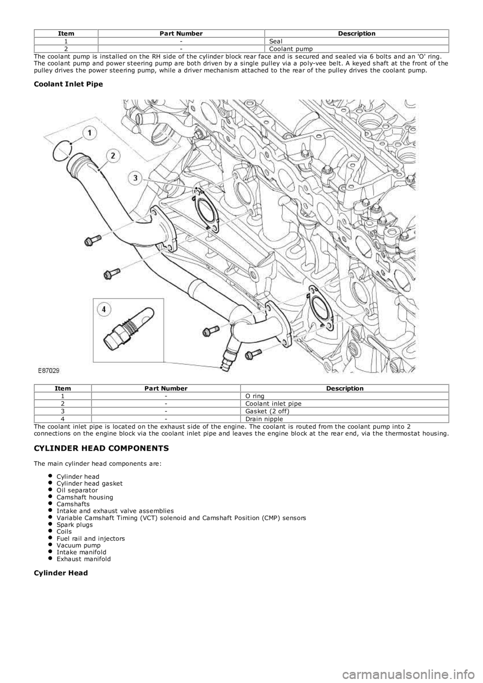
ItemPart NumberDescription1-Seal2-Coolant pumpThe coolant pump is ins t alled on t he RH side of t he cylinder block rear face and is s ecured and s ealed via 6 bolt s and an 'O' ring.The coolant pump and power s t eering pump are bot h driven by a single pulley via a poly-vee belt . A keyed s haft at the front of t hepulley drives t he power s teering pump, while a driver mechanism at t ached to t he rear of t he pulley drives the coolant pump.
Coolant Inlet Pipe
ItemPart NumberDescription1-O ring2-Coolant inlet pipe3-Gas ket (2 off)4-Drain nippleThe coolant inlet pipe is locat ed on t he exhaus t s ide of the engine. The coolant is rout ed from t he coolant pump int o 2connect ions on the engine block via t he coolant inlet pipe and leaves t he engine block at t he rear end, via t he t hermos tat hous ing.
CYLINDER HEAD COMPONENTS
The main cylinder head component s are:
Cylinder headCylinder head gas ketO il s eparat orCams haft hous ingCams haftsIntake and exhaust valve ass embliesVariable Cams haft Timing (VCT) s olenoid and Cams haft Posit ion (CMP) sens orsSpark plugsCoilsFuel rail and injectorsVacuum pumpIntake manifoldExhaus t manifold
Cylinder Head
Page 620 of 3229
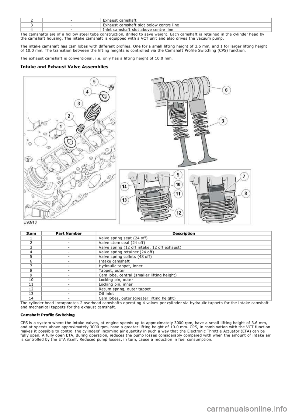
2-Exhaust camshaft3-Exhaust camshaft slot below cent re line4-Inlet camshaft slot above cent re lineThe cams hafts are of a hollow st eel t ube cons t ruction, drilled t o s ave weight . Each camshaft is ret ained in t he cylinder head bythe cams haft hous ing. The int ake cams haft is equipped wit h a VCT unit and also drives the vacuum pump.
The intake camshaft has cam lobes wit h different profiles. One for a small lift ing height of 3.6 mm, and 1 for larger lift ing heightof 10.0 mm. The t ransit ion bet ween t he lift ing height s is cont rolled via the Cams haft Profile Swit ching (CPS) funct ion.
The exhaus t cams haft is convent ional, i.e. only has a lifting height of 10.0 mm.
Intake and Exhaust Valve Assemblies
ItemPart NumberDescription1-Valve s pring s eat (24 off)2-Valve s t em s eal (24 off)3-Valve s pring (12 off int ake, 12 off exhaus t )4-Valve s pring ret ainer (24 off)5-Valve s pring collets (48 off)6-Intake camshaft7-Hydraulic t appet , inner8-Tappet , outer9-Cam lobe, central (s maller lift ing height)10-Locking pin, out er11-Locking pin, inner12-Ret urn s pring, outer tappet13-O il inlet14-Cam lobes , outer (great er lift ing height )The cylinder head incorporat es 2 overhead camshaft s operating 4 valves per cylinder via hydraulic t appet s for the intake camshaftand mechanical t appets for the exhaust cams haft .
Camshaft Profile Sw itching
CPS is a sys tem where t he int ake valves , at engine s peeds up to approximat ely 3000 rpm, have a s mall lifting height of 3.6 mm,and at s peeds above approximat ely 3000 rpm, have a great er lift ing height of 10.0 mm. CPS, in combinat ion wit h t he VCT funct ionmakes it poss ible to cont rol t he cylinders' incoming air quant it y in s uch a way that t he Electronic Throt t le Act uat or (ETA) can befully open. A fully open ETA, during operat ion, reduces t he pump los s es cons iderably compared wit h when the amount of int ake airis controlled by t he ETA its elf. Reduced pump los s es , in turn, cause a reduction in fuel consumpt ion.
Page 628 of 3229
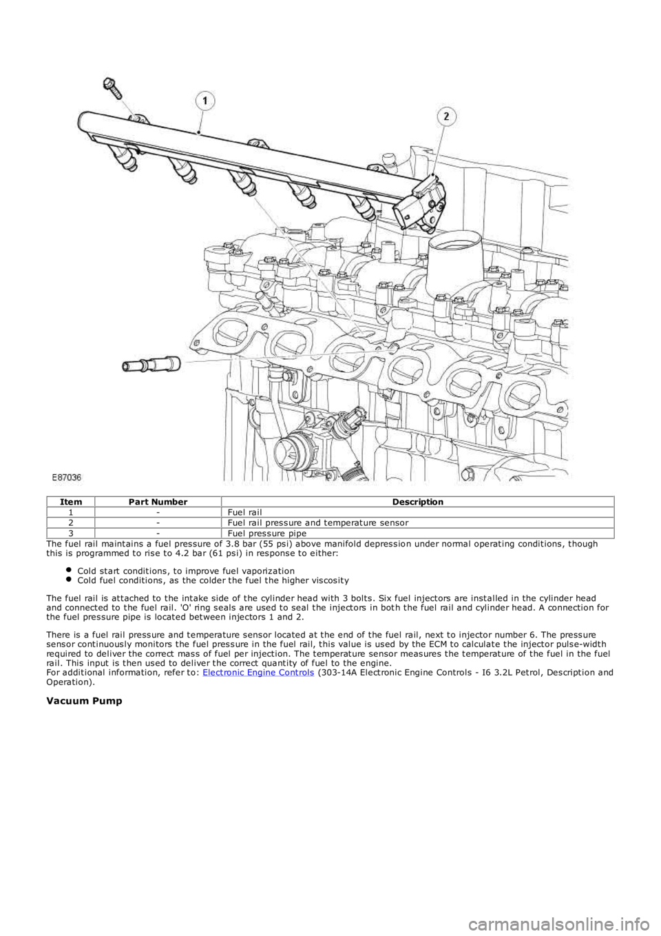
ItemPart NumberDescription1-Fuel rail2-Fuel rail pres s ure and t emperat ure sensor3-Fuel pres s ure pipeThe fuel rail maint ains a fuel pres sure of 3.8 bar (55 ps i) above manifold depres s ion under normal operat ing condit ions , t houghthis is programmed t o ris e t o 4.2 bar (61 ps i) in res pons e t o either:
Cold st art condit ions , t o improve fuel vaporiz ationCold fuel conditions , as the colder t he fuel t he higher vis cos it y
The fuel rail is at t ached to t he int ake s ide of t he cylinder head with 3 bolt s . Six fuel inject ors are inst alled in the cylinder headand connect ed to t he fuel rail. 'O' ring s eals are used t o seal t he inject ors in both t he fuel rail and cylinder head. A connection forthe fuel pres sure pipe is locat ed bet ween injectors 1 and 2.
There is a fuel rail press ure and t emperature s ens or located at t he end of t he fuel rail, next t o injector number 6. The press uresens or cont inuous ly monitors t he fuel pres s ure in the fuel rail, t his value is us ed by the ECM t o calculat e t he inject or puls e-widt hrequired to deliver the correct mas s of fuel per inject ion. The t emperat ure sensor meas ures t he t emperat ure of t he fuel in the fuelrail. This input is t hen us ed to deliver t he correct quant ity of fuel to the engine.For addit ional information, refer t o: Elect ronic Engine Cont rols (303-14A Elect ronic Engine Controls - I6 3.2L Pet rol, Des cript ion andOperation).
Vacuum Pump
Page 647 of 3229
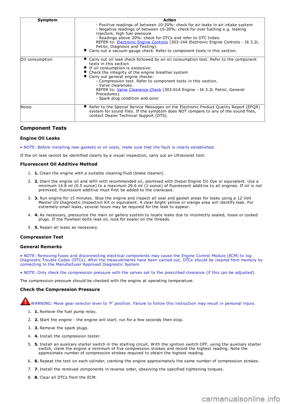
SymptomAction
- Pos it ive readi ngs of bet ween 10-20%: check for air leaks i n air i nt ake s ys t em- Negati ve readings of between 10-20%: check for over fuell ing e.g. leaki ngi njectors , high fuel pres sure- Readings above 20%: check for DTCs and refer t o DTC Index.REFER t o: El ect ronic Engi ne Cont rol s (303-14A El ect roni c Engi ne Cont rol s - I6 3.2LPet rol, Di agnos is and Tes ti ng).Carry out a vacuum gauge check. Refer to component t es ts i n t his s ecti on.
Oi l cons umpti onCarry out oil l eak check fol lowed by an oi l cons umpt ion tes t. Refer t o t he componentt est s i n t hi s s ect ionIf oil cons umpt ion i s exces si ve:Check the integrit y of the engine breat her sys t emCarry out general engi ne checks :- Compress ion tes t. Refer t o component t es ts i n t his s ect ion.- Val ve cl earances .REFER t o: Val ve Clearance Check (303-01A Engine - I6 3.2L Pet rol , GeneralProcedures ).- Spark pl ug condi ti on and col or
Nois eRefer t o t he Speci al Servi ce Mess ages on t he Electroni c Product Q ual it y Report (EPQR)s ys tem for s ound fi les . If t he s ympt om does NOT compare t o any of the s ound files ,contact Deal er Technical Support (DTS).
Component Tests
Engine Oil Leaks
• NOTE: Before ins t al li ng new gasket s or oil s eal s, make sure t hat t he faul t is cl early es t abl is hed.
If the oi l l eak cannot be ident ifi ed clearl y by a vi sual ins pect ion, carry out an Ult raviolet t est :
Fluorescent Oil Additive Method
1. Clean t he engi ne wit h a sui table cl eani ng fl uid (brake cleaner).1.
2. Drai n the engi ne oil and refil l wit h recommended oil , premixed wi th Dies el Engine Oil Dye or equi val ent . Us e aminimum 14.8 ml (0.5 ounce) t o a maxi mum 29.6 ml (1 ounce) of fl uores cent addit ive to all engines. If oil i s notpremixed, fl uorescent addi ti ve mus t fi rs t be added to the crankcas e.
2.
3. Run engi ne for 15 minutes . Stop the engine and i nspect all s eal and gas ket areas for leaks us ing a 12 Vol tMas t er UV Diagnost ic Ins pect ion Ki t or equivalent . A clear bri ght yell ow or orange area wil l i dent ify l eak. Forext remely smal l leaks, s everal hours may be required for t he leak t o appear.
3.
4. As neces s ary, pres surize t he main oil gallery s yst em t o l ocat e leaks due t o incorrect ly sealed, loos e or cockedpl ugs . If the flywheel bol ts l eak oil, l ook for s ealer on t he threads .4.
5. Repai r al l leaks as neces s ary.5.
Compression Test
General Remarks
• NOTE: Removing fuses and di sconnect ing elect rical components may caus e t he Engine Control Modul e (ECM) t o l ogDiagnost ic Troubl e Codes (DTCs ). Aft er t he meas urements have been carried out , DTCs should be cl eared from memory byconnecti ng to the Manufact urer Approved Diagnos t ic Sys tem.
• NOTE: Only check the compress ion pres sure wit h t he valves s et to the pres cri bed clearance (i f thi s can be adjus ted).
The compres si on pres s ure s hould be checked wi th the engine at operat ing temperat ure.
Check the Comp ression Pressure
W ARNING: Move gear s elector lever to 'P' pos i ti on. Fail ure t o follow thi s ins t ructi on may res ult i n pers onal injury.
1. Remove the fuel pump rel ay.1.
2. Start the engine - the engine wi ll s t art, run for a few seconds then s t op.2.
3. Remove the s park pl ugs.3.
4. Ins t al l the compres s ion t es ter.4.
5. Ins t al l an auxi li ary s tarter s wit ch in the st art ing circui t. W it h t he ignit ion swi tch O FF, us ing t he auxi li ary s t arters wi tch, crank the engine a mi ni mum of five compres s ion st rokes and record the hi ghest reading. Not e theapproximat e number of compress i on s trokes requi red t o obt ai n t he highest readi ng.
5.
6. Repeat t he tes t on each cyl inder, cranking t he engine approximat ely t he s ame number of compress i on st rokes .6.
7. Ins t al l the removed components in reverse order, obs erving t he s peci fi ed ti ght ening t orques.7.
8. Clear all DTCs from the ECM.8.
Page 749 of 3229
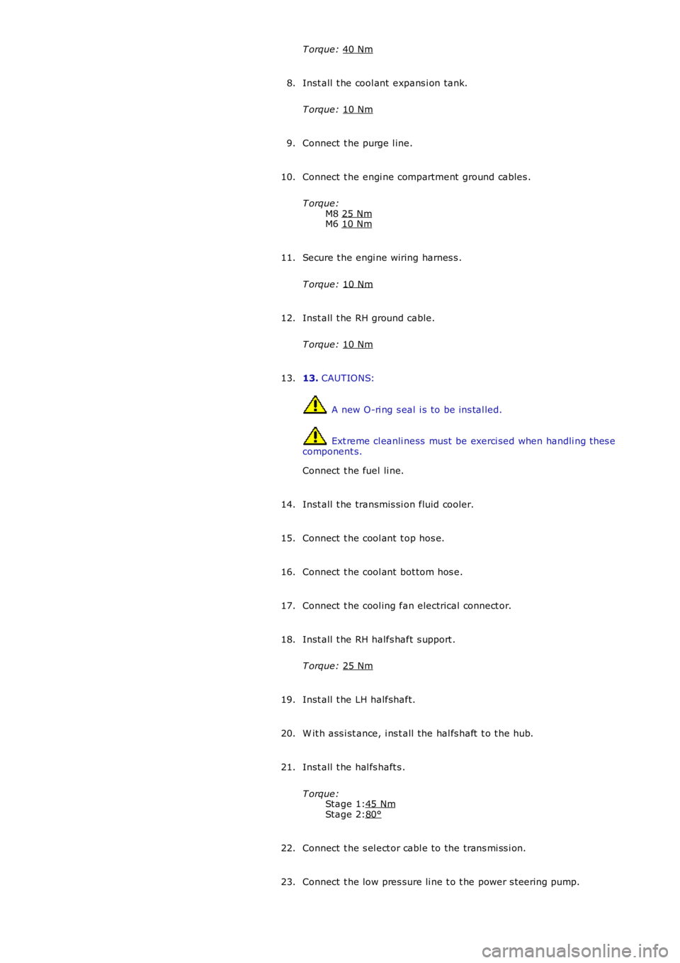
Stage 1:
Stage 2:
T orque:
40 Nm Inst all t he cool ant expans i on tank.
T orque: 10 Nm 8.
Connect t he purge l ine.
9.
Connect t he engi ne compartment ground cables .
T orque: M8 25 Nm M6
10 Nm 10.
Secure t he engi ne wiring harnes s .
T orque: 10 Nm 11.
Inst all t he RH ground cable.
T orque: 10 Nm 12.
13. CAUTIONS: A new O-ri ng s eal i s to be ins tal led.
Ext reme cl eanli ness must be exerci sed when handli ng t hes e
component s.
Connect t he fuel li ne.
13.
Inst all t he transmis si on fluid cooler.
14.
Connect t he cool ant t op hos e.
15.
Connect t he cool ant bot tom hos e.
16.
Connect t he cool ing fan electrical connect or.
17.
Inst all t he RH halfs haft s upport .
T orque: 25 Nm 18.
Inst all t he LH halfshaft.
19.
W it h ass i st ance, i ns t all the hal fs haft t o t he hub.
20.
Inst all t he hal fs haft s .
T orque: 45 Nm 80°21.
Connect t he s el ect or cabl e to the trans mi ss i on.
22.
Connect t he low pres sure li ne t o t he power s t eering pump.
23.
Page 753 of 3229
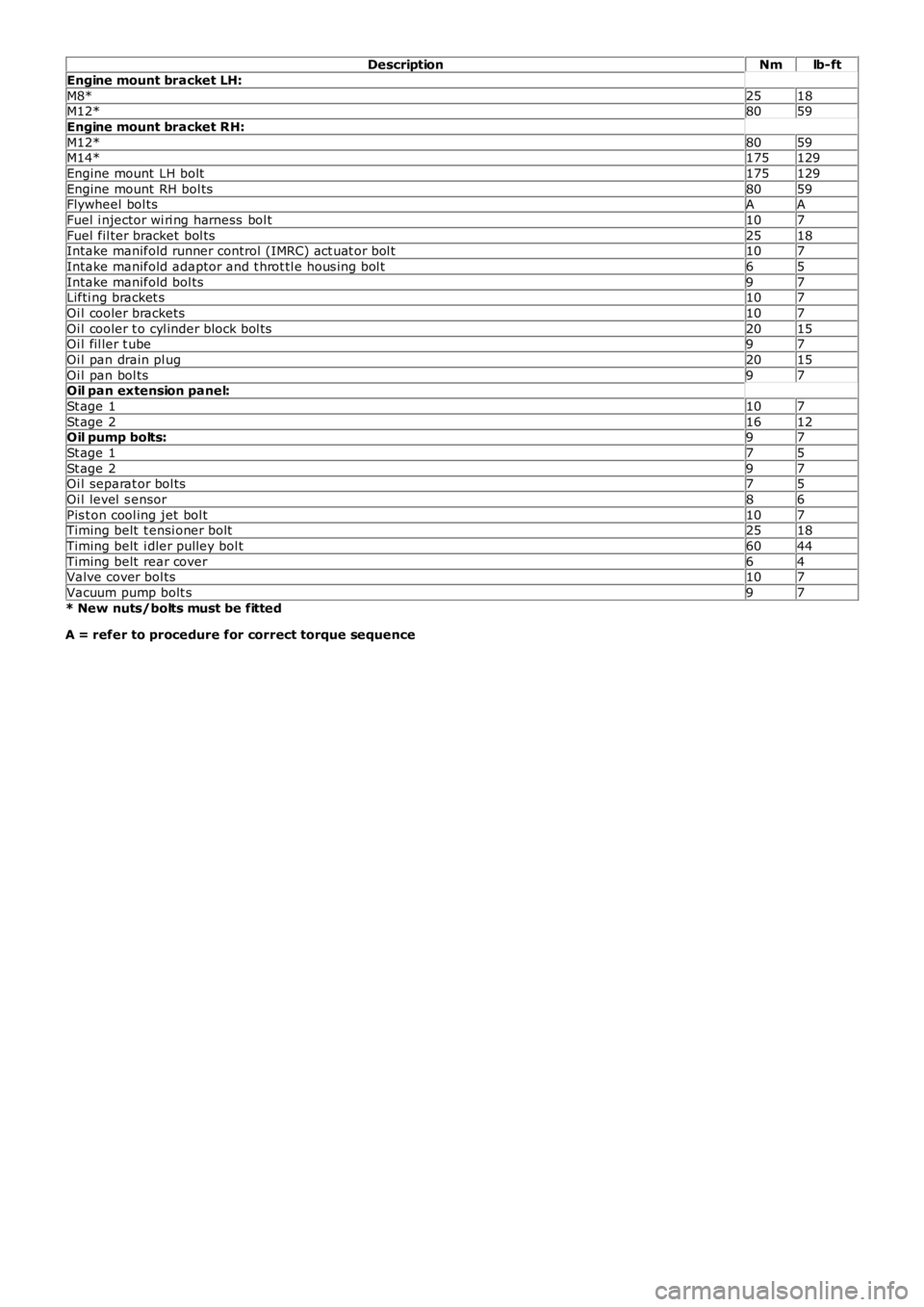
DescriptionNmlb-ft
Engine mount bracket LH:
M8*2518M12*8059
Engine mount bracket RH:
M12*8059M14*175129
Engine mount LH bolt175129
Engine mount RH bol ts8059Flywheel bol tsAA
Fuel i njector wi ri ng harness bol t107
Fuel fil ter bracket bol ts2518Intake manifold runner control (IMRC) act uat or bol t107
Intake manifold adaptor and t hrot tl e hous i ng bol t65
Intake manifold bol ts97Lifti ng bracket s107
Oi l cooler brackets107
Oi l cooler t o cyl inder block bol ts2015Oi l fil ler t ube97
Oi l pan drain pl ug2015
Oi l pan bol ts97Oil pan extension panel:
St age 1107
St age 21612Oil pump bolts:97
St age 175
St age 297Oi l separat or bol ts75
Oi l level s ensor86
Pis t on cool ing jet bol t107Timing belt t ensi oner bolt2518
Timing belt i dler pulley bol t6044
Timing belt rear cover64Valve cover bol ts107
Vacuum pump bolt s97
* New nuts/bolts must be fitted
A = refer to procedure for correct torque sequence
Page 755 of 3229
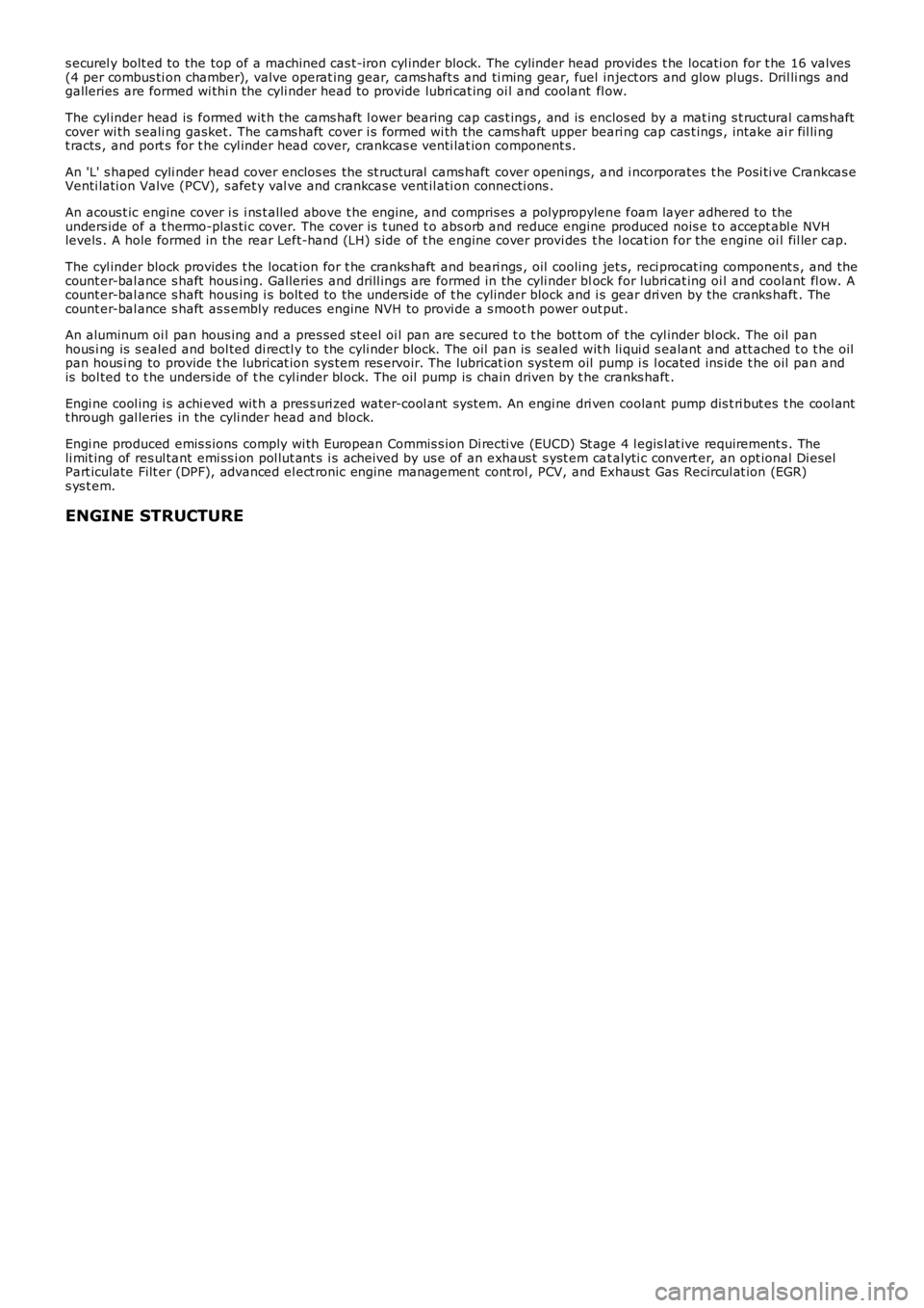
s ecurel y bolt ed to the top of a machined cas t-iron cyl inder block. The cylinder head provides t he locati on for t he 16 valves(4 per combus ti on chamber), valve operat ing gear, cams haft s and ti ming gear, fuel inject ors and glow plugs. Dril li ngs andgalleries are formed wi thi n the cyli nder head t o provide lubri cat ing oi l and coolant fl ow.
The cyl inder head is formed wit h the cams haft l ower bearing cap cas t ings , and is enclos ed by a mat ing s t ructural cams haftcover wi th s eali ng gasket. The cams haft cover i s formed wi th the cams haft upper beari ng cap cas t ings , intake ai r fil li ngt racts , and port s for t he cyl inder head cover, crankcas e venti lat ion component s.
An 'L' s haped cyli nder head cover enclos es the s t ructural cams haft cover openings, and i ncorporates t he Posi ti ve Crankcas eVenti lati on Valve (PCV), s afet y val ve and crankcas e vent il ati on connecti ons .
An acous t ic engine cover i s i ns t alled above t he engi ne, and compris es a polypropylene foam layer adhered to theunders ide of a t hermo-plas ti c cover. The cover i s t uned t o abs orb and reduce engine produced nois e t o accept abl e NVHlevels . A hole formed in the rear Left-hand (LH) s ide of t he engine cover provi des the l ocat ion for the engine oi l fil ler cap.
The cyl inder block provides t he locat ion for t he cranks haft and beari ngs , oil cooling jet s, reci procat ing component s , and thecount er-bal ance s haft hous ing. Galleries and drill ings are formed in the cyli nder block for lubri cat ing oi l and coolant fl ow. Acount er-bal ance s haft hous ing i s bolt ed to the unders ide of t he cylinder block and is gear dri ven by the cranks haft . Thecount er-bal ance s haft as s embly reduces engine NVH to provi de a s moot h power out put .
An aluminum oi l pan hous ing and a pres sed st eel oi l pan are s ecured t o t he bot t om of t he cyl inder bl ock. The oil panhous i ng is s ealed and bol ted di rectl y to the cyli nder block. The oil pan is sealed wit h li qui d s ealant and att ached t o t he oilpan hous i ng to provide t he lubricat ion sys tem res ervoir. The lubricat ion sys tem oil pump i s l ocated ins ide t he oil pan andis bol ted t o t he unders ide of t he cyl inder bl ock. The oil pump is chain driven by t he cranks haft .
Engi ne cool ing i s achi eved wit h a pres s uri zed water-cool ant sys tem. An engi ne dri ven coolant pump dis t ri but es t he cool antt hrough gal leries in the cyli nder head and block.
Engi ne produced emis s ions comply wi th European Commis s ion Di recti ve (EUCD) St age 4 legis l at ive requirement s . Theli mit ing of res ul tant emi ss i on pol lut ant s i s acheived by us e of an exhaus t s yst em cat alyti c convert er, an opt ional Di eselPart iculate Filt er (DPF), advanced el ect ronic engine management cont rol , PCV, and Exhaus t Gas Recircul at ion (EGR)s ys t em.
ENGINE STRUCTURE