Page 839 of 3229
22. CAUTION: The O-ri ng s eal i s to be reus ed
unles s damaged.
• NOTE: Make s ure the fuel pump drive remains capti ve
when removi ng t he fuel pump.
22. 23.
24.
NOTE: The engine is now i n t he SAFE pos i ti on.
Remove the cranks haft t imi ng t ool .
Spec i al T ool(s ): 303-1270 Rotat e t he cranks haft t hrough 90 degrees .24.
Retract and lock the cams haft drive chai n t ens i oner.
25.
Page 841 of 3229

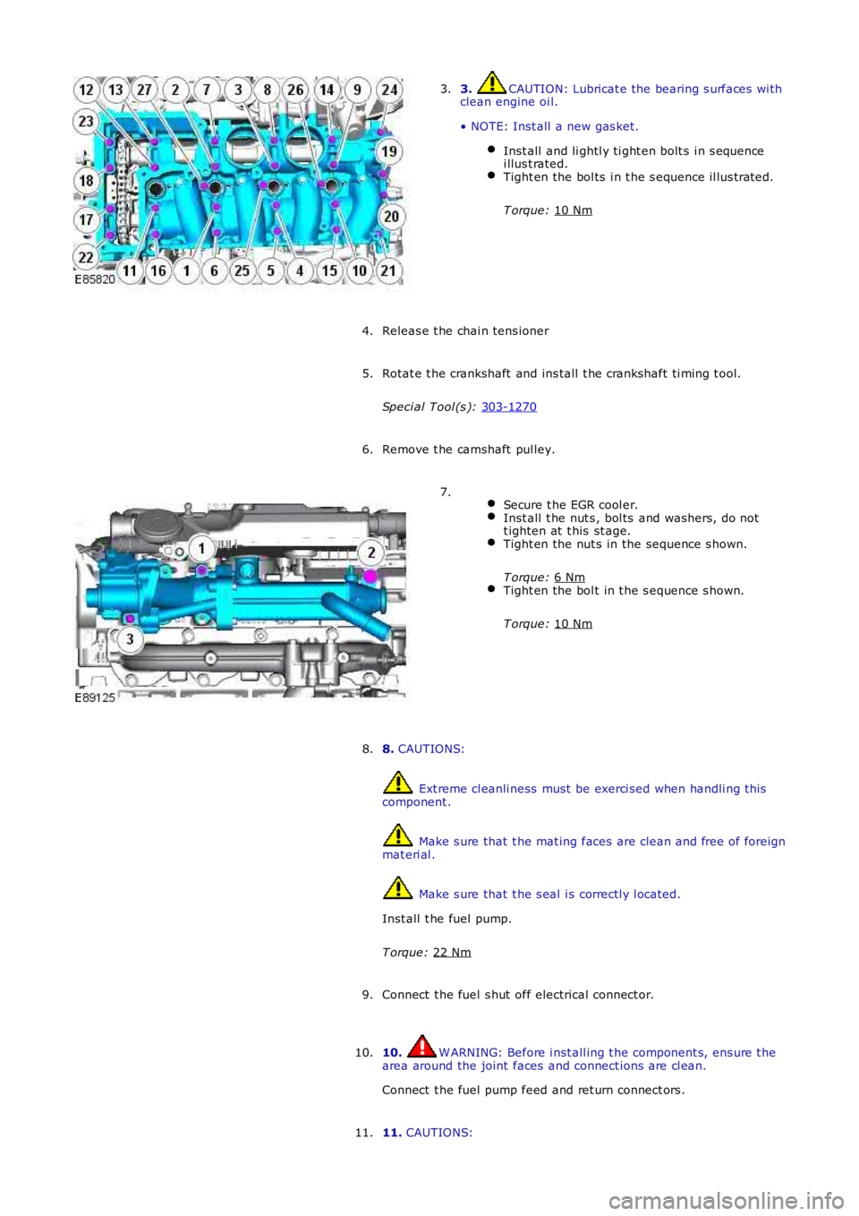
3. CAUTION: Lubricat e the bearing s urfaces wi th
clean engine oi l.
• NOTE: Inst all a new gas ket. Inst all and li ghtl y ti ght en bolt s i n s equence
i llus t rated. Tight en the bol ts i n t he s equence il lus trated.
T orque: 10 Nm 3.
Releas e t he chai n tens ioner
4.
Rotat e t he crankshaft and ins tall t he crankshaft ti ming t ool.
Speci al Tool (s ): 303-1270 5.
Remove t he camshaft pul ley.
6.
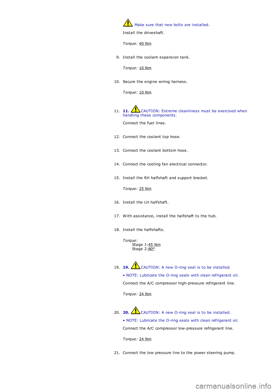
Secure t he EGR cool er. Inst all t he nut s , bol ts and washers, do not
t ighten at t his st age. Tight en the nut s in the sequence s hown.
T orque: 6 Nm Tight en the bol t in t he s equence s hown.
T orque: 10 Nm 7.
8. CAUTIONS: Ext reme cl eanli ness must be exerci sed when handli ng t hi s
component . Make s ure that t he mat ing faces are clean and free of foreign
mat eri al . Make s ure that t he s eal i s correctl y l ocated.
Inst all t he fuel pump.
T orque: 22 Nm 8.
Connect t he fuel s hut off electrical connect or.
9.
10. W ARNING: Before i nst all ing t he component s, ens ure t he
area around the joint faces and connect ions are cl ean.
Connect t he fuel pump feed and ret urn connect ors .
10.
11. CAUTIONS:
11.
Page 842 of 3229
Make s ure that t he mat ing faces are clean and free of foreign
mat eri al . Make s ure that t he s eal i s correctl y l ocated.
Inst all t he vacuum pump.
T orque: 9 Nm Secure t he oil fill er tube.
T orque: 9 Nm 12.
13. CAUTION: Make s ure t hat the mati ng faces are cl ean and
free of foreign mat eri al.
Connect t he vacuum lines t o t he vacuum pump.
13.
Secure t he fuel li nes .
14. 15. CAUTION: Tight en the bol ts i n t he s equence
s hown.
• NOTE: Inst all new s eals .
Inst all t he val ve cover vent oi l separat or.
T orque: 9 Nm 15.
Page 905 of 3229

Stage 1:
Stage 2: Make s ure that new bolt s are ins t al led.
Inst all t he dri ves haft .
T orque: 40 Nm Inst all t he cool ant expans i on tank.
T orque: 10 Nm 9.
Secure t he engi ne wiring harnes s .
T orque: 10 Nm 10.
11. CAUTION: Extreme cleanli nes s mus t be exercis ed when
handl ing t hese components .
Connect t he fuel li nes .
11.
Connect t he cool ant t op hos e.
12.
Connect t he cool ant bot tom hos e.
13.
Connect t he cool ing fan electrical connect or.
14.
Inst all t he RH halfs haft and s upport bracket.
T orque: 25 Nm 15.
Inst all t he LH halfshaft.
16.
W it h ass i st ance, i ns t all the hal fs haft t o t he hub.
17.
Inst all t he hal fs haft s .
T orque: 45 Nm 80°18.
19. CAUTION: A new O-ring s eal is t o be ins tall ed.
• NOTE: Lubri cat e t he O-ring s eals wit h clean refri gerant oil.
Connect t he A/C compress or high-press ure refri gerant line.
T orque: 24 Nm 19.
20. CAUTION: A new O-ring s eal is t o be ins tall ed.
• NOTE: Lubri cat e t he O-ring s eals wit h clean refri gerant oil.
Connect t he A/C compress or low-pres s ure refrigerant li ne.
T orque: 24 Nm 20.
Connect t he low pres sure li ne t o t he power s t eering pump.
21.
Page 939 of 3229

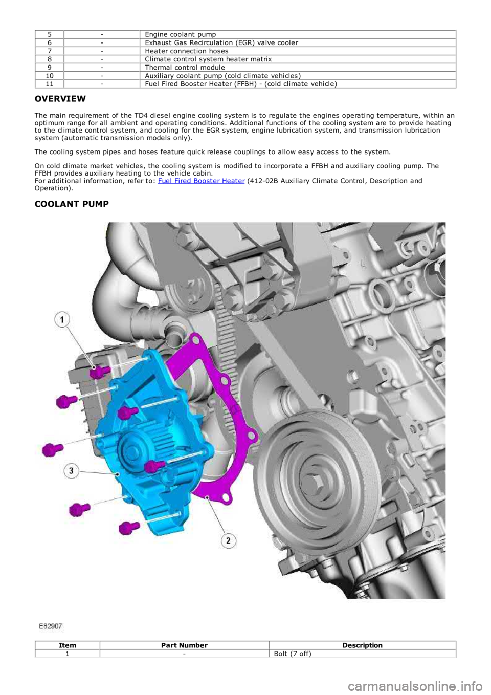
5-Engine coolant pump
6-Exhaus t Gas Recircul at ion (EGR) valve cool er
7-Heat er connect ion hos es8-Cl imat e cont rol s yst em heat er matrix
9-Thermal control modul e
10-Auxil iary coolant pump (col d cli mate vehi cl es )11-Fuel Fi red Boos ter Heater (FFBH) - (cold cli mate vehi cl e)
OVERVIEW
The main requirement of t he TD4 di es el engi ne cool ing s ys tem is t o regul ate t he engines operati ng t emperature, wit hi n anopti mum range for all ambi ent and operat ing condit ions. Addit ional functi ons of t he cool ing s ys tem are to provi de heat ingt o the cl imat e cont rol s ys tem, and cooling for the EGR s ys t em, engi ne lubri cat ion sys tem, and t rans mi ss i on lubri cat ions ys t em (automat ic t rans mis s ion model s only).
The cool ing s ys tem pipes and hoses feature qui ck rel eas e coupl ings t o all ow eas y acces s to the sys tem.
On cold cl imat e market vehicles , the cooli ng s ys t em i s modified t o i ncorporate a FFBH and auxi liary cool ing pump. TheFFBH provides auxili ary heati ng t o t he vehi cl e cabi n.For addit ional informat ion, refer t o: Fuel Fired Boost er Heat er (412-02B Auxi liary Cli mate Cont rol , Des cri pti on andOperat ion).
COOLANT PUMP
ItemPart NumberDescription
1-Bolt (7 off)
Page 946 of 3229

Entrained gases i n t he cool ing s ys tem escape t hrough the t hermal control modul e degas l ine t o t he cool ant res ervoir.
The increas ing coolant temperature is felt at t he t hermos tat , and is regi s tered on the ins trument cl us t er coolantt emperature gage vi a t he ECM and ECT s ens or s i gnal.For addit ional informat ion, refer t o: Ins t rument Clus ter (413-01 Inst rument Cl us t er, Des cript ion and Operat ion).
Engine Normal Operating Temperature
W i th the coolant t emperature increas ing, at 83°C (181°F) t he t hermos tat reacts and commences openi ng. The by-pas svalve is progres s ively clos ed. Hot coolant ret urning from t he engi ne t o t he thermal control modul e i s now all owed to pas st hrough the t op hos e connecti on to the radiator. The fl ow of hot coolant t o t he radiat or now forces cold cool ant wi thi n t heradi at or and bot t om hos e t o fl ow t o t he thermal cont rol module.
Duri ng the thermos t at opening period t here i s an i nit ial temperat ure di fferenti al of t he coolant at bot h s ides of t het hermos tat . The thermos t at react s t o t he t emperature different ial and part iall y closes , whi le t he by-pas s val ve opensfurther. The thermos t at and by-pas s valve conti nue to oscil lat e whil e t he cool ant t emperat ure i ncreas es .
At a coolant temperat ure of 91°C (196°F) t he thermost at is full y opened and t he by-pas s valve i s ful ly clos ed. The returncool ant from t he engi ne is now ful ly circul ated t hrough t he radiat or and bot tom hose. Coolant flows t hrough the radiat orfrom the RH tank t o t he LH t ank, and i s cool ed by air pass i ng through the mat ri x. Ent rai ned gas es i n the radiat or es capet hrough the connect ed degas l ine t o t he cool ant res ervoir.
The increas ed cool ant volume created by heat expans ion caus es the coolant level to ri se through t he connecti ng res ervoirhose, and i nt o t he res ervoi r.
The t emperature of the cooli ng s ys t em i s cons t ant ly moni tored by t he ECM via the ECT s ens or s i gnal. The ECM uses t heECT s ignal to control operati on of the cooling fans , and to adjus t engine fueling. The ECM al so operates t he fans i nres ponse to input s from the aut omati c t ransmis s ion oil t emperat ure s ensor, Air Condit ioning (A/C) s ys tem cont rol s wit ch,and t he A/C pres sure s ens or. For addit ional i nformati on, refer to: El ect ronic Engine Cont rols - 2.2L Di es el (303-14Electroni c Engine Controls - 2.2L Dies el, Des cript ion and Operat ion).For addit ional informat ion, refer t o: Air Condit ioning (412-01 Cli mat e Cont rol , Descripti on and Operat ion).
The cool ing fan s peed is als o infl uenced by vehicle road s peed. The ECM adjus t s the speed of t he cool ing fans tocompens ate for t he ram air effect , us ing t he CAN bus road speed s ignal received from the Ant i-Lock Brake Sys tem (ABS)module.
W hen t he engine i s s hut down, t he coolant t emperature and volume decreas e. The thermos t at st art s t o clos e as t hecool ant t emperat ure decreas es to 89°C (192°F), and is fully cl osed at 81°C (178°F). The coolant level wit hin t he res ervoi rdecreas es as coolant is drawn from the res ervoi r to replenis h the s ys tem.
Followi ng engi ne s hut down when the coolant pump i s s tat ionary, the ECM may cont inue t o operat e t he cool ing fans for apre-det ermined peri od to maint ai n engine cooling.
Page 975 of 3229
Publi s hed: 11-May-2011
Fuel Charging and Controls - I6 3.2L Petrol -
General SpecificationItemSpecification
Recommended fuel:
UK, Europe91 - 98 RONUSAMinimum 91 CLC or AKI
Fuel injectors:
MakeDens o
Fuel Pressures
ComponentbarpsiFuel rail - normal operat ing condit ions - not usi ng IDS3.754
Fuel rail - normal operat ing condit ions - us ing IDS4.868
Fuel rail - engine off - usi ng IDS2.8 to 3.240 t o 46Fuel rail - cold s t art - us ing IDS6.594
Torque Specifications
DescriptionNmlb-ft
Fuel i njector clamp pl ate bol ts65Fuel press ure regulat or bol ts65
Fuel pump drive modul e ret aining bol ts107
Fuel rail bolt s107Fuel rail pres s ure s ens or65
Schreader valve bolt s65
Throt tl e body s crews86
Page 976 of 3229
Publi s hed: 11-May-2011
Fuel Charging and Controls - I6 3.2L Petrol - Fuel Charging and Controls
Des cript ion and Operat ion
Authori ng Templat e
COMPONENT LOCATION
ItemPart NumberDescription1-Fuel rai l
2-Fuel inject or
3-Fuel li ne4-Fuel rai l press ure and fuel temperature s ens or
OVERVIEW
The fuel pump module, l ocat ed in the fuel t ank, i s electronical ly regulated by the Engine Management Sys t em (EMS) toprovide controll ed pres sure in the fuel railFor addit ional informat ion, refer t o: Fuel Tank and Lines (310-01A Fuel Tank and Lines - I6 3.2L Pet rol, Des cri pt ion andOperat ion)..
Suppl yi ng t he correct amount of fuel as required by the engine at any gi ven moment, eli minat es the requirement foraddi ti onal pi pes returning exces s fuel t o t he fuel t ank. The benefit s of t hi s t ype of s ys tem are:
Reduced l oad on the el ect ri cal s yst em