2006 LAND ROVER FRELANDER 2 air condition
[x] Cancel search: air conditionPage 1169 of 3229
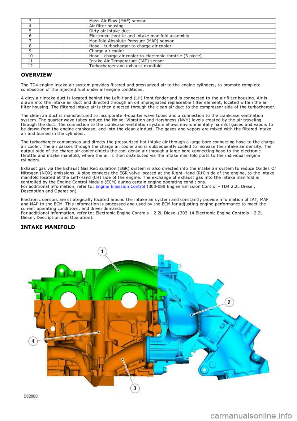
3-Mas s Air Flow (MAF) s ensor
4-Air fil ter housi ng
5-Dirty air int ake duct6-Electroni c t hrott le and int ake mani fol d ass embl y
7-Manifol d Abs olute Pres sure (MAP) sens or
8-Hos e - t urbocharger t o charge air cooler9-Charge air cooler
10-Hos e - charge air cooler to elect roni c thrott le (3 pi ece)
11-Int ake Air Temperat ure (IAT) s ens or12-Turbocharger and exhaus t mani fold
OVERVIEW
The TD4 engine i nt ake air s yst em provides fi lt ered and pres s uri zed ai r to the engine cyli nders , to promote compl etecombus t ion of t he inject ed fuel under al l engine condit ions .
A di rt y air i nt ake duct i s located behind the Left -Hand (LH) front fender and is connect ed to the ai r fi lt er hous ing. Air isdrawn into the i ntake air duct and direct ed through an oil impregnat ed repl aceable fil ter element , locat ed wi thi n the ai rfi lt er hous ing. The filt ered i ntake air i s t hen direct ed through t he clean ai r duct t o the compress or s ide of t he turbocharger.
The clean air duct is manufact ured t o i ncorporat e 4-quarter wave t ubes and a connection to the crankcas e venti lat ions ys t em. The quarter wave t ubes reduce the Noi se, Vi brati on and Hars hnes s (NVH) levels creat ed by t he air t raveli ngt hrough the duct. The connect ion t o t he crankcas e vent il ati on s ys t em al lows environment al ly harmful gas es and vapors tobe drawn from t he engine crankcas e, and int o t he cl ean air duct . The gases and vapors are mi xed wit h t he fi lt ered i ntakeair and burned i n t he cyl inders .
The t urbocharger compres ses and di rects the press uri zed hot i ntake air t hrough a large bore connecti ng hos e to t he chargeair cooler. The ai r pas s es through the charge ai r cooler and i s s ubs equent ly cooled t o i ncreas e t he i nt ake air densi ty. Theoutput s ide of t he charge air cool er direct s the cool dens e ai r through a large bore connecti ng hose to the el ect ronict hrott le and intake mani fold, where the ai r is then dis t ri but ed via the i ntake manifold ports t o t he i ndi vi dual enginecyl inders .
Exhaus t gas via t he Exhaus t Gas Reci rculat ion (EGR) sys t em i s als o direct ed i nt o t he int ake air s yst em t o reduce Oxi des OfNit rogen (NOX) emis s ions . A pipe connect s t he EGR valve l ocat ed at the Ri ght -Hand (RH) s ide of t he engine, to the i ntakemanifold l ocat ed at the Left-Hand (LH) s ide of t he engine. The exchange of exhaust gas i nto t he i nt ake manifold i scont rol led by t he Engine Control Modul e (ECM) during cert ain engine operat ing conditions.For addit ional informat ion, refer t o: Engi ne Emis s ion Cont rol (303-08B Engi ne Emis s ion Cont rol - TD4 2.2L Di esel ,Des cript ion and Operat ion).
Electroni c s ens ors are s t rat egi cal ly l ocat ed around t he int ake ai r s ys t em and const antl y provide i nformat ion of IAT, MAFand MAP t o t he ECM. Thi s i nformat ion i s proces sed and us ed by t he ECM for adjust ing engi ne performance to meet thecurrent operat ing condi ti ons , and driver demands .For addit ional informat ion, refer t o: Electroni c Engi ne Controls - 2.2L Dies el (303-14 El ect ronic Engine Cont rols - 2.2LDies el, Des cript ion and Operat ion).
INTAKE MANIFOLD
Page 1215 of 3229
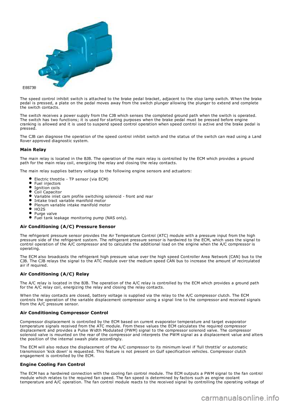
The s peed control inhibit swi tch i s att ached to t he brake pedal bracket , adjacent t o t he s top l amp s wit ch. W hen the brakepedal i s pres s ed, a pl ate on the pedal moves away from t he s wit ch plunger al lowing the pl unger to ext end and completet he swit ch contact s.
The s wit ch receives a power s upply from t he CJB which s enses the complet ed ground path when the s wi tch i s operated.The s wit ch has two functi ons ; it is us ed for s t art ing purpos es when the brake pedal mus t be pres s ed before engi necranking i s allowed and it is used t o s us pend speed cont rol operat ion when s peed cont rol i s act ive and t he brake pedal ispres s ed.
The CJB can diagnos e t he operat ion of t he speed control i nhibit s wi tch and t he s tat us of the s wi tch can read us ing a LandRover approved diagnost ic sys tem.
Main Relay
The main rel ay is l ocat ed in the BJB. The operati on of the mai n rel ay is cont roll ed by t he ECM which provi des a groundpath for the main relay coil , energi zing t he rel ay and cl osi ng t he rel ay cont act s.
The main rel ay suppli es bat t ery volt age to the foll owing engine s ensors and act uators:
Electric t hrot tl e - TP s ensor (via ECM)Fuel i njectorsIgni ti on coi lsCoil Capaci torVari abl e inl et cam profile swit ching sol enoi d - front and rearInt ake tract variable mani fol d mot orPlenum variable i ntake manifold motorHO2SPurge valveFuel t ank leakage monit oring pump (NAS onl y).
Air Conditioning (A/C) Pressure Sensor
The refri gerant pres sure s ens or provides t he Air Temperat ure Cont rol (ATC) module wit h a press ure input from t he highpres s ure s ide of t he refrigerant s ys t em. The refri gerant press ure s ens or is hardwired to the ECM, which us es t he s ignal t ocont rol operat ion of t he A/C compress or and to cal cul at e t he addit ional l oad on t he engi ne when t he A/C compress or isoperati ng.
The ECM al so broadcas ts the refrigerant high press ure val ue over t he high s peed Controller Area Network (CAN) bus t o t heCJB. The CJB relays the si gnal t o t he ATC module over t he medium speed CAN bus t o i ncreas e the amount of recircul at edair i f required.
Air Conditioning (A/C) Relay
The A/C rel ay is l ocat ed in the BJB. The operati on of the A/C relay i s cont roll ed by t he ECM whi ch provi des a ground pat hfor t he A/C rel ay coi l, energizi ng the relay and clos ing the relay cont acts .
W hen t he rel ay cont act s are clos ed, batt ery vol tage i s s uppl ied via the relay t o t he A/C compress or clut ch. The ECMcont rol s the operat ion of t he vari abl e dis placement compress or us ing a s i gnal li ne to t he compress or and received s ignalsfrom the A/C pres s ure sens or.
Air Conditioning Compressor Control
Compres s or di spl acement is cont roll ed by t he ECM bas ed on current evaporator t emperature and target evaporat ort emperature s ignals received from t he ATC module. From thes e values t he ECM calcul ates t he requi red compres s ordis placement and provi des a Puls e W idt h Modul ated (PW M) s i gnal t o t he compress or s olenoi d valve. The compress ors olenoi d valve i s mounted on the rear of t he compres s or and i nterprets the PW M s ignal as a dis placement val ue and alt erst he pos i ti on of the i nternal s wash plate accordi ngl y.
The ECM wi ll als o reduce t he dis placement of the A/C compres s or to i ts mini mum l evel i f 'ful l throt t le' or aut omati ct ransmis s ion 'ki ck down' is request ed. Thi s feat ure i s not pres ent on Gul f s pecificati on vehi cl es. Compress or clutchengagement is cont roll ed by t he ECM.
Engine Cooling Fan Control
The ECM has a hardwired connect ion wit h t he cooli ng fan cont rol module. The ECM output s a PW M s ignal to the fan cont rolmodule whi ch rel at es t o t he required fan s peed. The fan s peed is det ermi ned by factors s uch as engi ne coolantt emperature and A/C operati on. The fan cont rol module react s t o t he received s ignal by cont roll ing t he operat ing volt age of
Page 1218 of 3229
The posi ti on of the inlet cams haft is det ermi ned by the ECM us ing s ignals from t he CKP s ens or and t he CMP s ens ors. TheECM can t hen use the VCT sol enoid val ve to cont rol t he angl e of the cams haft by controlli ng t he fl ow of oil t o t he VCT unit .
The camshaft is s ecured t o t he rot or in t he VCT unit . Oil pres s ure suppli ed to eit her s ide of t he VCT unit from t he VCTs olenoi d valve can rot ate the rotor and hence the cams haft i n eit her di recti on. The VCT sol enoi d is operat ed by t he ECMus ing PW M, hi gh frequency s wit chi ng which provi des rapid and preci se cont rol of the i nlet cams haft pos i ti on. The i nletcamshaft pos i ti on can be adjust ed wi thi n 40 degrees of cranks haft rotat ion.
Camshaft Profile Switching (CPS) Control
The inl et cams haft has , in addit ion to t he VCT control, a CPS funct ion whi ch is al so cont roll ed by t he ECM. The CPS cont rolcan vary t he val ve li ft height and durat ion of t he camshaft lobes by adjus ti ng the area of t he hydraul ic t appet whi ch act son one of t wo cam l obe profi les . The CPS cont rol is vi a t wo CPS s olenoid valves , located at each end of the i nlet cams haft.The CPS s olenoid valves cont rol t he posi ti on of hydraul ic t appet as s embli es which can be s et in one of t wo pos it ions; lowand high.
Two CPS s olenoids are us ed so that t he hydraul ic t appet s can be adjus t ed when no load i s applied, for example the camlobes are off t he hydraul ic t appet s and t he cam bas e circl e is act ing on t he t appet , thi s keeps t he s tress on components toa minimum. One CPS s ol enoi d s uppl ies oi l press ure to the hydrauli c t appet s of cyli nders 1, 2 and 4 and the s econd CPSs olenoi d s uppl ies oi l press ure to the tappet s of cylinders 3, 5 and 6.
At engi ne s tart and at low engine oi l temperat ures (below 40°C (104°F)) the ECM does not direct engine oi l pres sure t ot he hydraul ic t appet s and t herefore the hydraul ic t appet s are in t heir s pring loaded, l ow posi ti on.For addit ional informat ion, refer t o: Engi ne - 3.2L (303-01, Descripti on and Operat ion).
Ignition Control
The ECM calculat es the opt imum ignit ion ti ming bas ed on pre-programmed maps and informat ion from t he foll owings ens ors :
CKP s ensorCMP s ensorsMAF s ensorECT s ens orElectric t hrot tl e TP s ensorKnock s ens orsTCMIgni ti on coi ls .
Duri ng engi ne s tarti ng the ECM uses a fi xed ignit ion s et ti ng. W hen the engine has s tart ed and the vehicle is bei ng driven,t he ECM adjus ts the i gni ti on t imi ng accordi ngl y us ing ot her paramet ers s uch as engine s peed, l oad and temperat ure.
Once the engi ne has reached i ts normal operati ng temperature, t he ECM moni tors the si gnal s from the knock sens ors . Ifany of the cyli nders produce knocking, the i gnit ion t imi ng for t hat cyli nder wi ll be retarded unt il t he knocking has s t opped.The ignit ion is t hen gradually advanced back t o t he normal t imi ng or unt il t he knocking re-occurs .
The ECM us es informat ion from the TCM t o provide t orque l imi tat ion during t rans mis s ion s hifts . The i gni ti on ti mi ng isadjus ted t o moment ari ly reduce t he engine t orque output t o give a smoot h t rans mis s ion shi ft and reduce l oad on thet ransmis s ion.
Air Conditioning (A/C) Compressor Control
The ECM controls t he operati on of the A/C compres s or and reacts t o reques ts from t he ATC module vi a t he high s peed CANbus. The compres s or is a variable di s pl acement unit and t he ECM controls , via a sol enoi d, t he dis placement of thecompres sor t o adjus t load during cert ain driving condit ions.
Duri ng engi ne s tart-up, movi ng from a s tandst il l and under hard accelerat ion, the ECM s et s t he mi nimum dis placement oft he compress or t o reduce the effect on t he engi ne t orque output. The ECM uses i nformati on from t he ATC module, t he A/Cpres s ure s ensor, the el ect ri c t hrott le TP s ens or and the ECT sens or to det ermi ne compres sor control . The ATC modulet ransmit s climate control and driver reques ts t o t he ECM and t he ECM det ermi nes the priori ty of thes e request s overengi ne performance.
Page 1360 of 3229
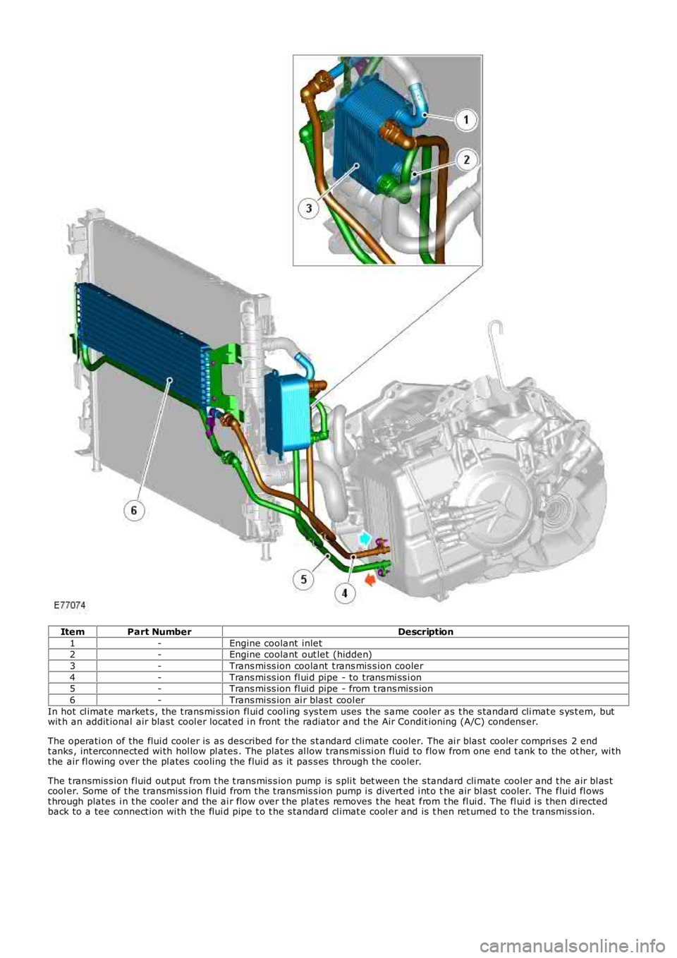
ItemPart NumberDescription
1-Engine coolant inlet2-Engine coolant out let (hidden)
3-Trans mi ss ion coolant t rans mis s ion cooler
4-Trans mi ss ion fl ui d pipe - to trans mi ss i on5-Trans mi ss ion fl ui d pipe - from t rans mis s ion
6-Trans mi ss ion ai r blas t cool er
In hot cl imat e market s , the t rans mi ss ion fl ui d cool ing s ys tem uses the s ame cooler as t he s tandard cli mat e s ys t em, butwit h an addit ional air blas t cool er locat ed i n front the radiator and t he Air Conditioning (A/C) condens er.
The operati on of the flui d cool er is as des cribed for the s t andard climate cooler. The ai r blas t cooler compri s es 2 endt anks , int erconnected wi th hol low pl ates . The plat es al low trans mi s si on fl uid t o flow from one end t ank to the ot her, wi tht he air fl owing over the pl ates cooling the flui d as it pas s es through t he cooler.
The t ransmis s ion fluid out put from t he t rans mis s ion pump is s pli t bet ween t he s tandard cli mate cool er and t he air bl as tcool er. Some of t he transmis s ion fluid from t he t ransmis s ion pump i s divert ed i nt o the air bl as t cooler. The flui d fl owst hrough plates i n t he cool er and the ai r flow over t he plat es removes t he heat from t he fl ui d. The fl ui d i s then di rectedback to a tee connect ion wi th the flui d pipe t o t he s tandard cl imat e cool er and is then ret urned t o t he transmis s ion.
Page 1630 of 3229
Publi s hed: 11-May-2011
Climate Control System - General Information - Air Conditioning (A/C)
System Recovery, Evacuation and Charging
General Procedures
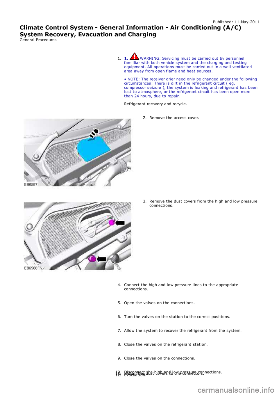
1. W ARNING: Servicing mus t be carried out by pers onnelfamil liar wi th bot h vehicle s ys tem and the chargi ng and tes t ingequipment. Al l operat ions mus t be carried out i n a wel l vent ilat edarea away from open flame and heat s ources .
• NOTE: The receiver dri er need onl y be changed under t he followi ngcircums t ances : There i s dirt in t he refri gerant ci rcuit ( eg.compres s or s eizure ), t he s yst em is l eaking and refrigerant has beenl os t t o at mosphere, or t he refri gerant ci rcuit has been open moret han 24 hours , due to repair.
Refrigerant recovery and recycle.
1.
Remove t he acces s cover.2.
Remove t he dus t covers from the hi gh and low pres sureconnecti ons .3.
Connect t he high and l ow pres s ure l ines t o t he appropriat econnecti ons .4.
Open t he valves on t he connect ions .5.
Turn the valves on t he s tat ion t o t he correct pos it ions.6.
All ow t he s yst em t o recover the refrigerant from the sys tem.7.
Clos e t he valves on t he refri gerant st ati on.8.
Clos e t he valves on t he connecti ons .9.
Di sconnect t he high and l ow pres s ure connect ions.10.Inst all t he dus t covers t o t he connect ors .11.Evacuati on.12.
Page 1638 of 3229
Publi s hed: 11-May-2011
Climate Control - Air Conditioning
Des cript ion and Operat ion
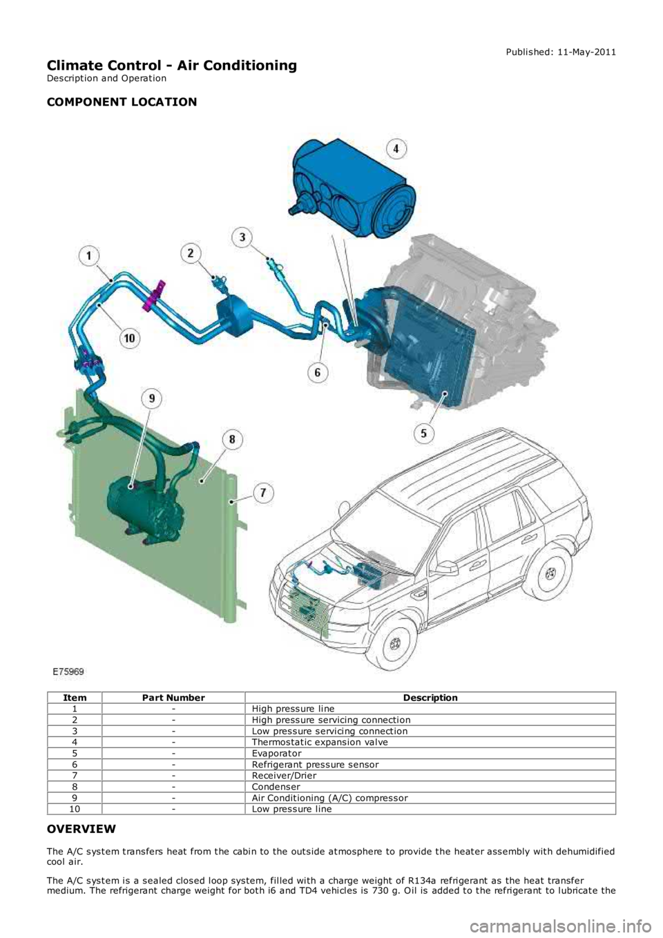
COMPONENT LOCATION
ItemPart NumberDescription1-High press ure li ne
2-High press ure servicing connecti on
3-Low pres s ure s ervi ci ng connect ion4-Thermos tat ic expans ion val ve
5-Evaporat or
6-Refrigerant pres s ure s ensor7-Receiver/Drier
8-Condens er
9-Air Condit ioning (A/C) compres s or10-Low pres s ure l ine
OVERVIEW
The A/C s ys t em t rans fers heat from t he cabi n to the out s ide at mosphere to provide t he heat er ass embly wit h dehumidifiedcool air.
The A/C s ys t em i s a s ealed clos ed l oop sys tem, fil led wi th a charge weight of R134a refri gerant as the heat transfermedium. The refrigerant charge weight for bot h i6 and TD4 vehi cl es is 730 g. O il is added t o t he refri gerant to l ubricat e the
Page 1646 of 3229
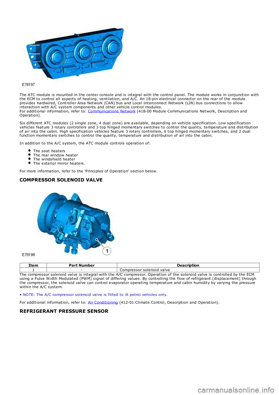
The ATC module is mounted in t he cente r console a nd is int egra l wi th t he control panel . The modul e works in conjunct ion witht he ECM to control a ll as pect s of hea ting, ve ntil ation, and A/C. An 18-pin el ectrical connect or on the re ar of the moduleprovi des hardwired, Cont rolle r Area Network (CAN) bus a nd Loca l Interconne ct Network (LIN) bus conne ctions t o al lowi nteraction with A/C syst em components and other vehicle control modules.For a ddit iona l inf ormation, re fer to: Communicat ions Ne twork (418-00 Module Communi cati ons Net work, De scri ption andO peration).
Six different ATC module s (2 single zone , 4 dual zone) a re a vail able , de pending on vehicle spe cifica tion. Low s peci fica tionvehicles feat ure 3 rotary controll ers and 3 top hi nge d mome ntary switches t o control the qualit y, te mpe rature a nd dist ribut ionof ai r int o the ca bin. High specif icati on vehicles feat ure 3 rotary control lers, 6 top hinge d mome nta ry s witches, and 2 dualf unct ion moment ary swit che s to control the qua lity, tempera ture and di stribution of air into the cabin.
In additi on t o the A/C system, t he ATC module cont rols ope ration of:
The s eat hea tersThe rear window heat erThe winds hie ld he ate rThe e xterior mirror he ate rs.
For more informa tion, re fer t o the 'P rinci ples of O pe ration' s ection below.
COMPRESSOR SOLENOID VALVE
Ite mPart NumberDescription1-Compres sor sole noi d va lveThe compres sor sole noid val ve is int egra l wi th t he A/C compres sor. Ope rati on of the solenoid valve is cont rolle d by the ECMusing a P ulse W i dth Modulat ed (PW M) s igna l of diffe ring va lues . By controll ing the flow of refri gera nt (displace ment) t hrought he compress or, the sole noid va lve can cont rol e vaporat or opera ting temperature and cabin humidit y by va rying the pre ssurewithi n the A/C syste m.
• NO TE: The A/C compre ssor sol enoid va lve is fi tted to i6 petrol vehicle s only.
For a ddit iona l inf ormation, re fer to: Air Conditioning (412-01 Cli mat e Control, Description a nd O peration).
REFRIGERANT PRESSURE SENSOR
Page 1712 of 3229
Publi s hed: 11-May-2011
Climate Control - Air Conditioning (A/C) CompressorI6 3.2L Petrol
Removal and Inst all ati on
Removal
CAUTION: Make s ure that the specified amount of refrigerant oi l is added.
Remove t he cover and dis connect the bat tery ground cabl e.
Refer t o: Specificati ons (414-00 Bat tery and Charging Sys tem -General Informat ion, Specificati ons).
1.
Recover t he air condi ti oni ng (A/C) refri gerant .
Refer t o: Air Condi ti oning (A/C) Sys tem Recovery, Evacuati on andCharging (412-00 Cl imat e Control Sys t em - General Informat ion,General Procedures).
2.
Remove t he engi ne cover.
Refer t o: Engi ne Cover - I6 3.2L Pet rol (501-05 Int eri or Trim andOrnament ati on, Removal and Ins tal lat ion).
3.
Remove t he bat t ery t ray.
Refer t o: Bat t ery Tray (414-01 Bat tery, Mount ing and Cables ,Removal and Ins tall ati on).
4.
Remove t he air cleaner as s embly.
Refer t o: Air Cleaner (303-12A Intake Ai r Dis tribut ion and Fil tering -I6 3.2L Pet rol, Removal and Ins t al lat ion).
5.
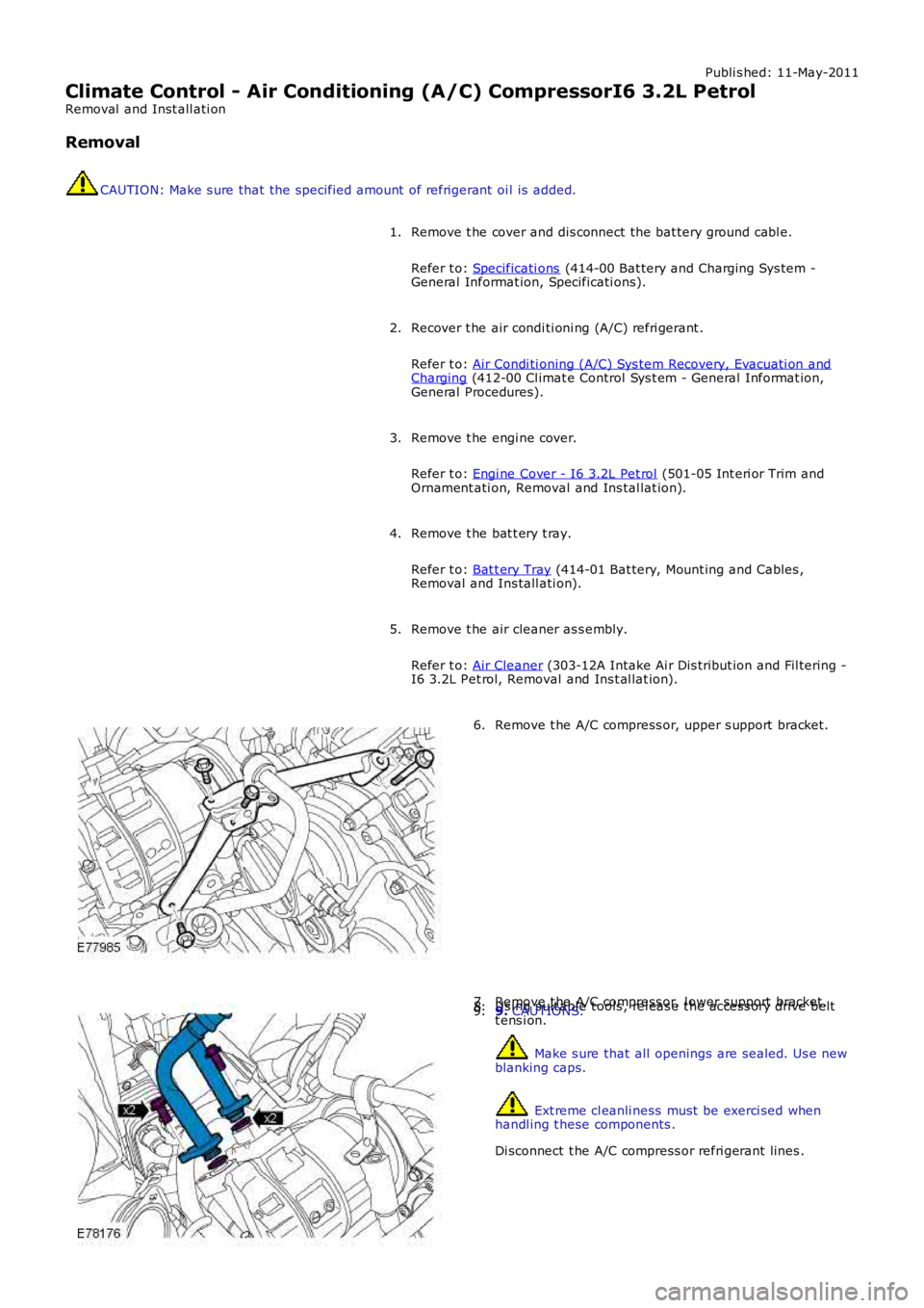
Remove t he A/C compress or, upper s upport bracket.6.
Remove t he A/C compress or, l ower support bracket.7.Us ing s uit able t ools , rel eas e t he acces s ory drive beltt ens i on.8.9. CAUTIONS:
Make s ure that all openings are sealed. Us e newblanking caps.
Ext reme cl eanli ness must be exerci sed whenhandl ing t hese components .
Di sconnect t he A/C compress or refri gerant lines .
9.