2006 LAND ROVER FRELANDER 2 air condition
[x] Cancel search: air conditionPage 1715 of 3229
Publi s hed: 11-May-2011
Climate Control - Air Conditioning (A/C) CompressorTD4 2.2L Diesel
Removal and Inst all ati on
Removal CAUTION: Make s ure that the specified amount of refrigerant oi l is added.
• NOTE: Removal s t eps in t his procedure may cont ain i nst all ati on det ail s.
Di sconnect t he bat t ery ground cable.
Refer t o: Specificati ons (414-00 Bat tery and Charging Sys tem -
General Informat ion, Specificati ons).
1.
Recover t he A/C refrigerant .
Refer t o: Air Condi ti oning (A/C) Sys tem Recovery, Evacuati on and Charging (412-00 Cl imat e Control Sys t em - General Informat ion,
General Procedures).
2. 3.
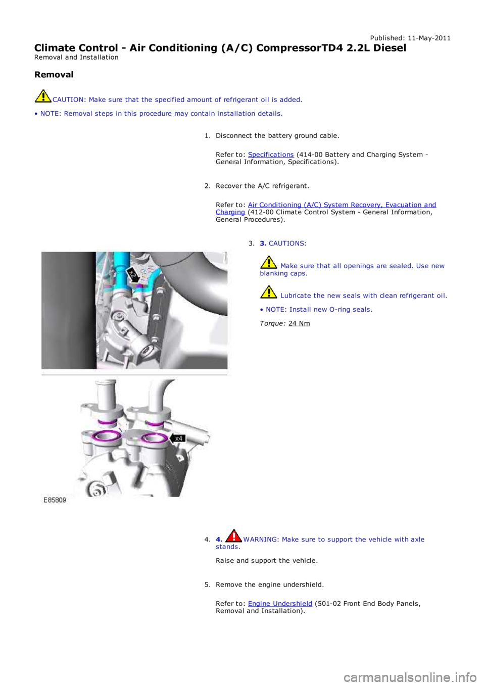
CAUTIONS: Make s ure that all openings are sealed. Us e new
blanking caps. Lubri cat e t he new s eals wi th cl ean refrigerant oi l.
• NOTE: Inst all new O-ring s eals .
T orque: 24 Nm 3.
4. W ARNING: Make sure t o s upport the vehicle wit h axle
s tands .
Rais e and s upport t he vehi cl e.
4.
Remove t he engi ne undershi eld.
Refer t o: Engi ne Unders hi eld (501-02 Front End Body Panel s ,
Removal and Ins tall ati on).
5.
Page 1727 of 3229
Publi s hed: 11-May-2011
Climate Control - Air Conditioning (A/C) Pressure Transducer
Removal and Inst all ati on
Removal
• NOTE: Removal s t eps in t his procedure may cont ain i nst all ati on det ail s.
Remove t he plenum chamber.
Refer t o: Plenum Chamber (412-01 Cl imat e Control, Removal and
Inst all at ion).
1. 2.
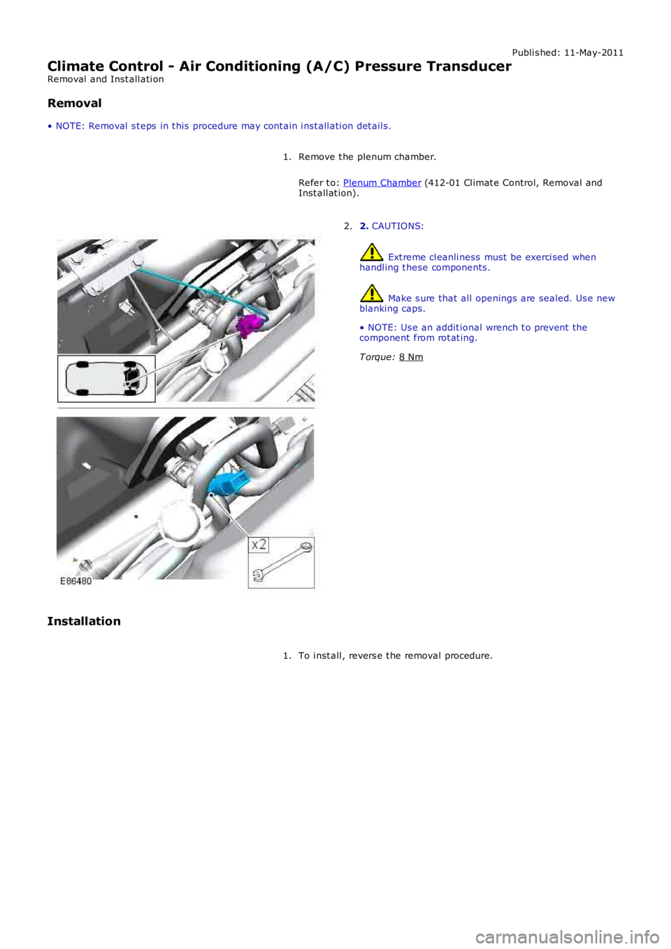
CAUTIONS: Ext reme cl eanli ness must be exerci sed when
handl ing t hese components . Make s ure that all openings are sealed. Us e new
blanking caps.
• NOTE: Us e an addit ional wrench t o prevent the
component from rot at ing.
T orque: 8 Nm 2.
Installation To i nst all , revers e t he removal procedure.
1.
Page 2560 of 3229

Publ is hed: 11-May-2011
Front End Sheet Metal Repairs - Fender Apron Panel
Removal and Installation
Removal
• NOTE: The fender apron panel is serviced as a separate weld-on panel. It is an assembly of the fender apron panel
reinforcement, fender apron lower panel and fender apron panel front extension.
• NOTE: The panel is serviced less its weld studs
1. The fender apron panel is replaced in conjunction with:
Front bumper cover
Hood lat ch panel
Both front fenders
Fender apron upper panel
2. Fo r a d d i t i o na l i nf o rma t i o n re l a t i ng t o t hi s re p a i r p ro ce d ure
please see the following:
Fo r a d d i t i o na l i nf o rma t i o n, re f e r t o : Body and Frame
(501-26
Body Repairs - Vehicle Specific Information and Tolerance
Checks, Description and Operation) /
St a nd a rd W o rks ho p P ra ct i ce s
(100-00 Ge ne ra l I nf o rma t i o n,
Description and Operation).
3. Remove the fender apron upper panel.
Fo r a d d i t i o na l i nf o rma t i o n, re f e r t o : Fender Apron Upper Panel
(501-27 Front End Sheet Met al Re pai rs , Removal and
Installation).
4. L H Si d e : Re mo ve t he a i r cl e a ne r.
Fo r a d d i t i o na l i nf o rma t i o n, re f e r t o : Air Cleaner
(303-12A
I nt a ke A i r Di s t ri b ut i o n a nd Fi l t e ri ng - I 6 3. 2L P e t ro l , Re mo va l
and Installation).
5. LH Side: Remove the air intake pipe.
6. LH Side: Remove the bat tery t ray.
Fo r a d d i t i o na l i nf o rma t i o n, re f e r t o : Battery Tray
(414-01
Battery, Mounting and Cables, Removal and Installation).
7. LH Side: Remove the engine lower support insulator.
Fo r a d d i t i o na l i nf o rma t i o n, re f e r t o : Engine Lower Support
Insulator (303-01A Engi ne - I6 3.2L Pet rol, Removal and
Installation).
8. LH Side: Release the battery junction box and position aside.
9. RH Side: Drain the cooling system.
Fo r a d d i t i o na l i nf o rma t i o n, re f e r t o : Cooling Sys tem Draining,
Filling and Bleeding (303-03A Engine Cooling - I6 3.2L Petrol,
General Procedures ).
10. RH Side: Evacuate the A/C system.
Fo r a d d i t i o na l i nf o rma t i o n, re f e r t o : Air Conditioning (A/C)
System Recovery, Evacuation and Charging (412-00 Cl i mat e
Co nt ro l Sys t e m - Ge ne ra l I nf o rma t i o n, Ge ne ra l P ro ce d ure s ).
11. RH Si d e : Re mo ve t he p o we r s t e e ri ng re s e rvo i r.
Fo r a d d i t i o na l i nf o rma t i o n, re f e r t o : P o we r St e e ri ng Fl ui d
Res ervoi r (211-02 Power St eeri ng, Removal and Ins t al lat i on).
12. RH Side: Release the coolant expansion tank and position
aside.
13. RH Side: Remove the engine mounting bracket.
Fo r a d d i t i o na l i nf o rma t i o n, re f e r t o : Engine Mount RH
(303-01A
Engine - I6 3.2L Petrol, Removal and Installation).
14. RH Side: Remove the windshield washer reservoir.
Fo r a d d i t i o na l i nf o rma t i o n, re f e r t o : Windshield Washer
Res ervoi r (501-16 W i pers and W as hers , Removal and
Installation).
15. RH Side: Remove the fender apron A/C pipes.
16. Remove the shock absorber and spring assembly.
Fo r a d d i t i o na l i nf o rma t i o n, re f e r t o : Sho ck A b s o rb e r a nd Sp ri ng
Assembly (204-01 Front Sus pens i on, Removal and
Installation).
17. Release and lay aside the wiring harness.
Page 2564 of 3229
Publ is hed: 11-May-2011
Front End Sheet Metal Repairs - Fender Apron Panel Reinforcement
Removal and Installation
Removal
• NOTE: The fender apron panel reinforcement has to be unpicked from the fender apron panel service panel, it is not
available separately.
• NOTE: The RH panel is serviced less its weld studs 1. T he f e nd e r a p ro n p a ne l re i nf o rce me nt i s re p l a ce d i n
conjunct ion wit h:
Front bumper cover
Hood lat ch panel
Both front fenders
Fender apron upper panel
2. Fo r a d d i t i o na l i nf o rma t i o n re l a t i ng t o t hi s re p a i r p ro ce d ure
please see the following:
Fo r a d d i t i o na l i nf o rma t i o n, re f e r t o : Body and Frame
(501-26
Body Repairs - Vehicle Specific Information and Tolerance
Checks, Description and Operation) /
St a nd a rd W o rks ho p P ra ct i ce s
(100-00 Ge ne ra l I nf o rma t i o n,
Description and Operation).
3. Remove the fender apron upper panel.
Fo r a d d i t i o na l i nf o rma t i o n, re f e r t o : Fender Apron Upper Panel
(501-27 Front End Sheet Met al Re pai rs , Removal and
Installation).
4. Remove the front shock absorber.
Fo r a d d i t i o na l i nf o rma t i o n, re f e r t o : Front Shock Abs orber
(204-01 Front Suspension, Removal and Installation).
5. LH Side: Remove the engine support insulator.
Fo r a d d i t i o na l i nf o rma t i o n, re f e r t o : Engine Upper Support
Insulator (303-01B Engi ne - TD4 2.2L Di es el, Removal and
Installation).
6. LH Side: Remove the bat tery t ray.
Fo r a d d i t i o na l i nf o rma t i o n, re f e r t o : Battery Tray
(414-01
Battery, Mounting and Cables, Removal and Installation).
7. LH Side: Remove the air intake pipe.
8. LH Side: Release the battery junction box and position aside.
9. RH Side: Remove the windshield washer reservoir.
Fo r a d d i t i o na l i nf o rma t i o n, re f e r t o : Windshield Washer
Res ervoi r (501-16 W i pers and W as hers , Removal and
Installation).
10. RH Side: Remove the engine mounting bracket.
Fo r a d d i t i o na l i nf o rma t i o n, re f e r t o : Engine Mount RH
(303-01B
Engine - TD4 2.2L Diesel, Removal and Installation).
11. RH Side: Release the coolant expansion tank and lay it
aside.
12. RH Side: Evacuate the A/C system.
Fo r a d d i t i o na l i nf o rma t i o n, re f e r t o : Air Conditioning (A/C)
System Recovery, Evacuation and Charging (412-00 Cl i mat e
Co nt ro l Sys t e m - Ge ne ra l I nf o rma t i o n, Ge ne ra l P ro ce d ure s ).
13. RH Side: Remove the fender apron A/C pipes.
14. RH Side: Release and lay aside the insulating material at the
bulkhead.
15. Release and lay aside the wiring harness.
Page 2731 of 3229
11
Quick start
R
Manual seat adjustment
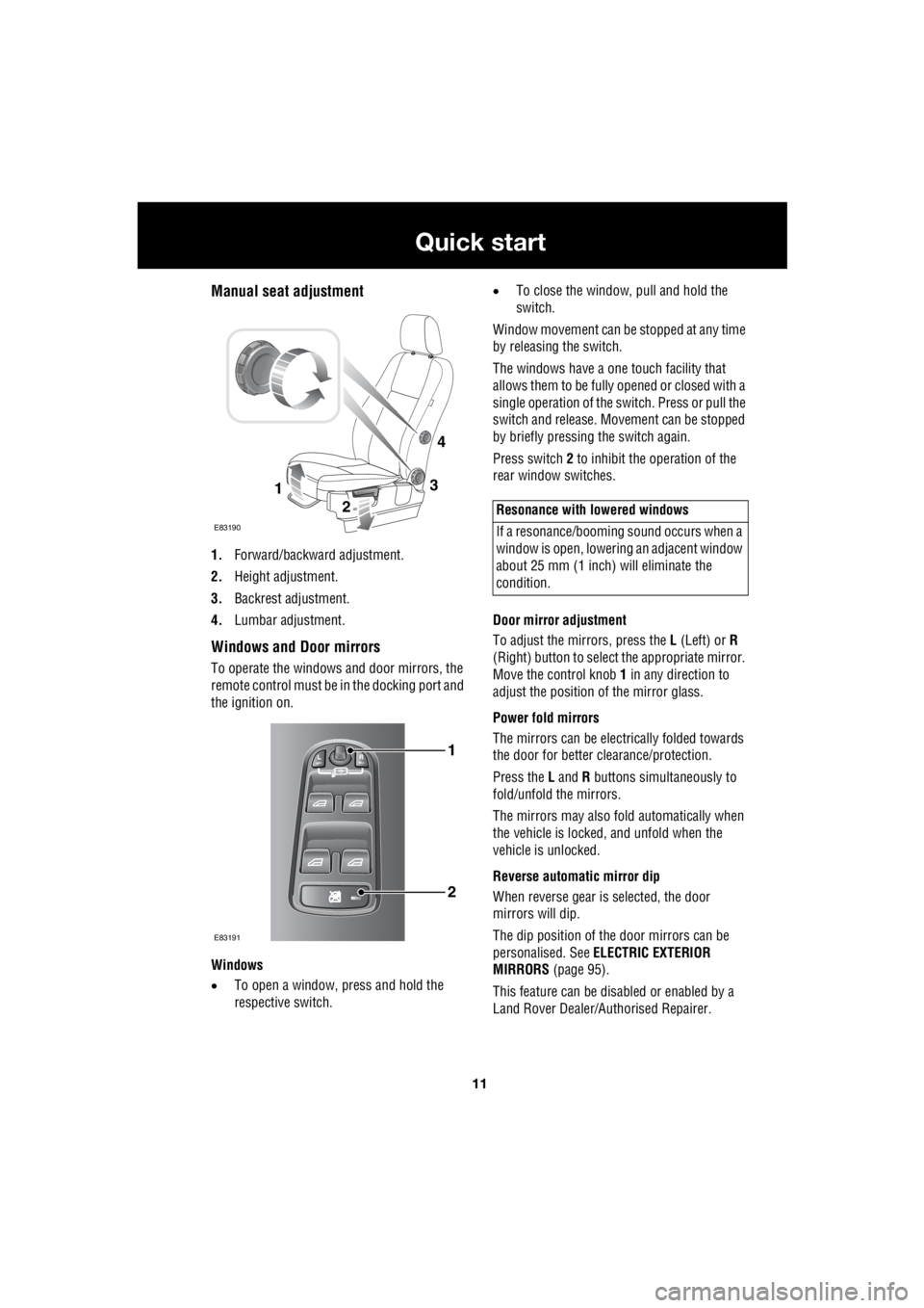
1. Forward/backward adjustment.
2. Height adjustment.
3. Backrest adjustment.
4. Lumbar adjustment.
Windows and Door mirrors
To operate the windows and door mirrors, the
remote control must be in the docking port and
the ignition on.
Windows
• To open a window, press and hold the
respective switch. •
To close the window, pull and hold the
switch.
Window movement can be stopped at any time
by releasing the switch.
The windows have a one touch facility that
allows them to be fully opened or closed with a
single operation of the switch. Press or pull the
switch and release. Mo vement can be stopped
by briefly pressing the switch again.
Press switch 2 to inhibit the operation of the
rear window switches.
Door mirror adjustment
To adjust the mirrors, press the L (Left) or R
(Right) button to select the appropriate mirror.
Move the control knob 1 in any direction to
adjust the position of the mirror glass.
Power fold mirrors
The mirrors can be electr ically folded towards
the door for better clearance/protection.
Press the L and R buttons simultaneously to
fold/unfold the mirrors.
The mirrors may also fold automatically when
the vehicle is locked, and unfold when the
vehicle is unlocked.
Reverse automatic mirror dip
When reverse gear is selected, the door
mirrors will dip.
The dip position of the door mirrors can be
personalised. See ELECTRIC EXTERIOR
MIRRORS (page 95).
This feature can be disabled or enabled by a
Land Rover Dealer/A uthorised Repairer.
3
2
1
E83190
4
1
2
E83191
Resonance with lowered windows
If a resonance/booming sound occurs when a
window is open, lowering an adjacent window
about 25 mm (1 inch) will eliminate the
condition.
Page 2734 of 3229
14
Quick start
L
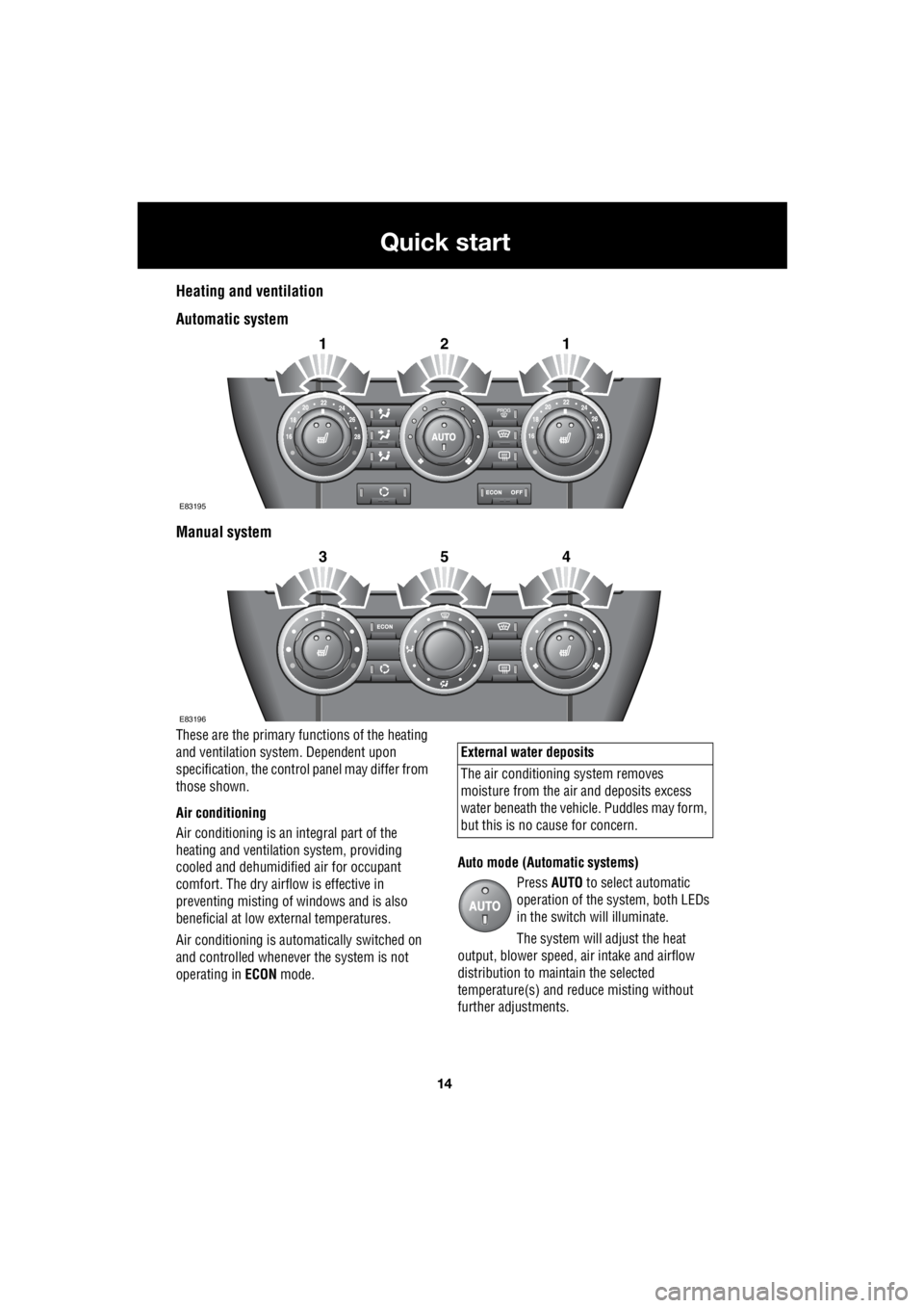
Heating and ventilation
Automatic system
Manual system
These are the primary functions of the heating
and ventilation syst em. Dependent upon
specification, the contro l panel may differ from
those shown.
Air conditioning
Air conditioning is an in tegral part of the
heating and ventilati on system, providing
cooled and dehumidifie d air for occupant
comfort. The dry airflow is effective in
preventing misting of windows and is also
beneficial at low external temperatures.
Air conditioning is automatically switched on
and controlled whenever the system is not
operating in ECON mode. Auto mode (Automatic systems)
Press AUTO to select automatic
operation of the system, both LEDs
in the switch will illuminate.
The system will adjust the heat
output, blower speed, air intake and airflow
distribution to maintain the selected
temperature(s) and re duce misting without
further adjustments.
2121
E83195
2354
E83196
External water deposits
The air conditioning system removes
moisture from the ai r and deposits excess
water beneath the vehicl e. Puddles may form,
but this is no cause for concern.
Page 2735 of 3229
15
Quick start
R
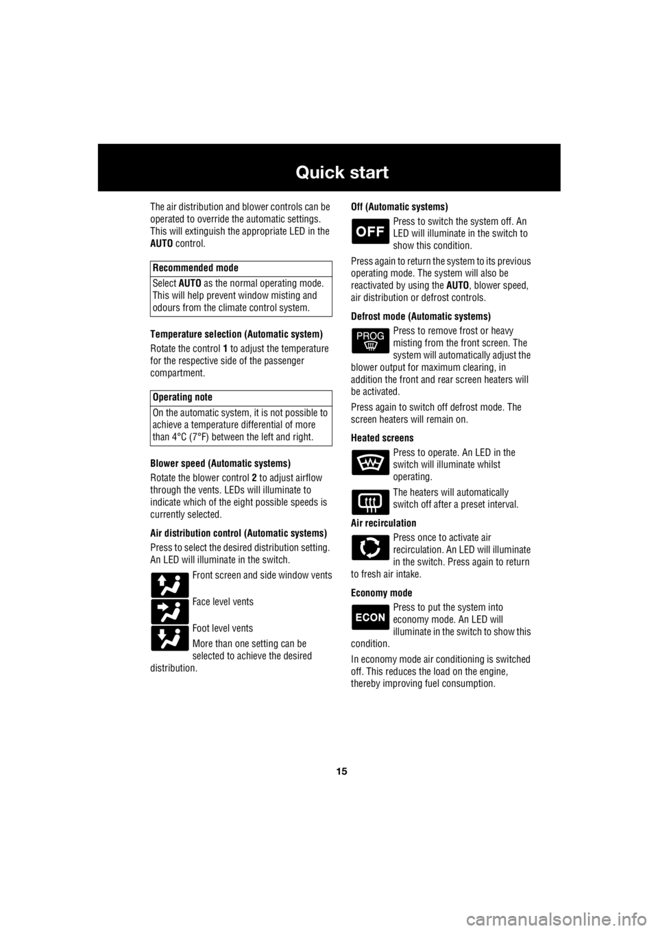
The air distribution and blower controls can be
operated to override the automatic settings.
This will extinguish the appropriate LED in the
AUTO control.
Temperature selection (Automatic system)
Rotate the control 1 to adjust the temperature
for the respective side of the passenger
compartment.
Blower speed (Automatic systems)
Rotate the blower control 2 to adjust airflow
through the vents. LEDs will illuminate to
indicate which of the ei ght possible speeds is
currently selected.
Air distribution contro l (Automatic systems)
Press to select the desi red distribution setting.
An LED will illumina te in the switch.
Front screen and side window vents
Face level vents
Foot level vents
More than one setting can be
selected to achieve the desired
distribution. Off (Automat
ic systems)
Press to switch the system off. An
LED will illuminate in the switch to
show this condition.
Press again to return the system to its previous
operating mode. The system will also be
reactivated by using the AUTO, blower speed,
air distribution or defrost controls.
Defrost mode (Automatic systems) Press to remove frost or heavy
misting from the front screen. The
system will automatically adjust the
blower output for maximum clearing, in
addition the front and rear screen heaters will
be activated.
Press again to switch off defrost mode. The
screen heaters will remain on.
Heated screens Press to operate. An LED in the
switch will illuminate whilst
operating.
The heaters will automatically
switch off after a preset interval.
Air recirculation Press once to activate air
recirculation. An LED will illuminate
in the switch. Press again to return
to fresh air intake.
Economy mode Press to put the system into
economy mode. An LED will
illuminate in the switch to show this
condition.
In economy mode air conditioning is switched
off. This reduces the load on the engine,
thereby improving fuel consumption.
Recommended mode
Select AUTO as the normal operating mode.
This will help prevent window misting and
odours from the climate control system.
Operating note
On the automatic system, it is not possible to
achieve a temperature differential of more
than 4°C (7°F) betwee n the left and right.
Page 2738 of 3229

18
Quick start
L
1. Exterior lamps master switch
2. Direction indicators/headlam ps/trip computer switch
3. Cruise control switches
4. Instrument pack
5. Audio/telephone switches
6. Washer/wiper switch
7. Start stop engine button
8. Master unlock switch
9. Hazard warning switch
10. Master lock switch
11. Audio unit
12. Heater/air conditioning controls
13. Dynamic Stability Control (DSC) switch
14. Gear selector
15. Touch screen
16. Parking brake
17. Terrain Response control switch
18. Hill Descent Control (HDC) switch
19. Starter control unit
20. Steering column adjustment lever
21. Horn switches
22. Facia illumination dimmer control