2006 LAND ROVER FRELANDER 2 light
[x] Cancel search: lightPage 2248 of 3229
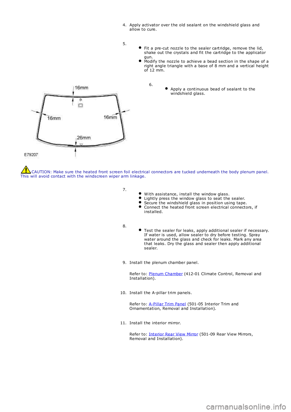
Apply acti vat or over t he old sealant on t he wi nds hiel d glas s andall ow t o cure.4.
Fit a pre-cut nozzl e t o the sealer cart ri dge, remove the lid,s hake out t he crys tal s and fi t the cartridge t o t he appl icatorgun.Modify t he nozzle to achieve a bead s ecti on in the s hape of aright angl e t ri angle wit h a bas e of 8 mm and a verti cal heightof 12 mm.
5.
Apply a cont inuous bead of s ealant to thewi nds hiel d glas s.
6.
CAUTION: Make s ure the heated front s creen foil electrical connect ors are t ucked underneat h t he body plenum panel.This wi ll avoid contact wit h t he winds creen wi per arm l inkage.
W it h ass i st ance, i ns t all the window glas s .Light ly pres s t he wi ndow glas s to seat t he s eal er.Secure t he winds hield gl ass in pos it ion us ing tape.Connect t he heat ed front s creen electrical connect ors , ifi ns t alled.
7.
Tes t the s ealer for l eaks , appl y addit ional s ealer i f necess ary.If water is used, all ow s eal er to dry before t es t ing. Spraywat er around the gl as s and check for leaks . Mark any areat hat l eaks . Dry the gl ass and sealer t hen appl y addit ionals ealer.
8.
Inst all t he plenum chamber panel.
Refer t o: Plenum Chamber (412-01 Cl imat e Control, Removal andInst all at ion).
9.
Inst all t he A-pi llar t ri m panels .
Refer t o: A-Pil lar Tri m Panel (501-05 Int erior Trim andOrnament ati on, Removal and Ins tal lat ion).
10.
Inst all t he int erior mi rror.
Refer t o: Int erior Rear View Mirror (501-09 Rear Vi ew Mi rrors ,Removal and Ins tall ati on).
11.
Page 2308 of 3229
OVERVIEW
Al l the vehi cle hinged panels are secured by lat ches with mating st rikers. The lat ches incorporat e panel ajar s wi tches t hatwi ll i nform the dri ver of an open acces s point .
The central locking s ys tem is operat ed by eit her t he remot e handset, front door central locking but tons or t he inst rumentpanel central locki ng s wi tches . The central locking s ys tem cont rols the automatic locking and unlocki ng of t he vehicl e ent rypoints. The soft ware used to cont rol t he cent ral l ocking syst em is i ncorporat ed within t he CJB.
The central locking s ys tem is al so integrat ed with t he interior l ighti ng functi on. The i nt eri or light s and exterior mirror lampsare i lluminated via t he RF recei ver and CJB following a val id unlock reques t from the remote hands et .For addit ional informat ion, refer t o: Interior Light ing (417-02 Interior Lighting, Des cri pt ion and Operation).
If configured by the deal er, the exterior door mirror power fold function is al so operat ed by the central locki ng s yst em.
A concealed mechanical door lock is provided in t he front LH door exteri or handle, and i s used to gain acces s to the vehicle ifthe battery is discharged or t he central l ocking syst em fail s.
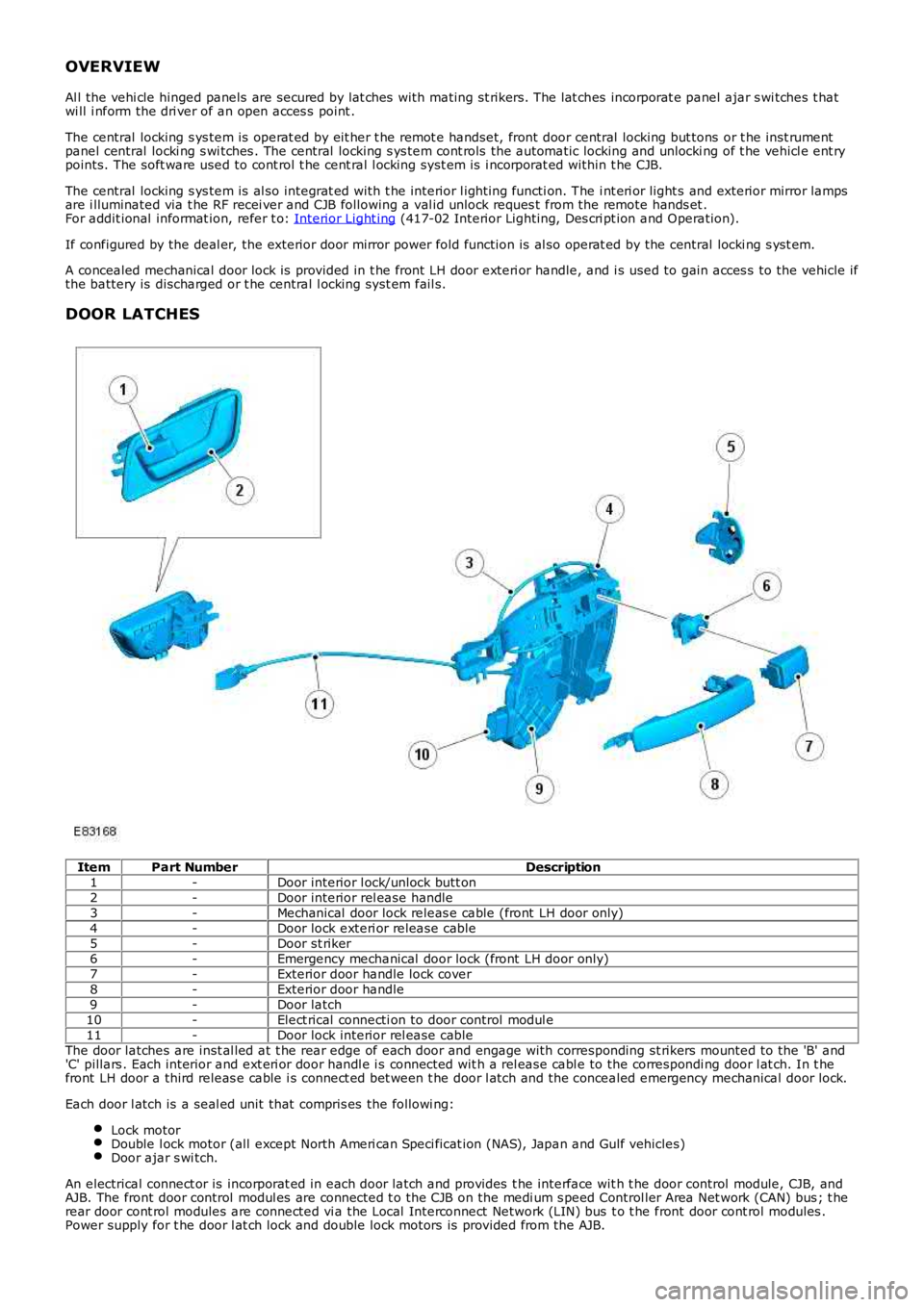
DOOR LATCHES
ItemPart NumberDescription1-Door interior l ock/unlock butt on2-Door interior rel ease handle3-Mechanical door lock releas e cable (front LH door only)4-Door lock exteri or release cable5-Door st riker6-Emergency mechanical door lock (front LH door only)7-Exterior door handle lock cover8-Exterior door handle9-Door latch10-Elect rical connecti on to door control modul e11-Door lock interior rel ease cableThe door latches are inst al led at t he rear edge of each door and engage with corresponding st rikers mounted to the 'B' and'C' pillars . Each interior and ext eri or door handl e i s connected wit h a rel ease cable to the correspondi ng door l at ch. In t hefront LH door a third releas e cable i s connect ed bet ween t he door l atch and the concealed emergency mechanical door lock.
Each door l atch is a seal ed unit that compris es the followi ng:
Lock motorDouble l ock motor (all except North Ameri can Speci ficat ion (NAS), Japan and Gulf vehicles)Door ajar s wi tch.
An electrical connect or is incorporat ed in each door latch and provides t he interface wit h t he door control module, CJB, andAJB. The front door control modul es are connected t o the CJB on the medi um s peed Control ler Area Net work (CAN) bus ; t herear door cont rol modules are connected vi a the Local Interconnect Network (LIN) bus t o t he front door cont rol modules .Power supply for t he door l at ch lock and double lock motors is provided from the AJB.
Page 2314 of 3229
RF Receiver
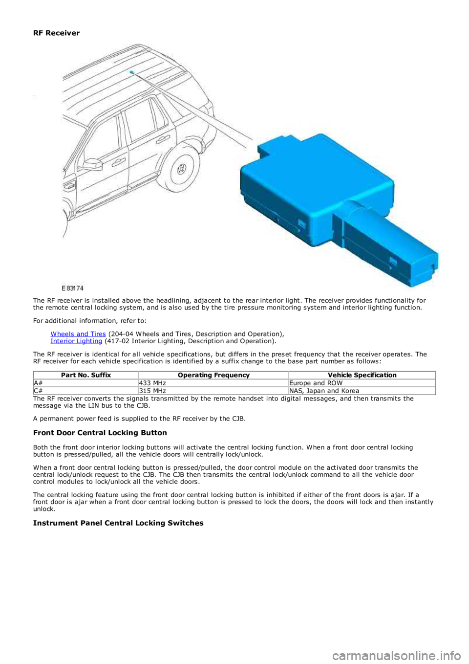
The RF receiver is inst all ed above the headlining, adjacent t o t he rear interi or light . The receiver provides functi onal ity forthe remote cent ral locking system, and i s als o us ed by t he t ire pres sure monit oring s ys tem and int erior li ghting function.
For addit ional informat ion, refer t o:
W heels and Tires (204-04 W heel s and Tires , Des cription and Operat ion),Interi or Lighting (417-02 Int erior Li ghting, Des cript ion and Operati on).
The RF receiver is identical for all vehi cle s peci ficati ons, but di ffers in the preset frequency that the recei ver operates. TheRF receiver for each vehi cle s pecificati on is identi fied by a suffi x change to t he bas e part number as fol lows :
Part No. SuffixOperating FrequencyVehicle Specification
A#433 MHzEurope and ROWC#315 MHzNAS, Japan and KoreaThe RF receiver converts the signals transmit ted by the remote hands et into digi tal mess ages , and t hen trans mits themess age vi a the LIN bus to t he CJB.
A permanent power feed is suppli ed to t he RF recei ver by the CJB.
Front Door Central Locking Button
Both the front door i nt erior locking but tons will acti vate the cent ral locking function. W hen a front door central l ockingbutton is pres sed/pulled, all the vehicle doors wil l centrall y l ock/unlock.
W hen a front door central l ocking butt on is press ed/pull ed, t he door control module on the act ivated door t ransmit s thecent ral lock/unlock request to t he CJB. The CJB then t rans mi ts the central lock/unlock command to all t he vehicl e doorcont rol modul es to l ock/unl ock all the vehi cle doors .
The central locking feature us ing the front door central l ocking butt on is inhi bi ted i f either of t he front doors i s ajar. If afront door i s ajar when a front door cent ral locking button is pres sed to lock the doors, the doors will lock and then i ns tantl yunlock.
Instrument Panel Central Locking Switches
Page 2348 of 3229
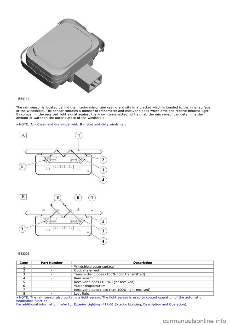
The rai n s ens or is locat ed behind t he int eri or mirror t rim casi ng and s it s in a bracket which is bonded t o t he inner surfaceof the windshi eld. The s ens or cont ains a number of transmit ter and receiver diodes which emi t and receive infrared li ght .By comparing the recei ved light s ignal agai ns t t he known transmit ted l ight s ignal, the rai n s ens or can det ermine t heamount of wat er on t he out er s urface of t he winds hield.
• NOTE: A = Clean and dry winds hield; B = W et and di rt y wi nds hiel d
ItemPart NumberDescription
1-W inds hield out er surface2-Opt ical element
3-Transmit ter diodes (100% li ght trans mi tt ed)
4-Rai n s ens or5-Receiver diodes (100% li ght recei ved)
6-W ater dropl et s /fil m
7-Receiver diodes (l ess than 100% light received)8-Los t li ght
• NOTE: The rai n s ensor als o contai ns a li ght sens or. The l ight sens or is us ed t o cont rol operat ion of t he aut omat icheadl amps functi on.For addit ional informat ion, refer t o: Ext eri or Li ght ing (417-01 Ext erior Light ing, Descri pti on and Operat ion).
Page 2352 of 3229
t o the 'Owners Handbook'.
Rear Screen Wiper
On recei vi ng a reques t for rear s creen wi per operat ion the CJB wi ll energize relay RA2 i n t he AJB. W hen energized, relayRA2 provides a feed t o t he rear s creen wiper mot or. The rear s creen wi per operat es int ermi tt entl y, wi th a delay betweenwipes of approximat ely 6 seconds . The CJB cont rol s operati on of rel ay RA2, and consequentl y rear s creen wiper mot oroperati on, accordingly.
The CJB als o provi des a feed t o t he rear s creen wi per mot or park s wit ch. The park s wit ch is i ntegral wi th the rear s creenwiper mot or and ens ures t he wi per returns to the park pos i ti on if t he rear wi per reques t is cancel led mid-st roke. The parks wit ch cont act s are cl osed when the rear wiper is i n any posi ti on except t he park pos it ion. Thi s all ows the CJB to returnt he rear wiper t o t he park pos it ion when relay RA2 i s de-energized.
The CJB wil l als o power the rear screen wiper motor i f revers e gear is s elected whi le the wi nds hiel d wi per funct ion i sact ive. On vehicles fit t ed wit h an aut omat ic trans mi s si on, t he reverse gear s ignal origi nat es in the Transmis si on ControlModule (TCM). The TCM broadcas ts a revers e gear s ignal over the hi gh s peed CAN bus to the CJB, which responds byoperati ng t he rear wiper.
On vehicles fit ted wit h a manual transmis s ion, the revers e gear s i gnal ori ginates at t he revers e gear s wit ch. The reversegear s wi tch i s hardwired t o t he CJB.
Windshield Washers
On recei vi ng a reques t for wi nds hiel d was her operat ion t he CJB wi ll energize t he front washer cont rol relay. Thi s all ows abatt ery volt age feed t o flow to the was her pump. A ground path for t he pump is provided by t he de-energized rear was hercont rol rel ay. Bot h was her control relays are int egral wit h t he CJB.
W hen wi ndshi el d was her operat ion i s reques ted, t he winds hi eld was hers will operat e. The CJB will delay wiper operati onfor 100 ms aft er the was her swi tch i s pres s ed. If t he s wit ch is pres s ed for l ess than 100 ms, t he CJB wil l not operat e t hewipers.
The CJB wil l power t he wi nds hield wipers for as l ong as washer operati on is reques t ed, al though t he washers wil l ti me outaft er 10 s econds. After t he was her s wi tch has been rel eas ed, the CJB wi ll operat e t he winds hi eld wipers t hrough 2 morewipe cycles .
Rear Screen Washer
On recei vi ng a reques t for rear s creen was her operati on the CJB wi ll energize the rear was her cont rol rel ay. This al lows abatt ery volt age feed t o flow to the was her pump. A ground path for t he pump is provided by t he de-energized front was hercont rol rel ay. Revers ing the polarit y of the pump (s ee 'W i nds hield W as hers ' above) allows was her fl uid t o be di rected t ot he rear s creen washer jet rather t han the windshi el d was her jets . The rear s creen was her jet is incorporat ed int o the hi ghmounted s t op lamp.
The rear s creen was her wi ll operat e for up t o 10 seconds if cont inuousl y reques ted. W hen rear s creen was her operati on isreques ted, the rear screen wiper wil l operat e conti nuous ly unt il t he s wit ch is released. After t he swit ch has been released,or fol lowing 10 seconds of conti nuous operat ion, the CJB will operat e t he rear s creen wiper t hrough 2 or 3 more wi pecycles .
Headlamp Washers
W hen t he vehicle ent ers i gni ti on mode 4 (acces s ory) to 7 (engine running) the firs t winds hield was h reques t great er than100 ms will operat e a headlamp power was h s equence. The CJB will t hen s tart a 10 mi nut e t imer. If 5 request s forwinds hield washer operati on are made wit hin this 10 mi nut e wi ndow, t he CJB wil l power t he headl amp was hers uponreceiving the fifth reques t . W hen t his occurs , the 10 minute ti mer is res et t o 0.
If the CJB receives no windshi el d was her reques t s duri ng a 10 mi nute window, the headlamp was hers will operat e on t hefi rs t reques t received aft er the 10 minut e window has el aps ed. Agai n, once t he headlamp was hers have been operati onal ,t he CJB res ets t he t imer t o 0.
The headl amp was hers wi ll only operat e when t he headl amps are on. The CJB receives a 'li ght s on' si gnal from the lightcont rol module over t he LIN bus .
W hen headlamp was her operati on is required, t he CJB energizes rel ay 9 in the BJB, all owing a bat tery vol tage feed t opower the headlamp was her pump. A ground path for t he washer pump i s provided by t he de-energi zed relay 12, which i sals o l ocat ed in the BJB. Thi s s equence of event s provides was her flui d t o the headlamp 1 was her jets .
Aft er thi s s equence the power s uppl y t o t he pump is revers ed. The CJB does t his by de-energi zing rel ay 9 and energi zi ngrel ay 12. Thi s allows the pump to provi de was her flui d to the headlamp 2 was her jets. The s equence of event s runs asfol lows :
Power to headlamp 1 was her - 500 msDelay t o power headl amp 2 was her - 100 msPower to headlamp 2 was her - 500 msDelay (s oak ti me) to power 1 headlamp washer - 700 msPower to 1 headl amp was her - 500 msDelay t o power 2 headl amp was her - 100 msPower to 2 headl amp was her - 500 ms
If there is l ess than 1 l it er (0.26 US gall on) of was her flui d in the was her fl uid reservoi r, t he CJB wil l s us pend headl ampwas her operat ion. The fl uid l evel s wit ch is hardwired to the CJB, which als o t rans mits a low fl ui d s ignal to the i nst rumentclus ter over t he medi um s peed CAN bus. For addit ional i nformati on, refer to:
Ins trument Clus ter (413-01 Ins t rument Clus t er, Descripti on and Operat ion),Informat ion and Mes s age Cent er (413-08 Informati on and Mes sage Cent er, Descripti on and Operat ion).
Page 2407 of 3229

3. CAUTION: Make s ure that the surface is cl ean and free of
foreign mat eri al.
Apply primer of t he correct s pecificati on t o the sealant face
on t he roof opening panel and al low t o cure. 3.
Inst all new rubber s pacers to the roof opening panel. 4.
Fit a pre-cut nozzl e t o the sealer cart ri dge, remove the lid,
s hake out t he crys tal s and fi t the cartridge t o t he appl icator
gun. 5.
Apply a cont inuous bead of s ealant to the body. Apply addit ional seal ant t o t he body fl anges .6.
W it h ass i st ance, i ns t all the roof openi ng panel as sembl y. Light ly pres s t he roof opening panel as s embly t o s eat the
s ealant. 7.
Connect t he drain tubes . 8.
Tes t the s ealant for l eaks , appl y addit ional s ealant if
neces s ary. If wat er is us ed, allow s eal ant t o dry before
t est ing. Spray wat er around the roof opening panel ass embly
and check for leaks. Mark any area t hat leaks. Dry t he
as sembl y and s eal ant then apply addit ional seal ant . 9.
Secure t he roof openi ng panel t ethers .
T orque: 4 Nm 10.
Inst all t he headl iner.
Refer t o: Headl iner - Vehi cl es W i th: Ti lt ing Roof Openi ng Panel (501-05 Int eri or Trim and Ornament ati on, Removal and Ins tal lati on).
11.
12. CAUTIONS: Make s ure that t he s urface i s clean and free of foreign
mat eri al .
12.
Page 2440 of 3229
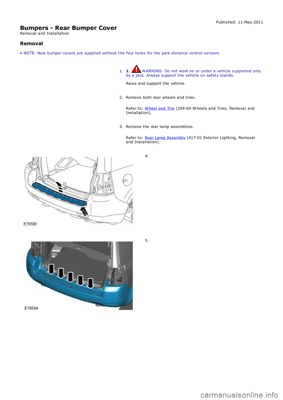
Publi s hed: 11-May-2011
Bumpers - Rear Bumper Cover
Removal and Inst all ati on
Removal
• NOTE: New bumper covers are suppli ed wit hout t he four holes for the park dis t ance control s ens ors .
1. W ARNING: Do not work on or under a vehi cle s upported onl yby a jack. Al ways support t he vehi cl e on s afet y s tands .
Rais e and s upport t he vehi cl e.
1.
Remove both rear wheel s and t ires .
Refer t o: W heel and Ti re (204-04 W heel s and Tires, Removal andInst all at ion).
2.
Remove t he rear lamp ass embli es.
Refer t o: Rear Lamp As s embly (417-01 Exterior Lighti ng, Removaland Inst all at ion).
3.
4.
5.
Page 2445 of 3229
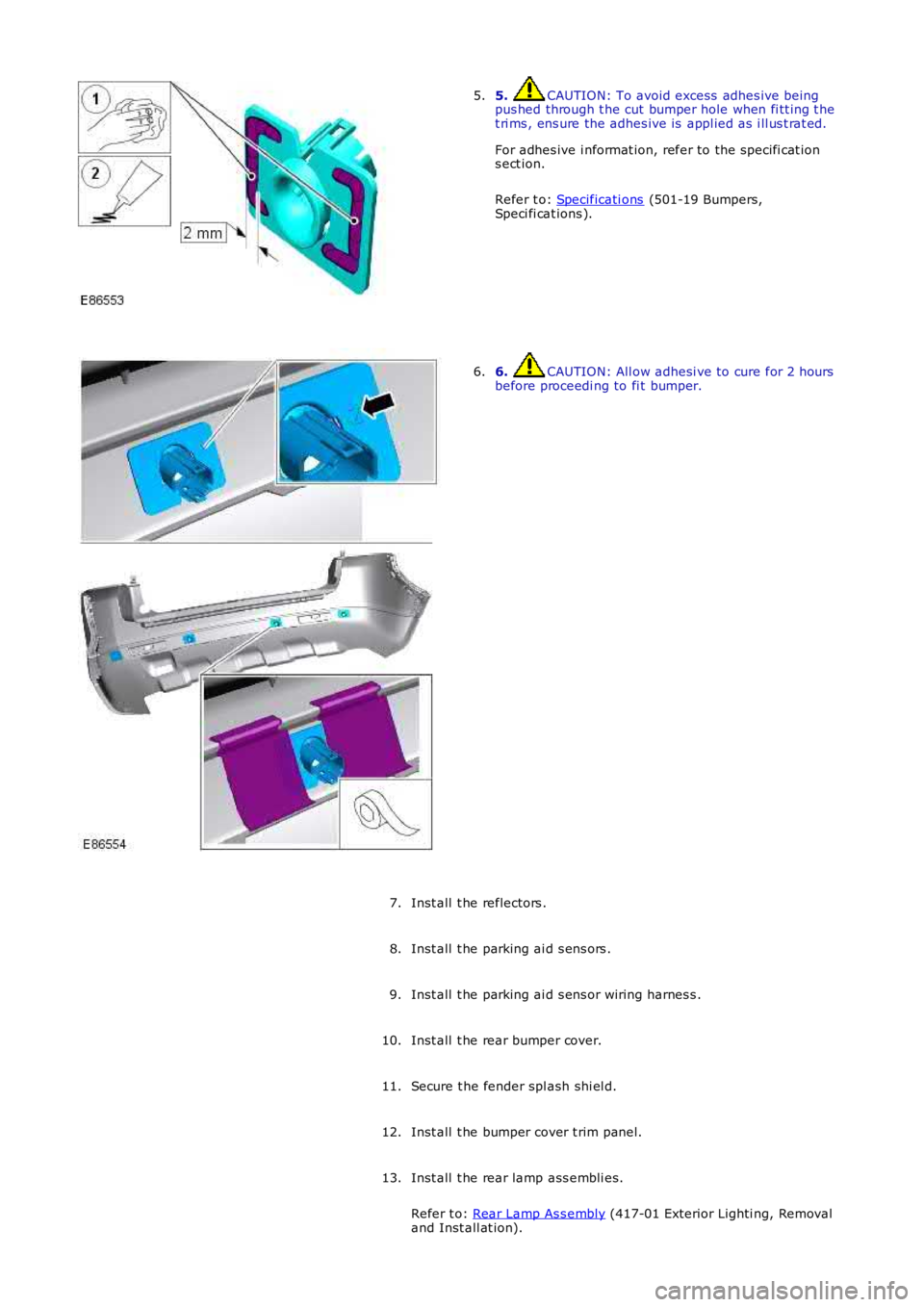
5. CAUTION: To avoid excess adhes ive beingpus hed through t he cut bumper hole when fi tt ing t het ri ms , ens ure the adhes ive is appl ied as i ll us t rat ed.
For adhes ive i nformat ion, refer to the s pecifi cat ions ect ion.
Refer t o: Specificati ons (501-19 Bumpers,Speci fi cat ions ).
5.
6. CAUTION: All ow adhesi ve to cure for 2 hoursbefore proceedi ng to fi t bumper.6.
Inst all t he reflectors .7.
Inst all t he parking ai d s ens ors .8.
Inst all t he parking ai d s ens or wiring harnes s .9.
Inst all t he rear bumper cover.10.
Secure t he fender spl ash shi el d.11.
Inst all t he bumper cover t rim panel.12.
Inst all t he rear lamp ass embli es.
Refer t o: Rear Lamp As s embly (417-01 Exterior Lighti ng, Removaland Inst all at ion).
13.