2006 DODGE RAM SRT-10 sensor
[x] Cancel search: sensorPage 2011 of 5267
MANIFOLD - INTAKE
REMOVAL
1. Disconnect the battery negative cables.
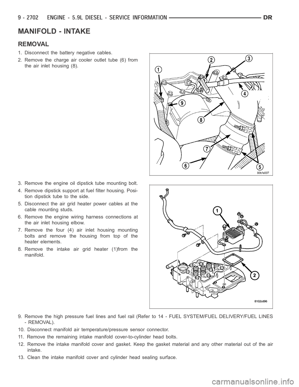
2. Remove the charge air cooler outlet tube (6) from
the air inlet housing (8).
3. Remove the engine oil dipstick tube mounting bolt.
4. Remove dipstick support at fuel filter housing. Posi-
tion dipstick tube to the side.
5. Disconnect the air grid heater power cables at the
cable mounting studs.
6. Remove the engine wiring harness connections at
the air inlet housing elbow.
7. Remove the four (4) air inlet housing mounting
bolts and remove the housing from top of the
heater elements.
8. Remove the intake air grid heater (1)from the
manifold.
9. Remove the high pressure fuel lines and fuel rail (Refer to 14 - FUEL SYSTEM/FUEL DELIVERY/FUEL LINES
- REMOVAL).
10. Disconnect manifold air temperature/pressure sensor connector.
11. Remove the remaining intake manifold cover-to-cylinder head bolts.
12. Remove the intake manifold cover and gasket. Keep the gasket material and any other material out of the air
intake.
13. Clean the intake manifold cover and cylinder head sealing surface.
Page 2012 of 5267
CLEANING
Clean manifold in solvent and blow dry with compressed air.
Clean cylinder block gasket surfaces using a suitable solvent.
The plenum pan rail must be clean and dry (free of all foreign material).
INSPECTION
Inspect manifold for cracks.
Inspect mating surfaces of manifold for flatness with a straightedge.
INSTALLATION
1. Using a new gasket, install the intake manifold cover.
2. Install the cover-to-cylinder head bolts that do not hold down the fuel rail.Tightentheboltsto24Nꞏm(18ft.lbs.)
torque.
3. Install the high pressure rail and fuel lines (Refer to 14 - FUEL SYSTEM/FUEL DELIVERY/FUEL LINES -
INSTALLATION).
4. Using two (2) new gaskets, install the intake air grid heater and air inlet housing.
5. Connect the manifold air temperature/pressure sensor connector.
6. Install and tighten the air intake heater power supply nut to 14 Nꞏm (120 in. lbs.) torque.
7. Install oil dipstick tube support at fuel filter housing.
8. Install the engine oil dipstick tube and mounting bolt.
9. Position the charge air cooler outlet tube onto the air inlet housing. Tightentheclampsto11Nꞏm(100in.lbs.)
torque.
10. Attach the engine wire harness to the air inlet housing.
11. Prime the fuel system. Refer to the fuel priming procedure in Group 14, Fuel System.
12. Connect the battery negative cables.
Page 2016 of 5267
CASE - FRONT
REMOVAL
1. Disconnect the battery negative cables.
2. Raise vehicle on hoist.
3. Partially drain engine coolant into container suitable for re-use (Refer to 7 - COOLING - STANDARD PROCE-
DURE).
4. Lower vehicle.
5. Remove radiator upper hose.
6. Disconnect coolant recovery bottle hose from radiator filler neck.
7. Remove viscous fan/drive/shroud assembly (Refer to 7 - COOLING/ENGINE/RADIATOR FAN - REMOVAL).
8. Remove the accessory drive belt (Refer to 7 - COOLING/ACCESSORY DRIVE/DRIVE BELTS - REMOVAL).
9. Remove the cooling fan support/hub from the front of the engine.
10. Raisethevehicleonhoist.
11. Remove the crankshaft damper (Refer to 9 - ENGINE/ENGINE BLOCK/VIBRATION DAMPER - REMOVAL) and
speed indicator ring.
12. Remove the lower fan shroud bracket.
13. Remove the upper fan shroud bracket that is mounted to the gear housing.
14. Lower the vehicle.
15. Remove the power steering pump.
16. Remove the accessory drive belt tensioner.
17. Remove the gear cover-to-housing bolts and gently pry the cover away from the housing, taking care not to mar
the gasket surfaces.
18. Remove the fuel injection pump (Refer to 14 - FUEL SYSTEM/FUEL DELIVERY/FUEL INJECTION PUMP -
REMOVAL).
19. Disconnect the camshaft position sensor connector.
20. Disconnect and remove engine speed sensor.
21. Remove the camshaft (Refer to 9 - ENGINE/ENGINE BLOCK/CAMSHAFT & BEARINGS (IN BLOCK) -
REMOVAL).
22. Remove the six front oil pan fasteners.
23. Remove the gear housing fasteners.
NOTE: Use care when removing the gear housing, to avoid damage to the oil pangasket, as the gasket will
be reused if it is not damaged.
24. Slide a feeler gauge between the gear housing and oil pan gasket, to break the gasket seal.
25. Remove the gear housing and gasket.
26. Clean the gasket material from the cylinder block and gear housing.
Page 2017 of 5267
INSTALLATION
1.Inspectoilpangasket.Iftorn,gasketmustbe
replaced.
2. Install a new gear housing gasket onto cylinder
block and trim any excesss gasket material flush to
oil pan rail.
3. Place a small amount of mopar
engine RTV to the
corners of the block and pan gasket T-joint to
ensure a good seal.
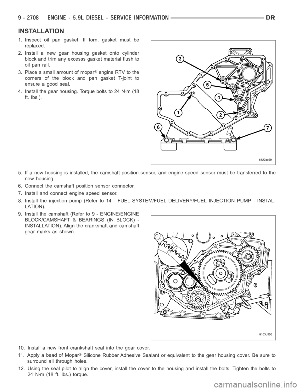
4. Install the gear housing. Torque bolts to 24 Nꞏm (18
ft. lbs.).
5. If a new housing is installed, the camshaft position sensor, and engine speed sensor must be transferred to the
new housing.
6. Connect the camshaft position sensor connector.
7. Install and connect engine speed sensor.
8. Install the injection pump (Refer to 14 - FUEL SYSTEM/FUEL DELIVERY/FUEL INJECTION PUMP - INSTAL-
LATION).
9. Install the camshaft (Refer to 9 - ENGINE/ENGINE
BLOCK/CAMSHAFT & BEARINGS (IN BLOCK) -
INSTALLATION). Align the crankshaft and camshaft
gear marks as shown.
10. Install a new front crankshaft seal into the gear cover.
11. Apply a bead of Mopar
Silicone Rubber Adhesive Sealant or equivalent to the gear housing cover.Be sure to
surround all through holes.
12. Using the seal pilot to align the cover, install the cover to the housingand install the bolts. Tighten the bolts to
24 Nꞏm (18 ft. lbs.) torque.
Page 2021 of 5267
INSPECTION ............................... 2789
ASSEMBLY . ............................... 2791
INSTALLATION ............................. 2792
SENSOR-OIL PRESSURE
REMOVAL ................................. 2793
INSTALLATION ............................. 2793
SENSOR-OIL TEMPERATURE
REMOVAL ................................. 2794
INSTALLATION ............................. 2794
BLOCK-ENGINE
DESCRIPTION ............................. 2795
STANDARD PROCEDURE - CYLINDER BORE
HONING ................................. 2795
CLEANING ................................. 2795
INSPECTION ............................... 2796
HYDRAULIC TAPPETS
DESCRIPTION ............................. 2797
REMOVAL ................................. 2797
INSTALLATION ............................. 2798
CAMSHAFT
REMOVAL ................................. 2799
INSTALLATION ............................. 2800
ROD-PISTON & CONNECTING
DESCRIPTION ............................. 2802
STANDARD PROCEDURE
PISTON FITTING ......................... 2802
MEASURING CONNECTING ROD SIDE
CLEARANCE............................. 2803
REMOVAL ................................. 2803
INSPECTION ............................... 2804
INSTALLATION ............................. 2805
RINGS-PISTON
STANDARD PROCEDURE - MEASURING
PISTON RING CLEARANCES .............. 2807REMOVAL ................................. 2807
INSTALLATION ............................. 2808
BEARINGS-CONNECTING ROD
DESCRIPTION ............................. 2810
STANDARD PROCEDURE
CONNECTING ROD BEARING - FITTING . . . 2810
MEASURING CONNECTING ROD BEARING
CLEARANCE............................. 2810
DAMPER-CRANKSHAFT
REMOVAL ................................. 2812
INSTALLATION ............................. 2813
SEAL-CRANKSHAFT OIL- FRONT
REMOVAL ................................. 2814
INSTALLATION ............................. 2814
SEAL-OIL-REAR-CRANK AND RETAINER
REMOVAL ................................. 2815
INSTALLATION ............................. 2815
BEARINGS-CRANKSHAFT MAIN
DESCRIPTION ............................. 2817
STANDARD PROCEDURE
MEASURING CRANKSHAFT MAIN BEARING
CLEARANCE IN-CAR...................... 2817
CRANKSHAFT
STANDARD PROCEDURE
MEASURING CRANKSHAFT END PLAY .... 2819
CRANKSHAFT JOURNAL MEASUREMENT . 2819
REMOVAL ................................. 2820
INSPECTION............................... 2822
INSTALLATION ............................. 2822
BEARING-CRANKSHAFT PILOT
REMOVAL ................................. 2825
INSTALLATION ............................. 2825
Page 2023 of 5267
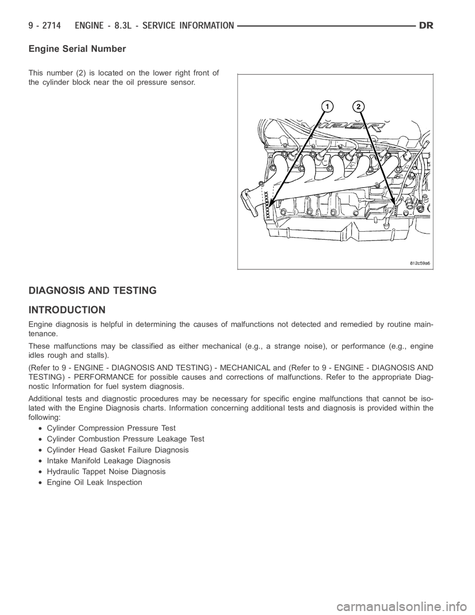
Engine Serial Number
This number (2) is located on the lower right front of
the cylinder block near the oil pressure sensor.
DIAGNOSIS AND TESTING
INTRODUCTION
Engine diagnosis is helpful in determining the causes of malfunctions notdetected and remedied by routine main-
tenance.
These malfunctions may be classified as either mechanical (e.g., a strange noise), or performance (e.g., engine
idles rough and stalls).
(Refer to 9 - ENGINE - DIAGNOSIS AND TESTING) - MECHANICAL and (Refer to 9 - ENGINE - DIAGNOSIS AND
TESTING) - PERFORMANCE for possible causes and corrections of malfunctions. Refer to the appropriate Diag-
nostic Information for fuel system diagnosis.
Additional tests and diagnostic procedures may be necessary for specificengine malfunctions that cannot be iso-
lated with the Engine Diagnosis charts. Information concerning additional tests and diagnosis is provided within the
following:
Cylinder Compression Pressure Test
Cylinder Combustion Pressure Leakage Test
Cylinder Head Gasket Failure Diagnosis
Intake Manifold Leakage Diagnosis
Hydraulic Tappet Noise Diagnosis
Engine Oil Leak Inspection
Page 2029 of 5267
CHEMICAL TEST METHOD
Combustion leaks into the cooling system can also be checked by using Bloc-Chek Kit C-3685-A or equivalent.
Perform test following the procedures supplied with the tool kit.
HYDRAULIC TAPPET NOISE DIAGNOSIS
PRELIMINARY STEP TO CHECKING THE HYDRAULIC TAPPETS
Before disassembling any part of the engine to correct tappet noise, checkengine oil level and oil pressure.
1. Check the engine oil level.
Oil Level Check: stop engine after reaching normal operating temperature
The oil level should never be above the FULL mark on dipstick, or below the ADD mark. Either of
these two conditions could be responsible for noisy tappets. Allow 5 minutes to stabilize oil level,
check dipstick.
2. Remove oil pressure sensor.
3. Install a reliable oil pressure gauge at oil pressure sensor location.
The oil pressure should be 206.8 - 551.6 kPa (30 - 80 psi) at 2000 rpm.
OIL LEVEL TOO HIGH
If oil level is above the FULL mark on dipstick, it is possible for the connecting rods to dip into the oil while engine
is running and create foam. Foam in oil pan would be fed to the hydraulic tappets by the oil pump causing them to
become soft and allow valves to seat noisily.
OIL LEVEL TOO LOW
Low oil level may allow pump to take in air which when fed to the tappets, causes them to become soft and allows
valves to seat noisily. Any leaks on intake side of pump through which air canbedrawnwillcreatethesametappet
action. Check the lubrication system from the intake strainer to the pump cover, including the relief valve retainer
cap. When tappet noise is due to aeration, it may be intermittent or constant, and usually more than one tappet will
be noisy. When oil level and leaks have been corrected, engine should be operated at fast idle to allow all of the air
inside of the tappets to be bled out.
VALVE TRAIN NOISE DIAGNOSIS
To determine source of valve train noise, operate engine at idle with cylinder head covers removed and listen for
source of the noise.
NOTE: Worn valve guides or cocked springs are sometimes mistaken for noisytappets. If such is the case,
noise may be dampened by applying side thrust on the valve spring. If noise is not appreciably reduced, it
can be assumed the noise is in the tappet. Inspect the rocker arm push rod sockets and push rod ends for
wear.
Valve tappet noise ranges from light noise to a heavy click. A light noise isusually caused by excessive leak-down
around the unit plunger which will necessitate replacing the tappet, or bythe plunger partially sticking in the tappet
body cylinder. A heavy click is caused either by a tappet check valve not seating, or by foreign particles becoming
wedged between the plunger and the tappet body causing the plunger to stickin the down position. This heavy click
will be accompanied by excessive clearance between the valve stem and rocker arm as valve closes. In either case,
tappet assembly should be removed and replaced.
ENGINE OIL LEAK INSPECTION
Begin with a thorough visual inspection of the engine, particularly at thearea of the suspected leak. If an oil leak
source is not readily identifiable, thefollowingstepsshouldbefollowed:
1. Do not clean or degrease the engine at this time because some solvents maycause rubber to swell, temporarily
stopping the leak.
2. Add an oil soluble dye (use as recommended by manufacturer). Start the engine and let idle for approximately 15
minutes. Check the oil dipstick to make sure the dye is thoroughly mixed as indicated with a bright yellow color
under a black light.
Page 2040 of 5267
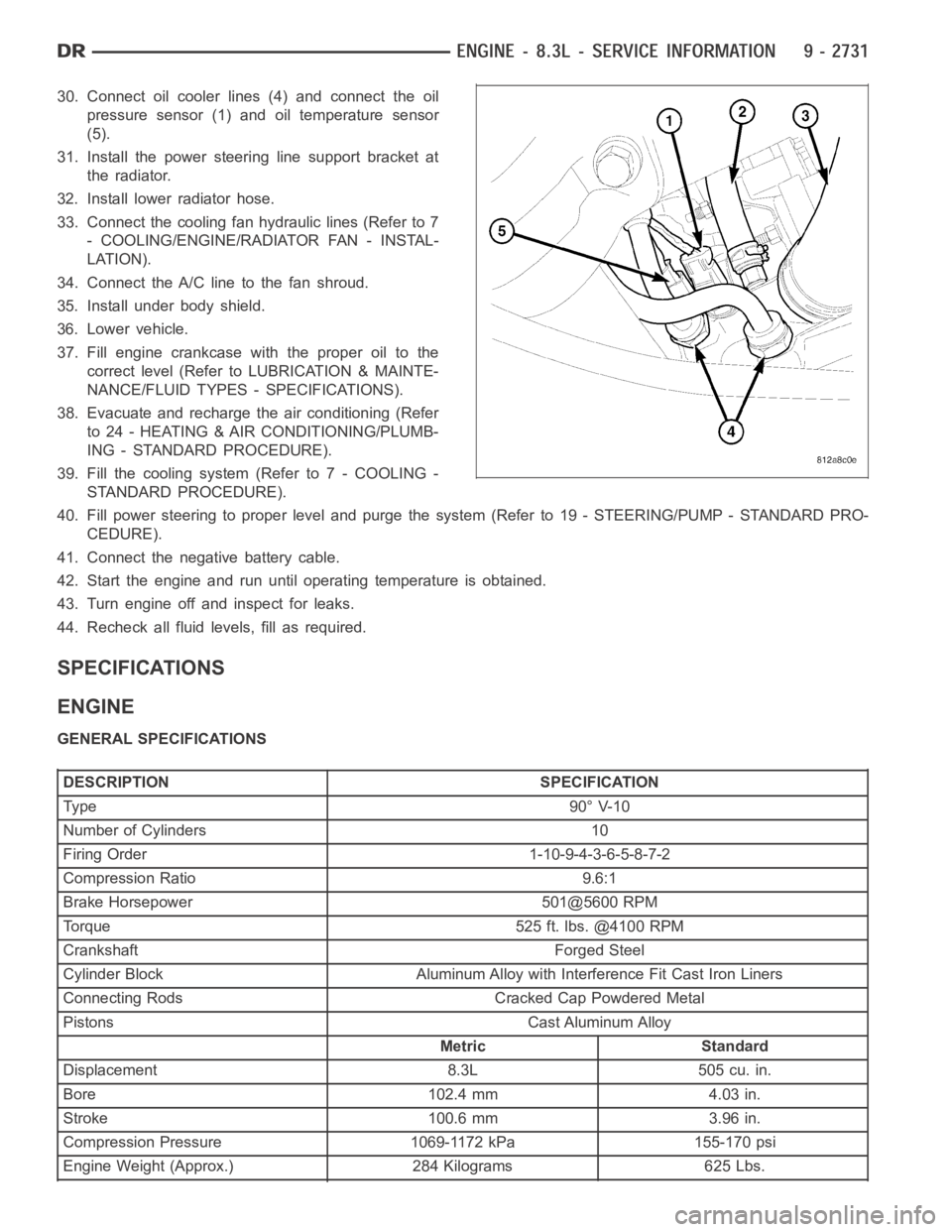
30. Connect oil cooler lines (4) and connect the oil
pressure sensor (1) and oil temperature sensor
(5).
31. Install the power steering line support bracket at
the radiator.
32. Install lower radiator hose.
33. Connect the cooling fan hydraulic lines (Refer to 7
- COOLING/ENGINE/RADIATOR FAN - INSTAL-
LATION).
34. Connect the A/C line to the fan shroud.
35. Install under body shield.
36. Lower vehicle.
37. Fill engine crankcase with the proper oil to the
correct level (Refer to LUBRICATION & MAINTE-
NANCE/FLUID TYPES - SPECIFICATIONS).
38. Evacuate and recharge the air conditioning (Refer
to 24 - HEATING & AIR CONDITIONING/PLUMB-
ING - STANDARD PROCEDURE).
39. Fill the cooling system (Refer to 7 - COOLING -
STANDARD PROCEDURE).
40. Fill power steering to proper leveland purge the system (Refer to 19 - STEERING/PUMP - STANDARD PRO-
CEDURE).
41. Connect the negative battery cable.
42. Start the engine and run until operating temperature is obtained.
43. Turn engine off and inspect for leaks.
44. Recheck all fluid levels, fill as required.
SPECIFICATIONS
ENGINE
GENERAL SPECIFICATIONS
DESCRIPTION SPECIFICATION
Ty pe 9 0° V-1 0
Number of Cylinders 10
Firing Order 1-10-9-4-3-6-5-8-7-2
Compression Ratio 9.6:1
Brake Horsepower 501@5600 RPM
Torque 525 ft. lbs. @4100 RPM
Crankshaft Forged Steel
Cylinder Block Aluminum Alloy with Interference Fit Cast Iron Liners
Connecting Rods Cracked Cap Powdered Metal
Pistons Cast Aluminum Alloy
Metric Standard
Displacement 8.3L 505 cu. in.
Bore 102.4 mm 4.03 in.
Stroke 100.6 mm 3.96 in.
Compression Pressure 1069-1172 kPa 155-170 psi
Engine Weight (Approx.) 284 Kilograms 625 Lbs.