Page 1631 of 5267
9. Disconnect crankshaft position sensor (1).
NOTE: The following step applies to 4X4vehicles equipped with automatic transmission only.
10.4X4 vehiclesRemove the axle isolator bracket from the engine, transmission and the axle.
11. Remove structural cover (Refer to 9 - ENGINE/
ENGINE BLOCK/STRUCTURAL COVER -
REMOVAL).
12. Remove starter (4) (Refer to 8 - ELECTRICAL/
STARTING/STARTER MOTOR - REMOVAL).
Page 1634 of 5267

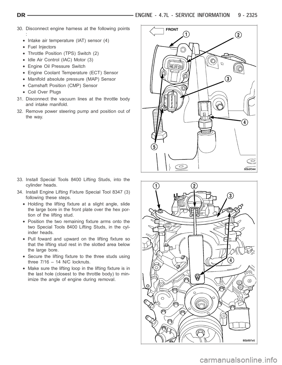
30. Disconnect engine harness at the following points
:
Intake air temperature (IAT) sensor (4)
Fuel Injectors
Throttle Position (TPS) Switch (2)
Idle Air Control (IAC) Motor (3)
Engine Oil Pressure Switch
Engine Coolant Temperature (ECT) Sensor
Manifold absolute pressure (MAP) Sensor
Camshaft Position (CMP) Sensor
Coil Over Plugs
31. Disconnect the vacuum lines at the throttle body
and intake manifold.
32. Remove power steering pump and position out of
the way.
33. Install Special Tools 8400 Lifting Studs, into the
cylinder heads.
34. Install Engine Lifting Fixture Special Tool 8347 (3)
following these steps.
Holding the lifting fixture at a slight angle, slide
the large bore in the front plate over the hex por-
tion of the lifting stud.
Position the two remaining fixture arms onto the
two Special Tools 8400 Lifting Studs, in the cyl-
inder heads.
Pull foward and upward on the lifting fixture so
that the lifting stud rest in the slotted area below
the large bore.
Secure the lifting fixture to the three studs using
three 7/16 – 14 N/C locknuts.
Make sure the lifting loop in the lifting fixture is in
the last hole (closest to the throttle body) to min-
imize the angle of engine during removal.
Page 1637 of 5267
6. Position generator wiring behind the oil dipstick
tube, then install the oil dipstick tube upper mount-
ing bolt.
7. Connect both left (2) and right (3) side body ground
straps.
8. Install power steering pump.
9. Connect fuel supply line quick connect fitting (Refer
to 14 - FUEL SYSTEM/FUEL DELIVERY/QUICK
CONNECT FITTING - STANDARD PROCEDURE).
10. Connect the vacuum lines at the throttle body and
intake manifold.
11. Connect engine harness at the following points :
Intake Air Temperature (IAT) Sensor (4)
Idle Air Control (IAC) Motor (3)
Fuel Injectors
Throttle Position (TPS) Switch (2)
Engine Oil Pressure Switch
Engine Coolant Temperature (ECT) Sensor
Manifold Absolute Pressure (MAP) Sensor
Camshaft Position (CMP) Sensor
Coil Over Plugs
Page 1639 of 5267
19. Install A/C compressor (2) (Refer to 24 - HEAT-
ING & AIR CONDITIONING/PLUMBING/A/C
COMPRESSOR - INSTALLATION).
20. Install both breathers (1). Connect tube to both
crankcase breathers.
21. Connect throttle and speed control cables.
22. Install throttle body resonator assembly and air
inlet hose. Tighten clamps 4 Nꞏm (35 in. lbs.).
23. Raise vehicle.
24. Install transmission to engine mounting bolts.
Tighten the bolts to 41 Nꞏm (30 ft. lbs.).
25. Install torque converter bolts (Automatic Transmis-
sion Only).
26. Connect crankshaft position sensor (1).
27.4X4 vehiclesPosition and install the axle isolator
bracket onto the axle, transmission and engine
block. Tighten bolts to specification (Refer to 9 -
ENGINE - SPECIFICATIONS).
Page 1673 of 5267
6. Remove the camshaft position sensor (1).
NOTE: When gripping the camshaft, place the pli-
ers (1) on the tube portion of the camshaft only.
Do not grip the lobes or the sprocket areas.
7. Hold the camshaft with adjustable pliers (1) while
removing the camshaft sprocket bolt (2)and
sprocket (3).
8. Using the pliers (1), gently allow the camshaft to
rotate 45° counter-clockwise until the camshaft is in
the neutral position (no valve load).
Page 1677 of 5267
11. Install the camshaft position sensor.
12. Install the cylinder head cover (1) (Refer to 9 -
ENGINE/CYLINDER HEAD/CYLINDER HEAD
COVER(S) - INSTALLATION).
Page 1694 of 5267

CRANKSHAFT
DESCRIPTION
The crankshaft is constructed of nodular cast iron. The crankshaft is a crosshaped four throw design with eight
counterweights for balancing purposes. The crankshaft is supported by five select fit main bearings with the number
three serving as the thrust washer location. The main journals of the crankshaft are cross drilled to improve rod
bearing lubrication. The number eight counterweight has provisions for crankshaft position sensor target wheel
mounting. The select fit main bearing markings are located on the rear sideof the target wheel. The crankshaft oil
seals are one piece design. The front oil seal is retained in the timing chain cover, and the rear seal is pressed in
to a bore formed by the cylinder block and the bedplate assembly.
REMOVAL
NOTE: To remove the crankshaft from the engine, the engine must be removed from the vehicle.
1. Remove the engine. (Refer to 9 - ENGINE - REMOVAL).
2. Remove the engine oil pump. (Refer to 9 - ENGINE/LUBRICATION/OIL PUMP - REMOVAL).
CAUTION: DO NOT pry on the oil pan gasket when removing the oil pan, The oil pan gasket is mounted to
the cylinder block in three locations and will remain attached to block when removing oil pan. Gasket can
not be removed with oil pan.
3. Remove oil pan. (Refer to 9 - ENGINE/LUBRICATION/OIL PAN - REMOVAL).
4. Remove the oil pump pickup tube and oil pan gasket /windage tray.
5. Remove the bedplate mounting bolts. Note the location of the three stud bolts for installation.
6. Remove the connecting rods from the crankshaft.
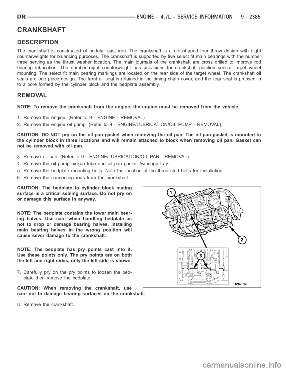
CAUTION: The bedplate to cylinder block mating
surface is a critical sealing surface. Do not pry on
or damage this surface in anyway.
NOTE: The bedplate contains the lower main bear-
ing halves. Use care when handling bedplate as
not to drop or damage bearing halves. Installing
main bearing halves in the wrong position will
cause sever damage to the crankshaft.
NOTE: The bedplate has pry points cast into it.
Use these points only. The pry points are on both
the left and right sides, only the left side is shown.
7. Carefully pry on the pry points to loosen the bed-
plate then remove the bedplate.
CAUTION: When removing the crankshaft, use
care not to damage bearing surfaces on the crankshaft.
8. Remove the crankshaft.
Page 1698 of 5267

BEARINGS - CRANKSHAFT MAIN
STANDARD PROCEDURE - CRANKSHAFT MAIN BEARING - FITTING
MAIN BEARING JOURNAL DIAMETER (CRANKSHAFT REMOVED)
Crankshaft removed from the cylinder block.
Clean the oil off the main bearing journal.
Determine the maximum diameter of the journal with a micrometer. Measure at two locations 90° apart at each end
of the journal.
The maximum allowable taper is 0.008mm (0.0004 inch.) and maximum out of round is 0.005mm (0.002 inch). Com-
pare the measured diameter with the journal diameter specification (MainBearing Fitting Chart). Select inserts
required to obtain the specified bearing-to-journal clearance.
CRANKSHAFT MAIN BEARING SELECTION
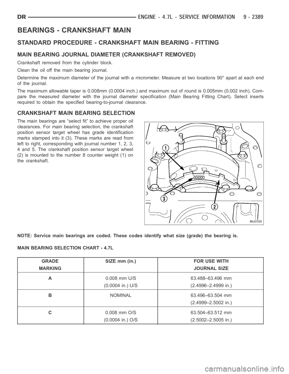
The main bearings are “select fit” to achieve proper oil
clearances. For main bearing selection, the crankshaft
position sensor target wheel has grade identification
marks stamped into it (3). These marks are read from
left to right, corresponding with journal number 1, 2, 3,
4 and 5. The crankshaft position sensor target wheel
(2) is mounted to the number 8 counter weight (1) on
the crankshaft.
NOTE: Service main bearings are coded. These codes identify what size (grade) the bearing is.
MAIN BEARING SELECTION CHART - 4.7L
GRADE SIZE mm (in.) FOR USE WITH
MARKING JOURNAL SIZE
A0.008 mm U/S 63.488–63.496 mm
(0.0004 in.) U/S (2.4996–2.4999 in.)
BNOMINAL 63.496–63.504 mm
(2.4999–2.5002 in.)
C0.008 mm O/S 63.504–63.512 mm
(0.0004 in.) O/S (2.5002–2.5005 in.)