Page 1490 of 5267
(Refer to 9 - ENGINE - DIAGNOSIS AND TESTING) - PERFORMANCE and (Refer to 9 - ENGINE - DIAGNOSIS
AND TESTING)—MECHANICAL for possible causes and corrections of malfunctions. (Refer to 14 - FUEL SYSTEM/
FUEL DELIVERY - DIAGNOSIS AND TESTING) and (Refer to 14 - FUEL SYSTEM/FUEL INJECTION - DIAGNO-
SIS AND TESTING) for the fuel system diagnosis.
Additional tests and diagnostic procedures may be necessary for specificengine malfunctions that can not be iso-
lated with the Service Diagnosis charts. Information concerning additional tests and diagnosis is provided within the
following diagnosis:
Cylinder Compression Pressure Test (Refer to 9 - ENGINE - DIAGNOSIS AND TESTING).
Cylinder Combustion Pressure LeakageTest (Refer to 9 - ENGINE - DIAGNOSISAND TESTING).
Engine Cylinder Head Gasket Failure Diagnosis (Refer to 9 - ENGINE/CYLINDER HEAD - DIAGNOSIS AND
TESTING).
Intake Manifold Leakage Diagnosis (Refer to 9 - ENGINE/MANIFOLDS/INTAKEMANIFOLD - DIAGNOSIS
AND TESTING).
DIAGNOSIS AND TESTING - ENGINE DIAGNOSIS - PERFORMANCE
CONDITION POSSIBLE CAUSE CORRECTION
ENGINE WILL NOT START 1. Weak battery 1. Charge or replace as necessary.
2. Corroded or loose battery
connections.2. Clean and tighten battery
connections. Apply a coat of light
mineral grease to the terminals.
3. Faulty starter. 3. (Refer to 8 - ELECTRICAL/
STARTING - DIAGNOSIS AND
TESTING).
4. Faulty coil or control unit. 4. (Refer to 8 - ELECTRICAL/
IGNITION CONTROL/IGNITION
COIL - REMOVAL).
5. Incorrect spark plug gap. 5. (Refer to 8 - ELECTRICAL/
IGNITION CONTROL/SPARK PLUG
- CLEANING).
6. Incorrect right bank cam timing. 6. Refer to engine timing in this
section.
7. Dirt or water in fuel system. 7. Clean system and replace fuel
filter.
8.Faulty fuel pump, relay or wiring. 8.Repair or replace as necessary.
9. Faulty cam or crank sensor 9. Refer to Ignition system.
ENGINE STALLS OR ROUGH IDLE 1. Vacuum leak. 1. Inspect intake manifold and
vacuum hoses, repair or replace as
necessary.
2. Faulty crank position sensor 2. Replace crank position sensor.
3. Faulty coil. 3. (Refer to 8 - ELECTRICAL/
IGNITION CONTROL/IGNITION
COIL - REMOVAL).
4. Incorrect cam timing. 4. (Refer to 9 - ENGINE/VALVE
TIMING - STANDARD
PROCEDURE).
Page 1493 of 5267
CONDITION POSSIBLE CAUSES CORRECTION
OIL LEAKS 1. Gaskets and O-Rings. Misaligned
or damaged.1. Replace as necessary.
(a) Loose fasteners, broken or
porous metal parts.(a) Tighten fasteners, Repair or
replace metal parts.
2. Crankshaft rear seal 2. Replace as necessary (Refer to 9
- ENGINE/ENGINE BLOCK/
CRANKSHAFT OIL SEAL - REAR -
REMOVAL).
3. Crankshaft seal flange.
Scratched, nicked or grooved.3. Polish or replace crankshaft.
4. Oil pan flange cracked. 4. Replace oil pan (Refer to 9 -
ENGINE/LUBRICATION/OIL PAN -
REMOVAL).
5. Timing chain cover seal,
damaged or misaligned.5. Replace seal (Refer to 9 -
ENGINE/ENGINE BLOCK/
CRANKSHAFT OIL SEAL - FRONT
- REMOVAL).
6. Scratched or damaged vibration
damper hub.6. Polish or replace damper.
OIL PRESSURE DROP 1. Low oil level. 1. Check and correct oil level.
2. Faulty oil pressure sending unit. 2. Replace sending unit (Refer to 9
- ENGINE/LUBRICATION/OIL
PRESSURE SENSOR/SWITCH -
REMOVAL).
3. Low oil pressure. 3. Check oil pump and bearing
clearance.
4. Clogged oil filter. 4. Replace oil filter (Refer to 9 -
ENGINE/LUBRICATION/OIL FILTER
- REMOVAL).
5. Worn oil pump. 5. Replace oil pump (Refer to 9 -
ENGINE/LUBRICATION/OIL PUMP
- REMOVAL).
6. Thin or diluted oil. 6. Change oil and filter.
7. Excessive bearing clearance. 7. Replace as necessary.
8. Oil pump relief valve stuck. 8. Replace oil pump (Refer to 9 -
ENGINE/LUBRICATION/OIL PUMP
- REMOVAL).
9. Oil pick up tube loose, damaged
or clogged.9. Replace as necessary.
Page 1498 of 5267
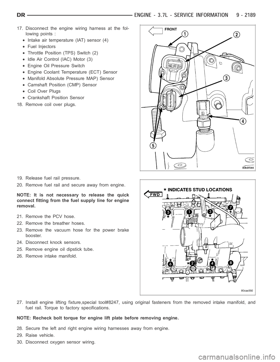
17. Disconnect the engine wiring harness at the fol-
lowing points :
Intake air temperature (IAT) sensor (4)
Fuel Injectors
Throttle Position (TPS) Switch (2)
Idle Air Control (IAC) Motor (3)
Engine Oil Pressure Switch
Engine Coolant Temperature (ECT) Sensor
Manifold Absolute Pressure MAP) Sensor
Camshaft Position (CMP) Sensor
Coil Over Plugs
Crankshaft Position Sensor
18. Remove coil over plugs.
19. Release fuel rail pressure.
20. Remove fuel rail and secure away from engine.
NOTE: It is not necessary to release the quick
connect fitting from the fuel supply line for engine
removal.
21. Remove the PCV hose.
22. Remove the breather hoses.
23. Remove the vacuum hose for the power brake
booster.
24. Disconnect knock sensors.
25. Remove engine oil dipstick tube.
26. Remove intake manifold.
27. Install engine lifting fixture,special tool#8247, using original fasteners from the removed intake manifold, and
fuel rail. Torque to factory specifications.
NOTE: Recheck bolt torque for engine lift plate before removing engine.
28. Secure the left and right engine wiring harnesses away from engine.
29. Raise vehicle.
30. Disconnect oxygen sensor wiring.
Page 1499 of 5267
31. Disconnect crankshaft postion sensor.
32. Disconnect the engine block heater power cable, if equipped.
33. Disconnect the front propshaft at the front differ-
ential and secure out of way.
NOTE: It is necessary to disconnect the front
propshaft for access to the starter and left side
exhaust flange.
34. Remove the starter (4).
Page 1502 of 5267
8. Install the starter (4).
9. Connect the crankshaft position sensor.
10. Install the engine block heater power cable, if
equipped.
CAUTION: The structural cover requires a specific
torque sequence. Failure to follow this sequence
may cause severe damage to the cover.
11. Install the structural cover.
NOTE: New clamps must be used on exhaust man-
ifold flanges. Failure to use new clamps may
result in exhaust leaks.
12. Install the left and right exhaust pipes.
13. Connect the left and right oxygen sensors.
14. Lower vehicle.
15. Remove the engine lift plate.
16. Connect the knock sensors.
17. Connect the engine to body ground straps at the
left side of the cowl.
18. Install the intake manifold.
19. Install the engine oil dipstick tube.
20. Install the power brake booster vacuum hose.
21. Install the breather hoses.
22. Install the PCV hose.
23. Install the fuel rail.
24. Install the coil over plugs.
Page 1503 of 5267
25. Connect the engine wiring harness at the follow-
ing points :
Intake air temperature (IAT) sensor (4)
Fuel Injectors
Throttle Position (TPS) Switch (2)
Idle Air Control (IAC) Motor (3)
Engine Oil Pressure Switch
Engine Coolant Temperature (ECT) Sensor
Manifold Absolute Pressure MAP) Sensor
Camshaft Position (CMP) Sensor
Coil Over Plugs
Crankshaft Position Sensor
26. Reinstall the radiator/cooling module assembly.
27. Connect lower radiator hose.
28. Connect upper radiator hose.
29. Connect throttle and speed control cables.
30. Install the heater hose assembly.
31. Install coolant recovery bottle.
32. Install the power steering pump.
33. Install the generator (3).
Page 1538 of 5267
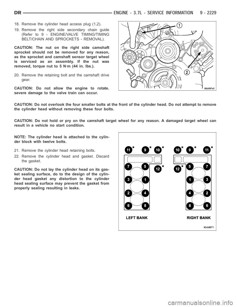
18. Remove the cylinder head access plug (1,2).
19. Remove the right side secondary chain guide
(Refer to 9 - ENGINE/VALVE TIMING/TIMING
BELT/CHAIN AND SPROCKETS - REMOVAL).
CAUTION: The nut on the right side camshaft
sprocket should not be removed for any reason,
as the sprocket and camshaft sensor target wheel
is serviced as an assembly. If the nut was
removed, torque nut to 5 Nꞏm (44 in. lbs.).
20. Remove the retaining bolt and the camshaft drive
gear.
CAUTION: Do not allow the engine to rotate.
severe damage to the valve train can occur.
CAUTION: Do not overlook the four smaller bolts at the front of the cylinderhead.Donotattempttoremove
the cylinder head without removing these four bolts.
CAUTION: Do not hold or pry on the camshaft target wheel for any reason. A damaged target wheel can
result in a vehicle no start condition.
NOTE: The cylinder head is attached to the cylin-
der block with twelve bolts.
21. Remove the cylinder head retaining bolts.
22. Remove the cylinder head and gasket. Discard
the gasket.
CAUTION: Do not lay the cylinder head on its gas-
ket sealing surface, do to the design of the cylin-
der head gasket any distortion to the cylinder
head sealing surface may prevent the gasket from
properly sealing resulting in leaks.
Page 1541 of 5267
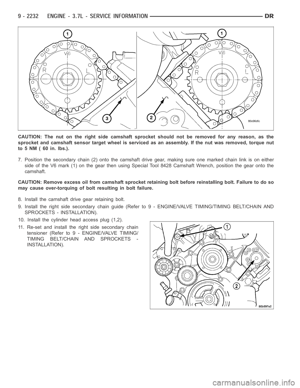
CAUTION: The nut on the right side camshaft sprocket should not be removed for any reason, as the
sprocket and camshaft sensor target wheel is serviced as an assembly. If the nut was removed, torque nut
to 5 NM ( 60 in. lbs.).
7. Position the secondary chain (2) onto the camshaft drive gear, making sure one marked chain link is on either
side of the V6 mark (1) on the gear then using Special Tool 8428 Camshaft Wrench, position the gear onto the
camshaft.
CAUTION: Remove excess oil from camshaft sprocket retaining bolt before reinstalling bolt. Failure to do so
may cause over-torquing of bolt resulting in bolt failure.
8. Install the camshaft drive gear retaining bolt.
9. Install the right side secondary chain guide (Refer to 9 - ENGINE/VALVE TIMING/TIMING BELT/CHAIN AND
SPROCKETS - INSTALLATION).
10. Install the cylinder head access plug (1,2).
11. Re-set and install the right side secondary chain
tensioner (Refer to 9 - ENGINE/VALVE TIMING/
TIMING BELT/CHAIN AND SPROCKETS -
INSTALLATION).