Page 1545 of 5267
6. Remove the camshaft position sensor.
7. Hold the camshaft with Special Tool 8428 Camshaft
Wrench (2), while removing the camshaft sprocket
bolt and sprocket.
8. Starting at the outside working inward, loosen the
camshaft bearing cap retaining bolts 1/2 turn at a
time. Repeat until all load is off the bearing caps.
CAUTION: DO NOT STAMP OR STRIKE THE CAM-
SHAFT BEARING CAPS. SEVERE DAMAGE WILL
OCCUR TO THE BEARING CAPS.
NOTE: When the camshaft is removed the rocker
arms may slide downward, mark the rocker arms
before removing camshaft.
9. Remove the camshaft bearing caps and the
camshaft.
Page 1547 of 5267
7. Using Special Tool 8428 Camshaft Wrench (2),
rotate the camshaft until the camshaft sprocket
dowel is aligned with the slot in the camshaft
sprocket. Install the sprocket onto the camshaft.
CAUTION: Remove excess oil from camshaft
sprocket bolt. Failure to do so can cause bolt
over-torque resulting in bolt failure.
8. Remove excess oil from camshaft sprocket bolt,
then install the camshaft sprocket retaining bolt and
hand tighten.
9. Remove timing chain wedge special tool 8379 (1).
10. Using Special Tool 6958 spanner wrench with
adapter pins 8346, torque the camshaft sprocket
retaining bolt to 122 Nꞏm (90 ft. lbs.).
11. Install the camshaft position sensor.
12. Install the cylinder head cover (Refer to 9 -
ENGINE/CYLINDER HEAD/CYLINDER HEAD
COVER(S) - INSTALLATION).
Page 1555 of 5267
CRANKSHAFT
DESCRIPTION
The crankshaft (1) is constructed of nodular cast iron.
The crankshaft is a three throw split pin design with
six counterweights for balancing purposes. The crank-
shaft is supported by four select fit main bearings with
the No. 2 serving as the thrust washer location. The
main journals of the crankshaft are cross drilled to
improve rod bearing lubrication. The No. 6 counter-
weight has provisions for crankshaft position sensor
target wheel (2) mounting. The select fit main bearing
markings are located on the rear side of the target
wheel. The crankshaft oil seals are one piece design.
The front oil seal is retained in the timing chain cover,
and the rear seal is pressed in to a bore formed by
the cylinder block and the bedplate assembly.
Page 1560 of 5267

BEARINGS-CRANKSHAFT MAIN
STANDARD PROCEDURE
MAIN BEARING FITTING
SELECT FIT IDENTIFICATION
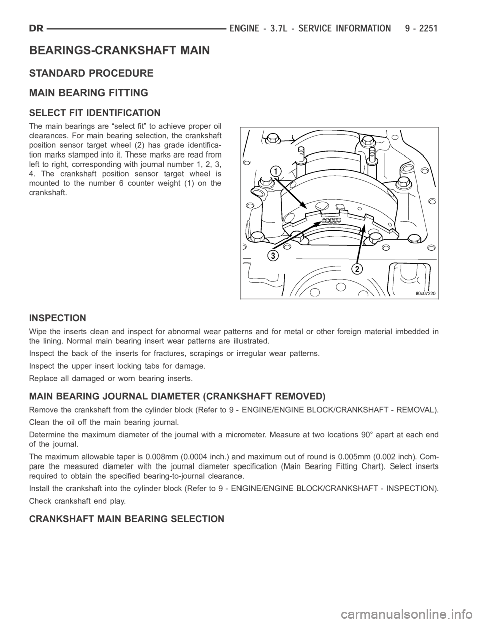
The main bearings are “select fit” to achieve proper oil
clearances. For main bearing selection, the crankshaft
position sensor target wheel (2) has grade identifica-
tion marks stamped into it. These marks are read from
left to right, corresponding with journal number 1, 2, 3,
4. The crankshaft position sensor target wheel is
mounted to the number 6 counter weight (1) on the
crankshaft.
INSPECTION
Wipe the inserts clean and inspect for abnormal wear patterns and for metalor other foreign material imbedded in
the lining. Normal main bearing insert wear patterns are illustrated.
Inspect the back of the inserts for fractures, scrapings or irregular wearpatterns.
Inspect the upper insert locking tabs for damage.
Replace all damaged or worn bearing inserts.
MAIN BEARING JOURNAL DIAMETER (CRANKSHAFT REMOVED)
Remove the crankshaft from the cylinder block (Refer to 9 - ENGINE/ENGINE BLOCK/CRANKSHAFT - REMOVAL).
Clean the oil off the main bearing journal.
Determine the maximum diameter of the journal with a micrometer. Measure at two locations 90° apart at each end
of the journal.
The maximum allowable taper is 0.008mm (0.0004 inch.) and maximum out of round is 0.005mm (0.002 inch). Com-
pare the measured diameter with the journal diameter specification (MainBearing Fitting Chart). Select inserts
required to obtain the specified bearing-to-journal clearance.
Install the crankshaft into the cylinder block (Refer to 9 - ENGINE/ENGINEBLOCK/CRANKSHAFT - INSPECTION).
Check crankshaft end play.
CRANKSHAFT MAIN BEARING SELECTION
Page 1593 of 5267

SWITCH-OIL PRESSURE
DESCRIPTION
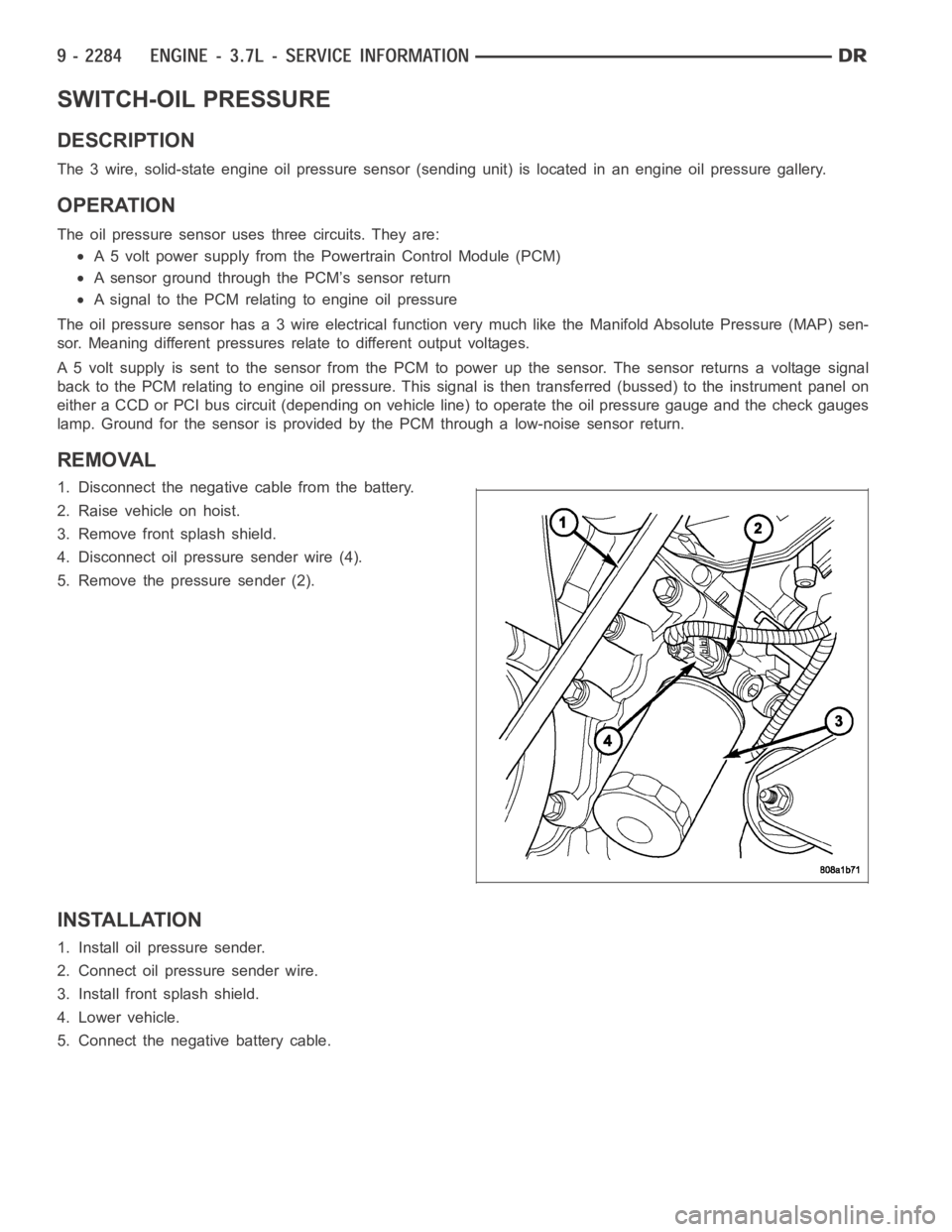
The 3 wire, solid-state engine oil pressure sensor (sending unit) is located in an engine oil pressure gallery.
OPERATION
The oil pressure sensor uses three circuits. They are:
A 5 volt power supply from the Powertrain Control Module (PCM)
A sensor ground through the PCM’s sensor return
A signal to the PCM relating to engine oil pressure
The oil pressure sensor has a 3 wire electrical function very much like the Manifold Absolute Pressure (MAP) sen-
sor. Meaning different pressures relate to different output voltages.
A 5 volt supply is sent to the sensor from the PCM to power up the sensor. The sensor returns a voltage signal
back to the PCM relating to engine oil pressure. This signal is then transferred (bussed) to the instrument panel on
either a CCD or PCI bus circuit (depending on vehicle line) to operate the oil pressure gauge and the check gauges
lamp. Ground for the sensor is provided by the PCM through a low-noise sensor return.
REMOVAL
1. Disconnect the negative cable from the battery.
2. Raise vehicle on hoist.
3. Remove front splash shield.
4. Disconnect oil pressure sender wire (4).
5. Remove the pressure sender (2).
INSTALLATION
1. Install oil pressure sender.
2. Connect oil pressure sender wire.
3. Install front splash shield.
4. Lower vehicle.
5. Connect the negative battery cable.
Page 1600 of 5267

MANIFOLD-INTAKE
DESCRIPTION
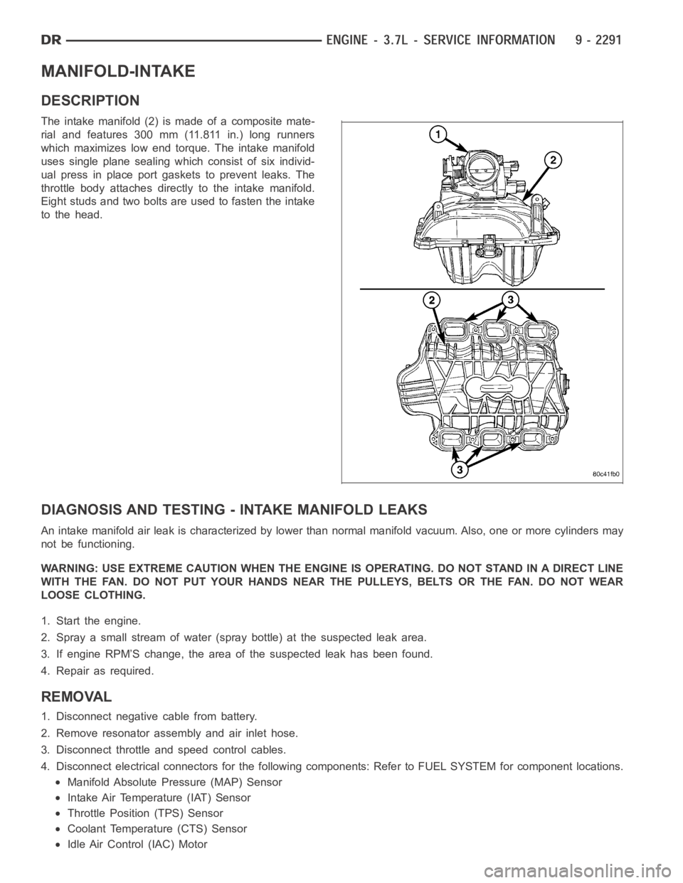
The intake manifold (2) is made of a composite mate-
rial and features 300 mm (11.811 in.) long runners
which maximizes low end torque. The intake manifold
uses single plane sealing which consist of six individ-
ual press in place port gaskets to prevent leaks. The
throttle body attaches directly to the intake manifold.
Eight studs and two bolts are used to fasten the intake
to the head.
DIAGNOSIS AND TESTING -INTAKE MANIFOLD LEAKS
An intake manifold air leak is characterized by lower than normal manifoldvacuum. Also, one or more cylinders may
not be functioning.
WARNING: USE EXTREME CAUTION WHEN THE ENGINE IS OPERATING. DO NOT STAND IN ADIRECT LINE
WITH THE FAN. DO NOT PUT YOUR HANDS NEAR THE PULLEYS, BELTS OR THE FAN. DO NOT WEAR
LOOSE CLOTHING.
1. Start the engine.
2. Spray a small stream of water (spray bottle) at the suspected leak area.
3. If engine RPM’S change, the area of the suspected leak has been found.
4. Repair as required.
REMOVAL
1. Disconnect negative cable from battery.
2. Remove resonator assembly and air inlet hose.
3. Disconnect throttle and speed control cables.
4. Disconnect electrical connectors for the following components: Referto FUEL SYSTEM for component locations.
Manifold Absolute Pressure (MAP) Sensor
Intake Air Temperature (IAT) Sensor
Throttle Position (TPS) Sensor
Coolant Temperature (CTS) Sensor
Idle Air Control (IAC) Motor
Page 1601 of 5267

5. Disconnect vapor purge hose, brake booster hose, speed control servo hose, positive crankcase ventilation
(PCV) hose.
6. Disconnect generator electrical connections.
7. Disconnect air conditioning compressor electrical connections.
8. Disconnect left and right radio suppressor straps.
9. Disconnect and remove ignition coil towers.
10. Remove top oil dipstick tube retaining bolt and ground strap.
11. Bleed fuel system (Refer to 14 - FUEL SYSTEM/FUEL DELIVERY - STANDARD PROCEDURE).
12. Remove fuel rail.
13. Remove throttle body assembly and mounting bracket.
14. Drain cooling system below coolant temperature level (Refer to 7 - COOLING - STANDARD PROCEDURE).
15. Remove the heater hoses from the engine front cover and the heater core.
16. Unclip and remove heater hoses and tubes from intake manifold.
17. Remove coolant temperature sensor (Refer to 7 - COOLING/ENGINE/ENGINE COOLANT TEMP SENSOR -
REMOVAL).
18. Remove intake manifold retaining fasteners in reverse order of tightening sequence.
19. Remove intake manifold.
INSTALLATION
1. Install intake manifold gaskets.
2. Install intake manifold.
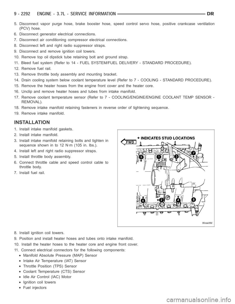
3. Install intake manifold retaining bolts and tighten in
sequence shown in to 12 Nꞏm (105 in. lbs.).
4. Install left and right radio suppressor straps.
5. Install throttle body assembly.
6. Connect throttle cable and speed control cable to
throttle body.
7. Install fuel rail.
8. Install ignition coil towers.
9. Position and install heater hoses and tubes onto intake manifold.
10. Install the heater hoses to the heater core and engine front cover.
11. Connect electrical connectors for the following components:
Manifold Absolute Pressure (MAP) Sensor
Intake Air Temperature (IAT) Sensor
Throttle Position (TPS) Sensor
Coolant Temperature (CTS) Sensor
Idle Air Control (IAC) Motor
Ignition coil towers
Fuel injectors
Page 1617 of 5267
6. Remove power steering pump (Refer to 19 -
STEERING/PUMP - REMOVAL).
7. Remove access plug from left and right cylinder
heads for access to chain guide fasteners.
8. Remove the oil fill housing to gain access to the
right side tensioner arm fastener.
9. Remove crankshaft damper (Refer to 9 - ENGINE/
ENGINE BLOCK/VIBRATION DAMPER -
REMOVAL) and timing chain cover (Refer to 9 -
ENGINE/VALVE TIMING/TIMING BELT / CHAIN
COVER(S) - REMOVAL).
10. Collapse and pin primary chain tensioner.
CAUTION: Plate behind left secondary chain ten-
sioner could fall into oil pan. Therefore, cover pan
opening.
11. Remove secondary chain tensioners.
12. Remove camshaft position sensor (2).