Page 2045 of 5267
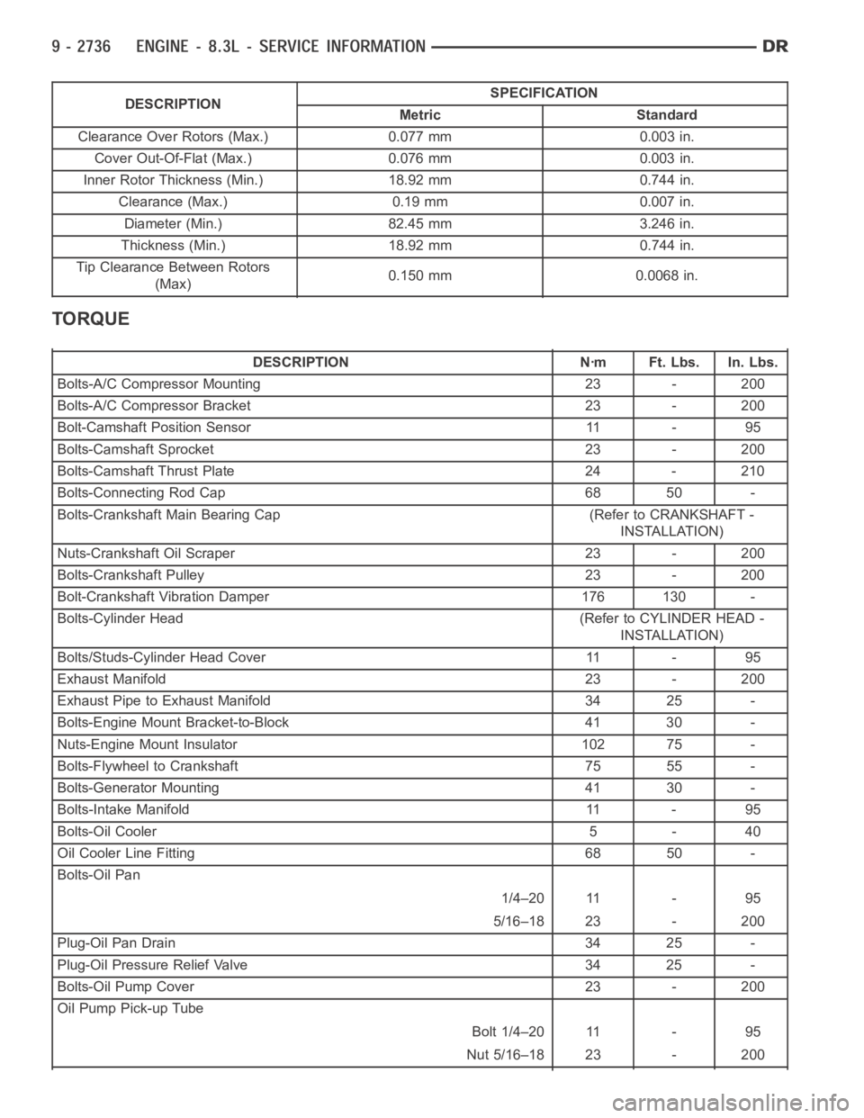
DESCRIPTIONSPECIFICATION
Metric Standard
Clearance Over Rotors (Max.) 0.077 mm 0.003 in.
Cover Out-Of-Flat (Max.) 0.076 mm 0.003 in.
Inner Rotor Thickness (Min.) 18.92 mm 0.744 in.
Clearance (Max.) 0.19 mm 0.007 in.
Diameter (Min.) 82.45 mm 3.246 in.
Thickness (Min.) 18.92 mm 0.744 in.
Tip Clearance Between Rotors
(Max)0.150 mm 0.0068 in.
TORQUE
DESCRIPTION Nꞏm Ft. Lbs. In. Lbs.
Bolts-A/C Compressor Mounting 23 - 200
Bolts-A/C Compressor Bracket 23 - 200
Bolt-Camshaft Position Sensor 11 - 95
Bolts-Camshaft Sprocket 23 - 200
Bolts-Camshaft Thrust Plate 24 - 210
Bolts-Connecting Rod Cap 68 50 -
Bolts-Crankshaft Main Bearing Cap (Refer to CRANKSHAFT -
INSTALLATION)
Nuts-Crankshaft Oil Scraper 23 - 200
Bolts-Crankshaft Pulley 23 - 200
Bolt-Crankshaft Vibration Damper 176 130 -
Bolts-Cylinder Head (Refer to CYLINDER HEAD -
INSTALLATION)
Bolts/Studs-Cylinder Head Cover 11 - 95
Exhaust Manifold 23 - 200
Exhaust Pipe to Exhaust Manifold 34 25 -
Bolts-Engine Mount Bracket-to-Block 41 30 -
Nuts-Engine Mount Insulator 102 75 -
Bolts-Flywheel to Crankshaft 75 55 -
Bolts-Generator Mounting 41 30 -
Bolts-Intake Manifold 11 - 95
Bolts-Oil Cooler 5 - 40
Oil Cooler Line Fitting 68 50 -
Bolts-Oil Pan
1/4–20 11 - 95
5/16–18 23 - 200
Plug-Oil Pan Drain 34 25 -
Plug-Oil Pressure Relief Valve 34 25 -
Bolts-Oil Pump Cover 23 - 200
Oil Pump Pick-up Tube
Bolt 1/4–20 11 - 95
Nut 5/16–18 23 - 200
Page 2046 of 5267
DESCRIPTION Nꞏm Ft. Lbs. In. Lbs.
Oil Filter18 - 160
Oil Pressure Sensor 8.5 - 75
Oil Temperature Sensor 8.5 - 75
Bolts-Power Steering Pump Mounting 23 - 200
Bolts-Rear Crankshaft Seal Retainer 11 - 95
Bolts-Rocker Arm 35 26 -
Spark Plugs27 20 -
Bolts-Starter Mounting 41 30 -
Bolts-Throttle Body 11 - 95
Bolts-Timing Chain Cover 23 - 200
Bolts-Water Pump Mounting 11 - 95
Page 2057 of 5267
MANIFOLD-INTAKE
DIAGNOSIS AND TESTING
INTAKE MANIFOLD LEAKS
An intake manifold air leak is characterized by lower than normal manifoldvacuum, rough idle, or engine misfire.
WARNING: USE EXTREME CAUTION WHEN THE ENGINE IS OPERATING. DO NOT STAND IN ADIRECT LINE
WITH THE FAN. DO NOT PUT YOUR HANDS NEAR THE PULLEYS, BELT OR THE FAN. DO NOT WEAR
LOOSE CLOTHING.
1. Start the engine.
2. Spray a small stream of water (Spray Bottle) at the suspected leak area.
3. If engine RPM’S change, the area of the suspected leak has been found.
4. Repair as required.
REMOVAL
NOTE: Care must be taken to protect the intake
manifold powder coating from scrapes and abra-
sions.
1. Perform the fuel system pressure release proce-
dure,before attempting any repairs.(Refer to 14
- FUEL SYSTEM/FUEL DELIVERY - STANDARD
PROCEDURE - FUEL SYSTEM PRESSURE
RELEASE PROCEDURE).
2. Disconnect negative battery cable.
3. Disconnect throttle body air inlet duct, IAT sensor,
CCV hose and remove air cleaner cover (Refer to
9 - ENGINE/AIR INTAKE SYSTEM - REMOVAL).
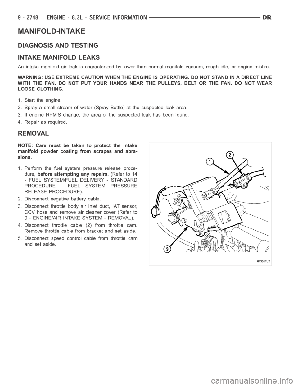
4. Disconnect throttle cable (2) from throttle cam.
Remove throttle cable from bracket and set aside.
5. Disconnect speed control cable from throttle cam
and set aside.
Page 2058 of 5267
6. Disconnect brake booster vacuum hose from the
intake manifold and set aside.
WARNING: WRAP A SHOP TOWEL AROUND FUEL
LINE TO CATCH ANY GASOLINE SPILLAGE.
7. Disconnect fuel line quick connect fitting from fuel
rail (Refer to 14 - FUEL SYSTEM/FUEL DELIV-
ERY/QUICK CONNECT FITTING - STANDARD
PROCEDURE).
8. Disconnect the following electrical connectors:
Left cylinder head fuel injectors
MAP sensor
Engine Coolant Temperature (ECT) Sensor
Idle Speed Control Sensor (ISC)
Throttle Position Sensor (TPS) (1)
Right cylinder head fuel injectors
9. Carefully separate the fuel injector harness push
pins from the intake manifold.
Page 2062 of 5267
10. Reconnect the following electrical connectors:
Left cylinder head fuel injectors
Engine Coolant Temperature (ECT) Sensor
MAP sensor
Idle Speed Control
Throttle Position Sensor
Right cylinder head fuel injectors
11. Install air cleaner cover assembly, connect throttle
body air inlet hose, CCV hose and connect the
Intake Air Temperature Sensor (Refer to 9 -
ENGINE/AIR INTAKE SYSTEM - INSTALLATION).
12. Connect negative battery cable.
13. With the Scan Tool, use the ASD Fuel System
Test to pressurize fuel system to check for leaks.
CAUTION: When using the ASD Fuel System Test,
the Auto Shutdown (ASD) relay will remain ener-
gized for 7 minutes or until the ignition switch is
turned to the OFF position, or Stop All Test is selected.
Page 2068 of 5267
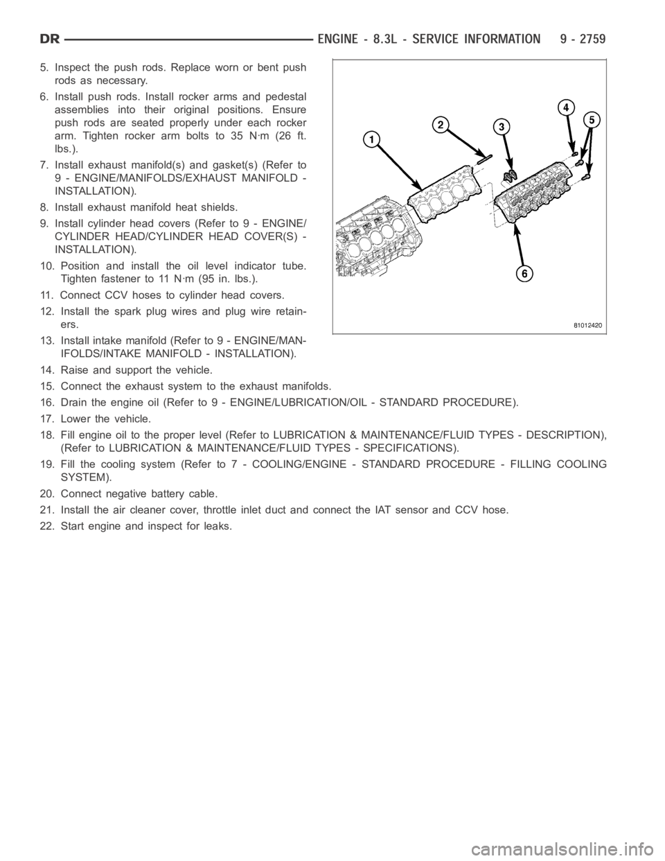
5. Inspect the push rods. Replace worn or bent push
rods as necessary.
6. Install push rods. Install rocker arms and pedestal
assemblies into their original positions. Ensure
push rods are seated properly under each rocker
arm.Tightenrockerarmboltsto35Nꞏm(26ft.
lbs.).
7. Install exhaust manifold(s) and gasket(s) (Refer to
9 - ENGINE/MANIFOLDS/EXHAUST MANIFOLD -
INSTALLATION).
8. Install exhaust manifold heat shields.
9. Install cylinder head covers (Refer to 9 - ENGINE/
CYLINDER HEAD/CYLINDER HEAD COVER(S) -
INSTALLATION).
10. Position and install the oil level indicator tube.
Tighten fastener to 11 Nꞏm (95 in. lbs.).
11. Connect CCV hoses to cylinder head covers.
12. Install the spark plug wires and plug wire retain-
ers.
13. Install intake manifold (Refer to 9 - ENGINE/MAN-
IFOLDS/INTAKE MANIFOLD - INSTALLATION).
14. Raise and support the vehicle.
15. Connect the exhaust systemto the exhaust manifolds.
16. Drain the engine oil (Refer to 9 - ENGINE/LUBRICATION/OIL - STANDARD PROCEDURE).
17. Lower the vehicle.
18. Fill engine oil to the proper level (Refer to LUBRICATION & MAINTENANCE/FLUID TYPES - DESCRIPTION),
(Refer to LUBRICATION & MAINTENANCE/FLUID TYPES - SPECIFICATIONS).
19. Fill the cooling system (Refer to 7 - COOLING/ENGINE - STANDARD PROCEDURE - FILLING COOLING
SYSTEM).
20. Connect negative battery cable.
21. Install the air cleaner cover, throttle inlet duct and connect the IAT sensor and CCV hose.
22. Start engine and inspect for leaks.
Page 2078 of 5267
COVER-TIMING CHAIN
REMOVAL
1. Disconnect negative battery cable.
2. Disconnect throttle body air inlet duct at the throttle
body, CCV hose, disconnect the IAT sensor and
remove air cleaner housing cover (Refer to 9 -
ENGINE/AIR INTAKE SYSTEM - REMOVAL).
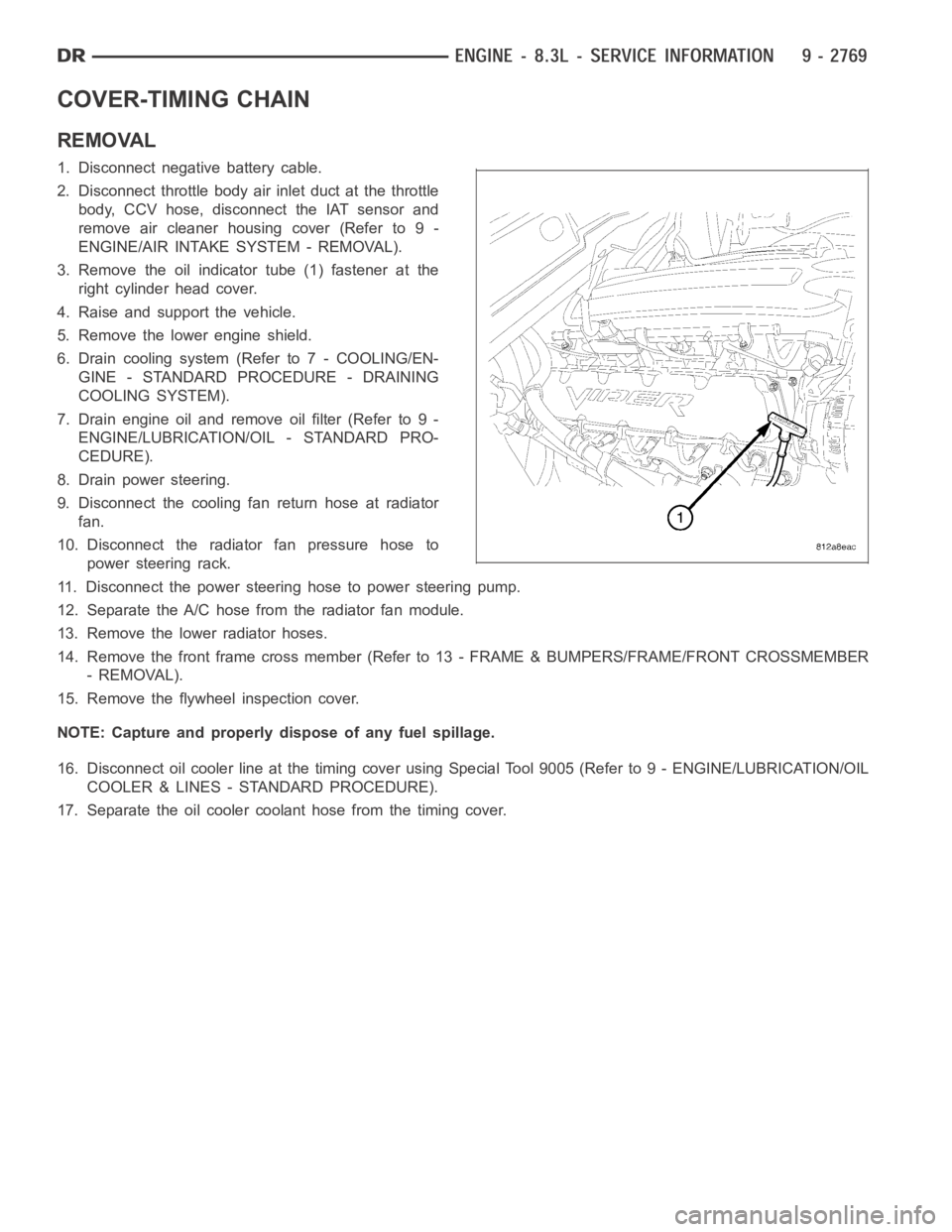
3. Remove the oil indicator tube (1) fastener at the
right cylinder head cover.
4. Raise and support the vehicle.
5. Remove the lower engine shield.
6. Drain cooling system (Refer to 7 - COOLING/EN-
GINE - STANDARD PROCEDURE - DRAINING
COOLING SYSTEM).
7. Drain engine oil and remove oil filter (Refer to 9 -
ENGINE/LUBRICATION/OIL - STANDARD PRO-
CEDURE).
8. Drain power steering.
9. Disconnect the cooling fan return hose at radiator
fan.
10. Disconnect the radiator fan pressure hose to
power steering rack.
11. Disconnect the power steering hose to power steering pump.
12. Separate the A/C hose from the radiator fan module.
13. Remove the lower radiator hoses.
14. Remove the front frame cross member (Refer to 13 - FRAME & BUMPERS/FRAME/FRONT CROSSMEMBER
- REMOVAL).
15. Remove the flywheel inspection cover.
NOTE: Capture and properly dispose of any fuel spillage.
16. Disconnect oil cooler line at the timing cover using Special Tool 9005 (Refer to 9 - ENGINE/LUBRICATION/OIL
COOLER & LINES - STANDARD PROCEDURE).
17. Separate the oil cooler coolant hose from the timing cover.
Page 2080 of 5267
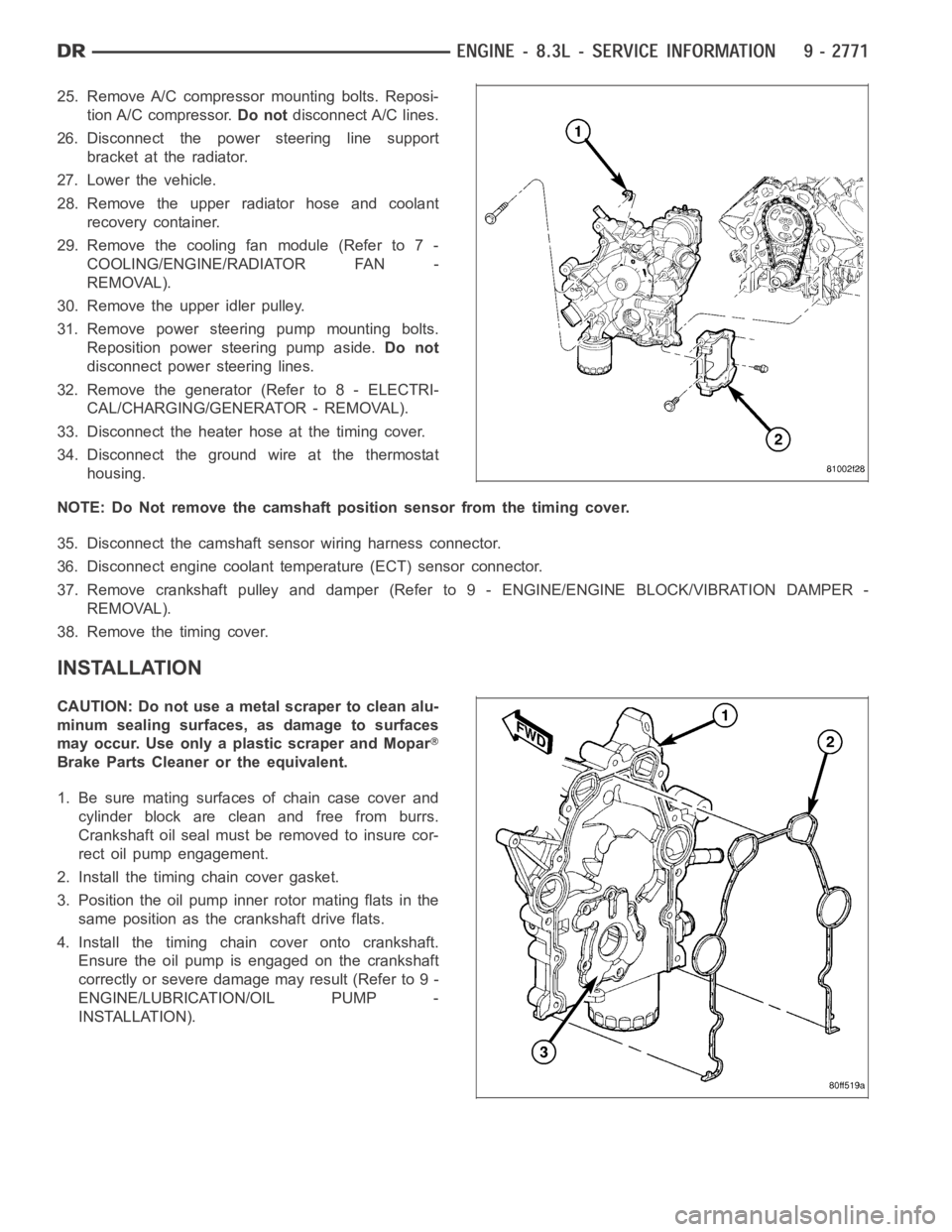
25. Remove A/C compressor mounting bolts. Reposi-
tion A/C compressor.Do notdisconnect A/C lines.
26. Disconnect the power steering line support
bracket at the radiator.
27. Lower the vehicle.
28. Remove the upper radiator hose and coolant
recovery container.
29. Remove the cooling fan module (Refer to 7 -
COOLING/ENGINE/RADIATOR FAN -
REMOVAL).
30. Remove the upper idler pulley.
31. Remove power steering pump mounting bolts.
Reposition power steering pump aside.Do not
disconnect power steering lines.
32. Remove the generator (Refer to 8 - ELECTRI-
CAL/CHARGING/GENERATOR - REMOVAL).
33. Disconnect the heater hose at the timing cover.
34. Disconnect the ground wire at the thermostat
housing.
NOTE: Do Not remove the camshaft position sensor from the timing cover.
35. Disconnect the camshaft sensor wiring harness connector.
36. Disconnect engine coolant temperature (ECT) sensor connector.
37. Remove crankshaft pulley and damper (Refer to 9 - ENGINE/ENGINE BLOCK/VIBRATION DAMPER -
REMOVAL).
38. Remove the timing cover.
INSTALLATION
CAUTION: Do not use a metal scraper to clean alu-
minum sealing surfaces, as damage to surfaces
may occur. Use only a plastic scraper and Mopar
Brake Parts Cleaner or the equivalent.
1. Be sure mating surfaces of chain case cover and
cylinder block are clean and free from burrs.
Crankshaft oil seal must be removed to insure cor-
rect oil pump engagement.
2. Install the timing chain cover gasket.
3. Position the oil pump inner rotor mating flats in the
same position as the crankshaft drive flats.
4. Install the timing chain cover onto crankshaft.
Ensure the oil pump is engaged on the crankshaft
correctly or severe damage may result (Refer to 9 -
ENGINE/LUBRICATION/OIL PUMP -
INSTALLATION).