2006 DODGE RAM SRT-10 sensor
[x] Cancel search: sensorPage 2143 of 5267
CONVERTER-CATALYTIC
DESCRIPTION
WARNING: THE NORMAL OPERATING TEMPERATURE OF THE EXHAUST SYSTEM IS VERY HIGH. THERE-
FORE, NEVER WORK AROUND OR ATTEMPT TO SERVICE ANY PART OF THE EXHAUST SYSTEMUNTIL IT
IS COOLED. SPECIAL CARE SHOULD BE TAKEN WHEN WORKING NEAR THE CATALYTIC CONVERTER.
THE TEMPERATURE OF THE CONVERTER RISES TO A HIGH LEVEL AFTER A SHORT PERIOD OFENGINE
OPERATION TIME.
CAUTION: DO NOT remove spark plug wires from plugs or by any other means short out cylinders. Failure
of the catalytic converter can occur due to a temperature increase caused by unburned fuel passing
through the converter.
The stainless steel catalytic converter body is designed to last the life of the vehicle. Excessive heat can result in
bulging or other distortion, but excessive heat will not be the fault of theconverter. If unburned fuel enters the con-
verter, overheating may occur. If a converter is heat-damaged, correct the cause of the damage at the same time
the converter is replaced. Also, inspect all other components of the exhaust system for heat damage.
Unleaded gasoline must be used to avoid contaminating the catalyst core.
50 State emission vehicles incorporate two mini catalytic converters located after the exhaust manifolds and before
the inline catalytic converter.
OPERATION
The catalytic converter captures and burns any unburned fuel mixture exiting the combustion chambers during the
exhaust stroke of the engine. This process aids in reducing emissions output.
REMOVAL
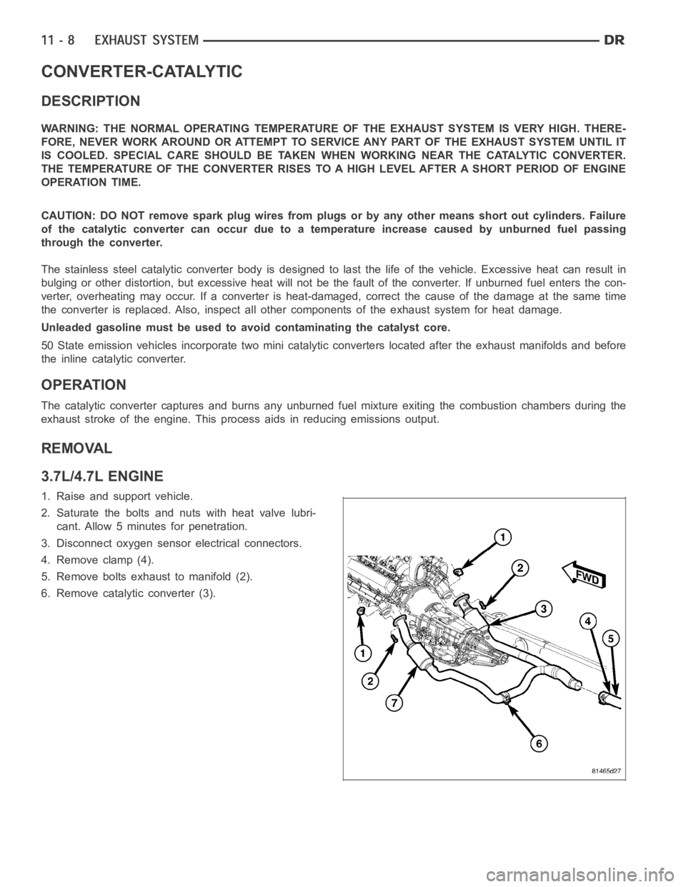
3.7L/4.7L ENGINE
1. Raise and support vehicle.
2. Saturate the bolts and nuts with heat valve lubri-
cant. Allow 5 minutes for penetration.
3. Disconnect oxygen sensor electrical connectors.
4. Remove clamp (4).
5. Remove bolts exhaust to manifold (2).
6. Remove catalytic converter (3).
Page 2144 of 5267
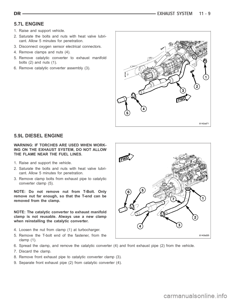
5.7L ENGINE
1. Raise and support vehicle.
2. Saturate the bolts and nuts with heat valve lubri-
cant. Allow 5 minutes for penetration.
3. Disconnect oxygen sensor electrical connectors.
4. Remove clamps and nuts (4).
5. Remove catalytic converter to exhaust manifold
bolts (2) and nuts (1).
6. Remove catalytic converter assembly (3).
5.9L DIESEL ENGINE
WARNING: IF TORCHES ARE USED WHEN WORK-
ING ON THE EXHAUST SYSTEM, DO NOT ALLOW
THE FLAME NEAR THE FUEL LINES.
1. Raise and support the vehicle.
2. Saturate the bolts and nuts with heat valve lubri-
cant. Allow 5 minutes for penetration.
3. Remove clamp bolts from exhaust pipe to catalytic
converter clamp (5).
NOTE: Do not remove nut from T-Bolt. Only
remove nut far enough, so that the T-end can be
removed from the clamp.
NOTE: The catalytic converter to exhaust manifold
clamp is not reusable. Always use a new clamp
when reinstalling the catalytic converter.
4. Loosen the nut from clamp (1) at turbocharger.
5. Remove the T-bolt end of the fastener, from the
clamp (1).
6. Spread the clamp, and remove the catalytic converter (4) and front exhaust pipe (2) from the vehicle.
7. Discard the clamp.
8. Remove front exhaust pipe to catalytic converter clamp (3).
9. Separate front exhaust pipe (2) from catalytic converter (4).
Page 2145 of 5267
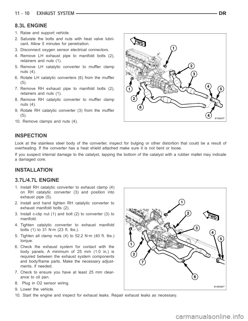
8.3L ENGINE
1. Raise and support vehicle.
2. Saturate the bolts and nuts with heat valve lubri-
cant. Allow 5 minutes for penetration.
3. Disconnect oxygen sensor electrical connectors.
4. Remove LH exhaust pipe to manifold bolts (2),
retainers and nuts (1).
5. Remove LH catalytic converter to muffler clamp
nuts (4).
6. Rotate LH catalytic converters (6) from the muffler
(5).
7. Remove RH exhaust pipe to manifold bolts (2),
retainers and nuts (1).
8. Remove RH catalytic converter to muffler clamp
nuts (4).
9. Rotate RH catalytic converter (3) from the muffler
(5).
10. Remove clamps and nuts (4).
INSPECTION
Look at the stainless steel body of the converter, inspect for bulging or other distortion that could be a result of
overheating. If the converter has a heat shield attached make sure it is notbent or loose.
If you suspect internal damage to the catalyst, tapping the bottom of the catalyst with a rubber mallet may indicate
a damaged core.
INSTALLATION
3.7L/4.7L ENGINE
1. Install RH catalytic converter to exhaust clamp (4)
on RH catalytic converter (3) and position into
exhaust pipe (5).
2. Install and hand tighten RH catalytic converter to
exhaust manifold bolts (2).
3. Install c-clip nut (1) and bolt (2) to converter (3) to
manifold.
4. Tighten catalytic converter to exhaust manifold
bolts(1)to31Nꞏm(23ft.lbs.).
5. Tighten all clamp nuts (4) to 52.2 Nꞏm (40 ft. lbs.)
torque.
6. Check the exhaust system for contact with the
body panels. A minimum of 25 mm (1.0 in.) is
required between the exhaust system components
and body/frame parts. Make the necessary adjust-
ments, if needed.
7. Check to ensure you have at least 25 mm clear-
ance to oil pan.
8. Plug in O2 sensor wiring.
9. Lower the vehicle.
10. Start the engine and inspect for exhaust leaks. Repair exhaust leaks asnecessary.
Page 2238 of 5267
FUEL SYSTEM
TABLE OF CONTENTS
page page
FUEL DELIVERY - GAS....................1
FUEL INJECTION - GAS...................44FUEL DELIVERY - DIESEL................104
FUEL INJECTION - DIESEL...............140
page page
FUEL DELIVERY - GAS
DESCRIPTION ................................. 2
OPERATION ................................... 4
STANDARD PROCEDURE
STANDARD PROCEDURE - FUEL SYSTEM
PRESSURE RELEASE........................ 4
STANDARD PROCEDURE - DRAINING FUEL
TANK - EXCEPT DIESEL...................... 5
SPECIFICATIONS
FUEL SYSTEM PRESSURE ................... 5
TORQUE - EXCEPT DIESEL.................. 5
SPECIAL TOOLS
FUEL SYSTEM.............................. 8
FUEL FILTER/PRESSURE REGULATOR
DESCRIPTION ................................. 9
OPERATION ................................... 9
SENSOR - FUEL LEVEL SENDING UNIT
DESCRIPTION ................................ 10
OPERATION .................................. 10
REMOVAL .................................... 10
INSTALLATION ................................ 11
LINES, FUEL
DESCRIPTION ................................ 12
FITTING-QUICK CONNECT
DESCRIPTION ................................ 13
STANDARD PROCEDURE - QUICK-CONNECT
FITTINGS .................................. 13
MODULE-FUEL PUMP
DESCRIPTION ................................ 19OPERATION .................................. 19
MODULE - FUEL PUMP
DESCRIPTION ................................ 20
OPERATION .................................. 20
REMOVAL .................................... 20
INSTALLATION ............................... 21
RAIL - FUEL
DESCRIPTION ................................ 22
OPERATION .................................. 22
REMOVAL
3.7L V-6 .................................... 22
4.7L V-8 .................................... 23
5.7L ....................................... 24
8.3L - SRT-10 ............................... 26
INSTALLATION
3.7L ....................................... 30
4.7L ....................................... 31
5.7L ....................................... 32
8.3L - SRT-10 ............................... 32
TA N K - F U E L
DESCRIPTION ................................ 34
OPERATION .................................. 34
REMOVAL- EXCEPT DIESEL ................... 34
INSTALLATION - EXCEPT DIESEL . ............. 38
FILTER - INLET
REMOVAL .................................... 43
INSTALLATION ............................... 43
Page 2239 of 5267
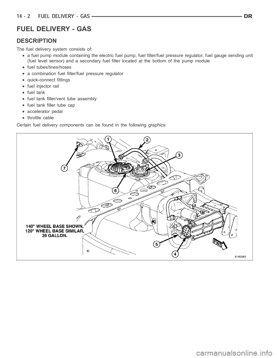
FUEL DELIVERY - GAS
DESCRIPTION
The fuel delivery system consists of:
a fuel pump module containing the electric fuel pump, fuel filter/fuel pressure regulator, fuel gauge sending unit
(fuel level sensor) and a secondary fuel filter located at the bottom of thepump module
fuel tubes/lines/hoses
a combination fuel filter/fuel pressure regulator
quick-connect fittings
fuel injector rail
fuel tank
fuel tank filler/vent tube assembly
fuel tank filler tube cap
accelerator pedal
throttle cable
Certain fuel delivery components can be found in the following graphics:
Page 2242 of 5267

8. Connect other end of jumper wire to positive side of battery.
9. Connect one end of a second jumper wire to remaining injector terminal.
CAUTION: Powering an injector for more than a few seconds will permanentlydamage the injector.
10. Momentarily touch other end of jumper wire to negative terminal of battery for no more than a few seconds.
11. Place a rag or towel below fuel line quick-connect fitting at fuel rail.
12. Disconnect quick-connect fitting at fuel rail. Refer to Quick-Connect Fittings.
13. Return fuel pump relay to PDC.
14. One or more Diagnostic Trouble Codes (DTC’s) may have been stored in PCMmemory due to fuel pump relay
removal. The DRB
scantoolmustbeusedtoeraseaDTC.
STANDARD PROCEDURE - DRAINING FUEL TANK - EXCEPT DIESEL
WARNING: The fuel system may be under constant fuel pressure even with the engine off. This pressure
must be released before servicing fuel tank.
Two different procedures may be used to drain fuel tank: through the fuel fill fitting on tank, or using a diagnostic
scan tool to activate the fuel pump relay. Due to a one-way check valve installed into the fuel fill opening fitting at
the tank, the tank cannot be drained conventionally at the fill cap.
The quickest draining procedure involves removing the rubber fuel fill hose at the fuel tank.
As an alternative procedure, the electric fuel pump may be activated allowingtanktobedrainedatfuelrailcon-
nection. Refer to diagnostic scan tool for fuel pump activation procedures. Before disconnecting fuel line at fuel rail,
release fuel pressure. Refer to the Fuel System Pressure Release Procedure for procedures. Attach end of special
test hose tool number 6631 or 6539 at fuel rail disconnection (tool number 6631isusedon5/16”fuellineswhile
tool number 6539 is used on 3/8” fuel lines). Position opposite end of this hose tool to an approved gasoline drain-
ing station. Activate fuel pump and drain tank until empty.
If electric fuel pump is not operating, fuel must be drained through fuel fill fitting at tank. Refer to following proce-
dures.
1. Release fuel system pressure.
2. Raise vehicle.
3. Thoroughly clean area around fuel fill fitting and rubber fuel fill hoseat tank.
4. If vehicle is equipped with 4 doors and a 6 foot (short) box, remove left-rear tire/wheel.
5. Loosen clamp and disconnect rubber fuel fill hose at tank fitting. Usingan approved gas holding tank, drain fuel
tank through this fitting.
SPECIFICATIONS
FUEL SYSTEM PRESSURE
58 psi +/- 2 psi
TORQUE - EXCEPT DIESEL
DESCRIPTION N-m Ft. Lbs. In. Lbs.
Accelerator Pedal Bracket
Mounting12 - 105
Accelerator Pedal Position
Sensor Bracket-to-Battery
Tray Bolts3-30
Crankshaft Position
Sensor - 3.7L28 21 -
Crankshaft Position
Sensor - 4.7L28 21 -
Page 2243 of 5267
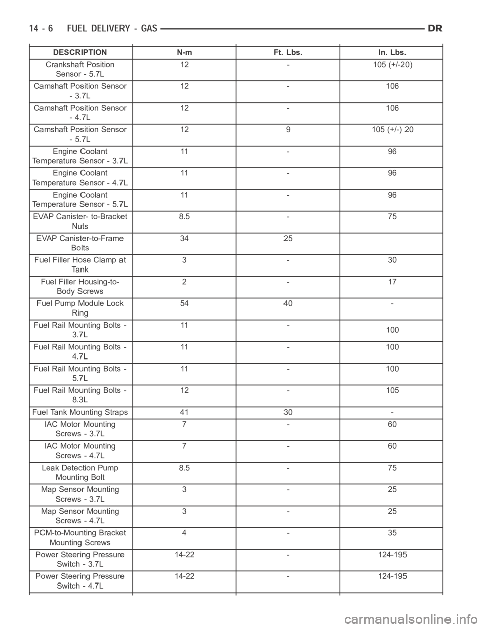
DESCRIPTION N-m Ft. Lbs. In. Lbs.
Crankshaft Position
Sensor - 5.7L12 - 105 (+/-20)
Camshaft Position Sensor
-3.7L12 - 106
Camshaft Position Sensor
-4.7L12 - 106
Camshaft Position Sensor
-5.7L12 9 105 (+/-) 20
Engine Coolant
Temperature Sensor - 3.7L11 - 9 6
Engine Coolant
Temperature Sensor - 4.7L11 - 9 6
Engine Coolant
Temperature Sensor - 5.7L11 - 9 6
EVAP Canister- to-Bracket
Nuts8.5 - 75
EVAP Canister-to-Frame
Bolts34 25
Fuel Filler Hose Clamp at
Tank3-30
Fuel Filler Housing-to-
Body Screws2-17
Fuel Pump Module Lock
Ring54 40 -
Fuel Rail Mounting Bolts -
3.7L11 -
100
Fuel Rail Mounting Bolts -
4.7L11 - 1 0 0
Fuel Rail Mounting Bolts -
5.7L11 - 1 0 0
Fuel Rail Mounting Bolts -
8.3L12 - 105
Fuel Tank Mounting Straps 41 30 -
IAC Motor Mounting
Screws - 3.7L7-60
IAC Motor Mounting
Screws - 4.7L7-60
Leak Detection Pump
Mounting Bolt8.5 - 75
Map Sensor Mounting
Screws - 3.7L3-25
Map Sensor Mounting
Screws - 4.7L3-25
PCM-to-Mounting Bracket
Mounting Screws4-35
Power Steering Pressure
Switch - 3.7L14-22 - 124-195
Power Steering Pressure
Switch - 4.7L14-22 - 124-195
Page 2244 of 5267
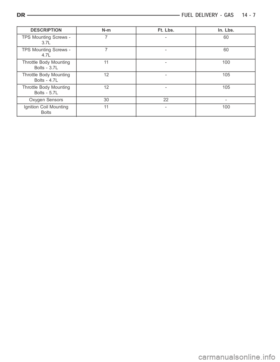
DESCRIPTION N-m Ft. Lbs. In. Lbs.
TPS Mounting Screws -
3.7L7-60
TPS Mounting Screws -
4.7L7-60
Throttle Body Mounting
Bolts - 3.7L11 - 1 0 0
Throttle Body Mounting
Bolts - 4.7L12 - 105
Throttle Body Mounting
Bolts - 5.7L12 - 105
Oxygen Sensors 30 22 -
Ignition Coil Mounting
Bolts11 - 1 0 0