Page 2290 of 5267
5.7L V-8
The Crankshaft Position (CKP) sensor (4) is located at
the right-rear side of the engine cylinder block. It is
positioned and bolted into a machined hole in the
engine block.
1. Raise vehicle.
2. Disconnect CKP electrical connector at sensor.
3. Remove CKP mounting bolt (3).
4. Carefully twist sensor (4) from cylinder block.
5. Remove sensor from vehicle.
6. Check condition of sensor O-ring.
8.3L - SRT-10
The sensor is located at the rear lower passenger side
of motor.
Page 2291 of 5267
1. Disconnect electrical connector from crankshaft
position sensor.
2. Remove sensor mounting bolt.
3. Pull sensor out. A light tap to top of sensor may
ease removal.
INSTALLATION
3.7L V-6
1. Clean out machined hole in engine block.
2. Apply a small amount of engine oil to sensor O-ring
(3).
3. Install sensor into engine block with a slight rocking
and twisting action.
CAUTION: Before tightening sensor mounting bolt,
be sure sensor is completely flush to cylinder
block. If sensor is not flush, damage to sensor
mounting tang may result.
4. Install mounting bolt and tighten to 28 Nꞏm (21 ft.
lbs.) torque.
5. Connect electrical connector to sensor.
6. Lower vehicle.
Page 2292 of 5267

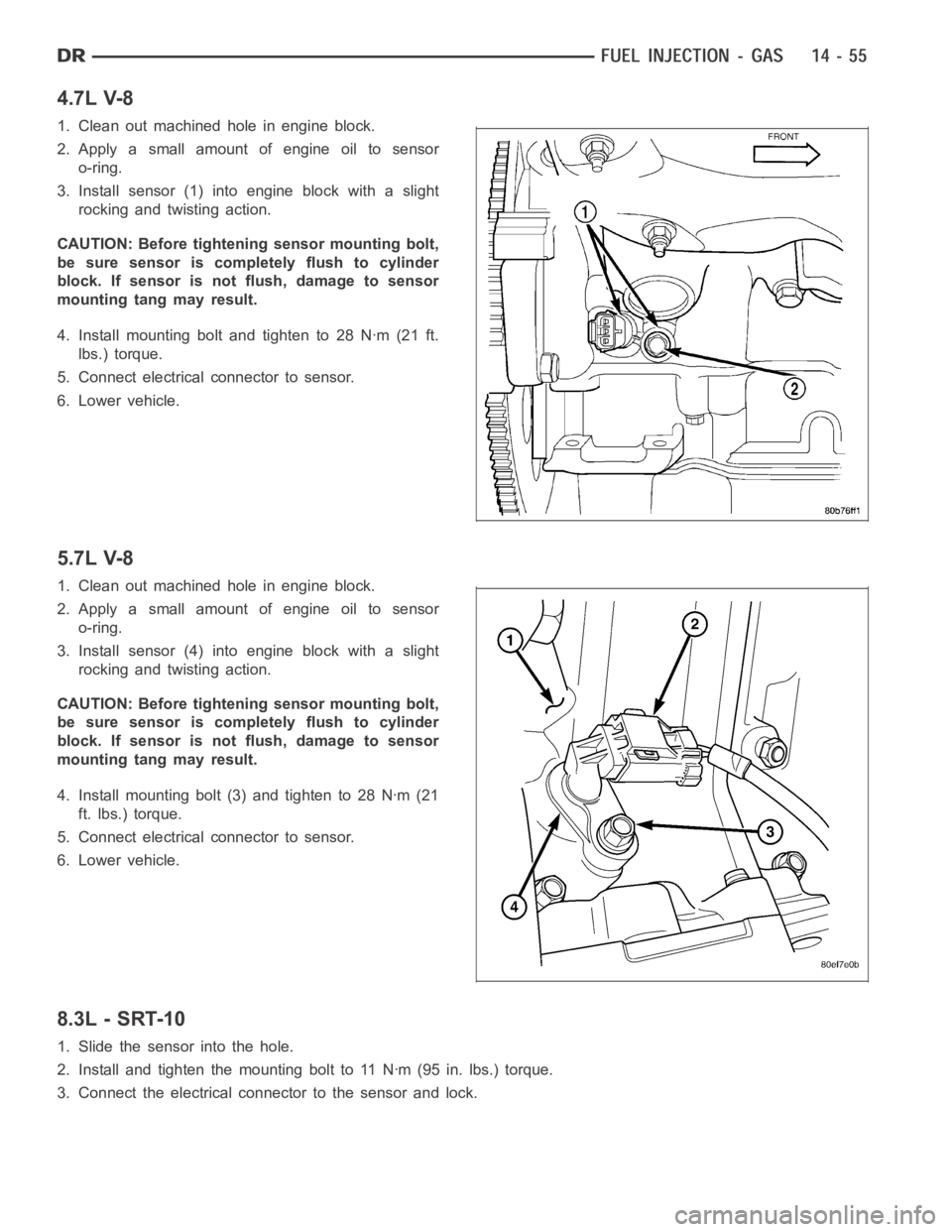
4.7L V-8
1. Clean out machined hole in engine block.
2. Apply a small amount of engine oil to sensor
o-ring.
3. Install sensor (1) into engine block with a slight
rocking and twisting action.
CAUTION: Before tightening sensor mounting bolt,
be sure sensor is completely flush to cylinder
block. If sensor is not flush, damage to sensor
mounting tang may result.
4. Install mounting bolt and tighten to 28 Nꞏm (21 ft.
lbs.) torque.
5. Connect electrical connector to sensor.
6. Lower vehicle.
5.7L V-8
1. Clean out machined hole in engine block.
2. Apply a small amount of engine oil to sensor
o-ring.
3. Install sensor (4) into engine block with a slight
rocking and twisting action.
CAUTION: Before tightening sensor mounting bolt,
be sure sensor is completely flush to cylinder
block. If sensor is not flush, damage to sensor
mounting tang may result.
4. Install mounting bolt (3) and tighten to 28 Nꞏm (21
ft. lbs.) torque.
5. Connect electrical connector to sensor.
6. Lower vehicle.
8.3L - SRT-10
1. Slide the sensor into the hole.
2. Install and tighten the mounting bolt to 11 Nꞏm (95 in. lbs.) torque.
3. Connect the electrical connector to the sensor and lock.
Page 2294 of 5267
Battery voltage (12 volts +) is supplied to the injectors through the ASD relay. The ASD relay will shut-down the 12
volt power source to the fuel injectors if the PCM senses the ignition is on,but the engine is not running. This
occurs after the engine has not been running for approximately 1.8 seconds.
The PCM determines injector on-time (pulse width) based on various inputs.
REMOVAL
3.7/4.7/ 5.7L
1. Remove fuel rail. (Refer to 14 - FUEL SYSTEM/
FUEL DELIVERY/FUEL RAIL - REMOVAL)
2. Disconnect clip(s) that retain fuel injector(s) to fuel
rail (2).
8.3L - SRT-10
1. Release fuel system pressure. Refer to Fuel Pres-
sure Release Procedure in this section.
2. Remove the battery cover and disconnect negative
battery cable.
3. Remove the air cleaner assembly, refer to the
Engine/Air Intake System/Air Cleaner Housing for
more information.
4. Disconnect the electrical connector to the MAP
sensor and Coolant Temperature sensor.
Page 2297 of 5267

12. Remove the fuel injector from the fuel rail.
INSTALLATION
3.7/ 4.7/ 5.7L
1. Install fuel injector(s) into fuel rail assembly and install retainingclip(s).
2. If same injector(s) is being reinstalled, install new O-ring(s).
3. Apply a small amount of clean engine oil to each injector O-ring. This will aid in installation.
4. Install fuel rail. (Refer to 14 - FUEL SYSTEM/FUEL DELIVERY/FUEL RAIL - INSTALLATION)
5. Start engine and check for fuel leaks.
8.3L - SRT-10
1. Install the fuel injectors to the fuel rail.
2. Install fuel rail under throttle body.
3. Apply a light coating of clean engine oiltotheO-ringonthenozzleendofeach injector.
4. Insert fuel injector nozzles into openings in intake manifold. Seat theinjectors in place. Tighten fuel rail bolts to
12 Nꞏm (105 in. lbs.).
5. Attach electrical connectors to fuel injectors.
6. Connect the electrical connector to the MAP sensor and Coolant Temperature sensor.
7. Connect the electrical connector to the TPS and Idle Air Control.
8. Install the wiring harness to the wiring clips under the throttle body.
9. Connect fuel supply tube to fuel rail. Refer to Quick Connect Fittings inthe Fuel Delivery section
10. Install the negative battery cable and install the battery cover.
11. Install the air cleaner assembly, refer to the Engine/Air Intake System/Air Cleaner Housing for more information.
12. Use the DRBIII
scan tool ASD Fuel System Test to pressurize the fuel system. Check for leaks.
Page 2305 of 5267
SENSOR - INLET AIR TEMPERATURE
REMOVAL — 8.3L
NOTE: Take care not to damage the thermister pill
when removing the sensor.
1. Remove the battery cover and disconnect the neg-
ative battery cable.
2. Disconnect the electrical connector from the inlet
temperature sensor.
3. Remove sensor from inlet hose.
INSTALLATION
NOTE: Take care not to damage the open ther-
mister pill when installing the sensor.
1. Install sensor , use a little water to aid in insertion
of sensor.
2. Make sure that the rib on the sensor matches up
with the rib on the inlet hose. The thermister pill
shouldbeindirectcontactwiththeinletairstream.
3. Connect the electrical connector.
4. Connect the negative battery cable and install bat-
tery cover.
Page 2306 of 5267
SENSOR-INTAKE AIR TEMPERATURE
DESCRIPTION
3.7L V-6
The 2-wire Intake Manifold Air Temperature (IAT) sen-
sor (1) is installed in the intake manifold with the sen-
sor element extending into the air stream.
The IAT sensor is a two-wire Negative Thermal Coef-
ficient (NTC) sensor. Meaning, as intake manifold tem-
perature increases, resistance (voltage) in the sensor
decreases. As temperature decreases, resistance
(voltage) in the sensor increases.
4.7L V-8
The 2-wire Intake Manifold Air Temperature (IAT) sen-
sor (3) is installed in the intake manifold with the sen-
sor element extending into the air stream.
The IAT sensor is a two-wire Negative Thermal Coef-
ficient (NTC) sensor. Meaning, as intake manifold tem-
perature increases, resistance (voltage) in the sensor
decreases. As temperature decreases, resistance
(voltage) in the sensor increases.
Page 2307 of 5267

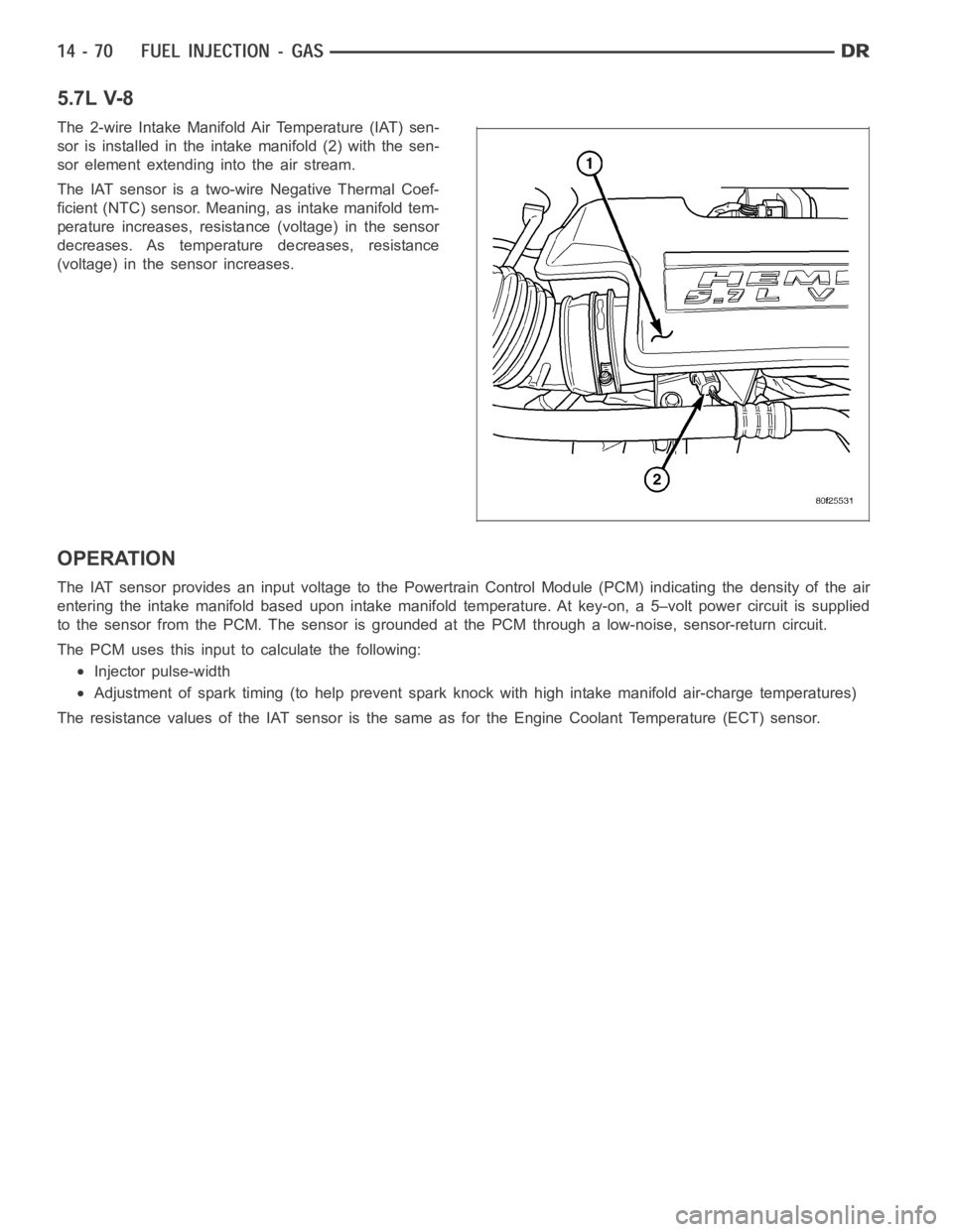
5.7L V-8
The 2-wire Intake Manifold Air Temperature (IAT) sen-
sor is installed in the intake manifold (2) with the sen-
sor element extending into the air stream.
The IAT sensor is a two-wire Negative Thermal Coef-
ficient (NTC) sensor. Meaning, as intake manifold tem-
perature increases, resistance (voltage) in the sensor
decreases. As temperature decreases, resistance
(voltage) in the sensor increases.
OPERATION
The IAT sensor provides an input voltage to the Powertrain Control Module (PCM) indicating the density of the air
entering the intake manifold based upon intake manifold temperature. At key-on, a 5–volt power circuit is supplied
to the sensor from the PCM. The sensor is grounded at the PCM through a low-noise, sensor-return circuit.
The PCM uses this input to calculate the following:
Injector pulse-width
Adjustment of spark timing (to help prevent spark knock with high intake manifold air-charge temperatures)
The resistance values of the IAT sensor is the same as for the Engine CoolantTemperature (ECT) sensor.