Page 2245 of 5267
SPECIAL TOOLS
FUEL SYSTEM
TEST KIT, FUEL PRESSURE #5069
ADAPTERS, FUEL PRESSURE TEST - #6539
AND/OR #6631
LOCKRING REMOVER/INSTALLER #9340
SPANNER WRENCH - #6856
FITTING, AIR METERING - #6714
O2S (OXYGEN SENSOR) REMOVER/INSTALLER -
#C-4907
Page 2247 of 5267
SENSOR - FUEL LEVEL SENDING UNIT
DESCRIPTION
The fuel gauge sending unit (fuel level sensor) is attached to the side of the fuel pump module. The sending unit
consists of a float, an arm, and a variable resistor track (card).
OPERATION
The fuel pump module has 4 different circuits (wires). Two of these circuits are used for the fuel gauge sending unit
for fuel gauge operation, and for certain OBD II emission requirements. The other 2 wires are used for electric fuel
pump operation.
For Fuel Gauge Operation:A constant current source is supplied to the resistor track on the fuel gauge sending
unit. This is fed directly from the Powertrain Control Module (PCM).NOTE: For diagnostic purposes, this 12V
power source can only be verified with the circuit opened (fuel pump moduleelectrical connector
unplugged). With the connectors plugged, output voltages will vary from about 0.6 volts at FULL, to about
8.6 volts at EMPTY (about 8.6 volts at EMPTY for Jeep models, and about 7.0 volts at EMPTY for Dodge
Truck models).The resistor track is used to vary the voltage (resistance) depending on fuel tank float level. As fuel
level increases, the float and arm move up, which decreases voltage. As fuel level decreases, the float and arm
move down, which increases voltage. The varied voltage signal is returnedback to the PCM through the sensor
return circuit.
Both of the electrical circuits between the fuel gauge sending unit and thePCM are hard-wired (not multi-plexed).
After the voltage signal is sent from the resistor track, and back to the PCM, the PCM will interpret the resistance
(voltage) data and send a message across the multi-plex bus circuits to theinstrument panel cluster. Here it is
translated into the appropriate fuel gauge level reading. Refer to Instrument Panel for additional information.
For OBD II Emission Monitor Requirements:The PCM will monitor the voltage output sent from the resistor track
on the sending unit to indicate fuel level. The purpose of this feature is toprevent the OBD II system from recording/
setting false misfire and fuel systemmonitor diagnostic trouble codes. The feature is activated if the fuel level in the
tank is less than approximately 15 percent of its rated capacity. If equipped with a Leak Detection Pump (EVAP
system monitor), this feature will also be activated if the fuel level in the tank is more than approximately 85 percent
of its rated capacity.
REMOVAL
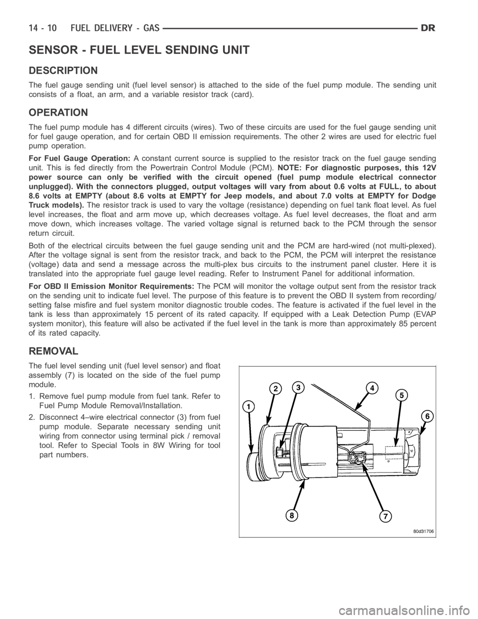
The fuel level sending unit (fuel level sensor) and float
assembly (7) is located on the side of the fuel pump
module.
1. Remove fuel pump module from fuel tank. Refer to
Fuel Pump Module Removal/Installation.
2. Disconnect 4–wire electrical connector (3) from fuel
pump module. Separate necessary sending unit
wiring from connector using terminal pick / removal
tool. Refer to Special Tools in 8W Wiring for tool
part numbers.
Page 2257 of 5267
MODULE - FUEL PUMP
DESCRIPTION
The fuel pump module assembly is located on the top of the fuel tank. The complete assembly contains the fol-
lowing components:
A combination fuel filter/fuel pressure regulator
A separate fuel pick-up, or inlet filter
An electric fuel pump
Alockringtoretainpumpmoduletotank
A soft gasket between tank flange and module
A fuel gauge sending unit (fuel level sensor)
Fuel line connection
The fuel gauge sending unit may be serviced separately. If the electrical fuel pump, primary inlet filter, fuel filter or
fuel pressure regulator require service, the fuel pump module must be replaced.
OPERATION
Refer to Fuel Pump, Inlet Filter, Fuel Filter / Fuel Pressure Regulator andFuel Gauge Sending Unit.
REMOVAL
WARNING: The fuel system may be under a constant pressure (even with the engine off). Before servicing
the fuel pump module, the fuel system pressure must be released.
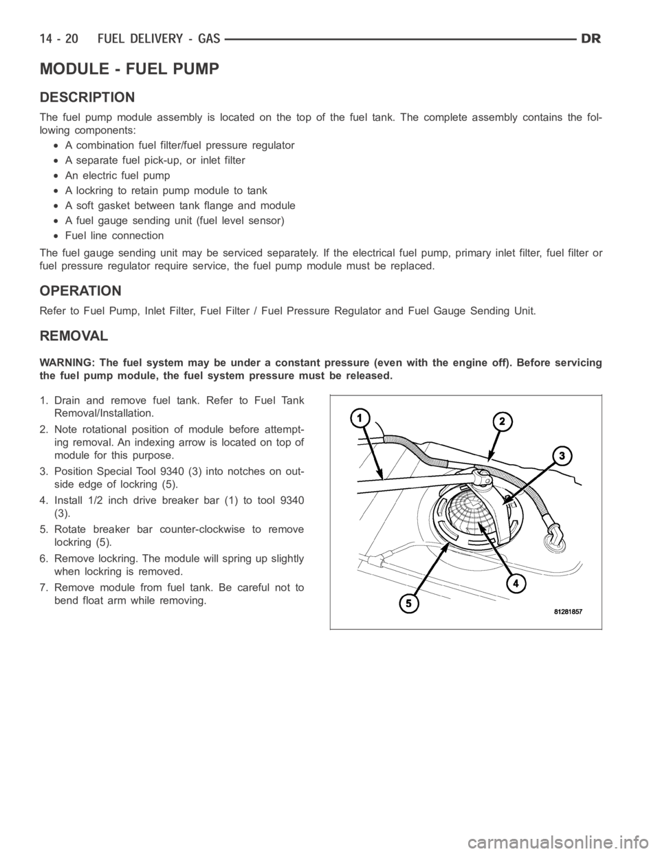
1. Drain and remove fuel tank. Refer to Fuel Tank
Removal/Installation.
2. Note rotational position of module before attempt-
ing removal. An indexing arrow is located on top of
module for this purpose.
3. Position Special Tool 9340 (3) into notches on out-
side edge of lockring (5).
4. Install 1/2 inch drive breaker bar (1) to tool 9340
(3).
5. Rotate breaker bar counter-clockwise to remove
lockring (5).
6. Remove lockring. The module will spring up slightly
when lockring is removed.
7. Remove module from fuel tank. Be careful not to
bend float arm while removing.
Page 2259 of 5267
RAIL - FUEL
DESCRIPTION
The fuel injector rail is used to mount the fuel injectors to the engine.
OPERATION
High pressure from the fuel pump is routed to the fuel rail. The fuel rail then supplies the necessary fuel to each
individual fuel injector.
A quick-connect fitting with a safety latch clip is used to attach the fuel linetothefuelrail.
The fuel rail is not repairable.
CAUTION: The left and right sections of the fuel rail are connected with either a flexible connecting hose, or
joints. Do not attempt to separate the rail halves at these connecting hoseor joints. Due to the design of
the connecting hose or joint, it does not use any clamps. Never attempt to install a clamping device of any
kind to the hose or joint. When removing the fuel rail assembly for any reason, be careful not to bend or
kink the connecting hose or joint.
REMOVAL
3.7L V-6
WARNING: The fuel system is under constant pressure even with engine off. Before servicing fuel rail, fuel
system pressure must be released.
CAUTION: The left and right fuel rails are replaced as an assembly. Do not attempt to separate rail halves
at connector tubes. Due to design of tubes, it does not use any clamps. Neverattempt to install a clamping
device of any kind to tubes. When removing fuel rail assembly for any reason, be careful not to bend or
kink tubes.
1. Remove fuel tank filler tube cap.
2. Perform Fuel System Pressure Release Procedure.
(Refer to 14 - FUEL SYSTEM/FUEL DELIVERY -
STANDARD PROCEDURE)
3. Remove negative battery cable at battery.
4. Remove air duct at throttle body air box.
5. Remove air box at throttle body.
6. Remove air resonator mounting bracket at front of
throttle body (2 bolts).
7. Disconnect fuel line latch clip and fuel line at fuel
rail. A special tool will be necessary for fuel line
disconnection. (Refer to 14 - FUEL SYSTEM/FUEL
DELIVERY/QUICK CONNECT FITTING - STAN-
DARD PROCEDURE)
8. Remove necessary vacuumlines at throttle body.
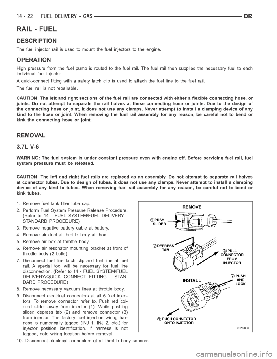
9. Disconnect electrical connectors at all 6 fuel injec-
tors. To remove connector refer to. Push red col-
ored slider away from injector (1). While pushing
slider, depress tab (2) and remove connector (3)
from injector. The factory fuel injection wiring har-
ness is numerically tagged (INJ 1, INJ 2, etc.) for
injector position identification. If harness is not
tagged, note wiring location before removal.
10. Disconnect electrical connectors at all throttle body sensors.
Page 2261 of 5267
10. Disconnect electrical connectors at all throttle body sensors.
11. Remove 8 ignition coils. (Refer to 8 - ELECTRICAL/IGNITION CONTROL/IGNITION COIL - REMOVAL)
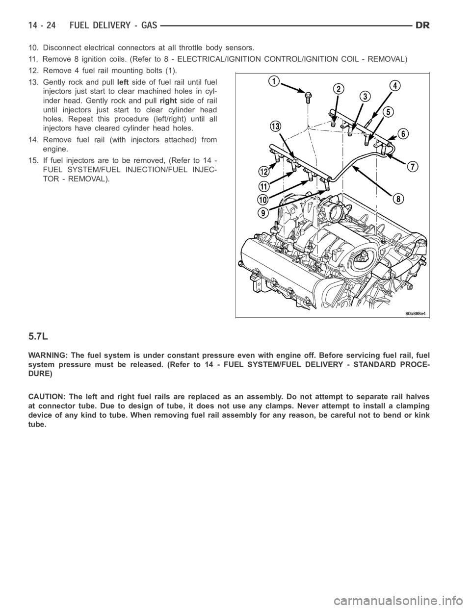
12. Remove 4 fuel rail mounting bolts (1).
13. Gently rock and pullleftside of fuel rail until fuel
injectors just start to clear machined holes in cyl-
inder head. Gently rock and pullrightside of rail
until injectors just start to clear cylinder head
holes. Repeat this procedure (left/right) until all
injectors have cleared cylinder head holes.
14. Remove fuel rail (with injectors attached) from
engine.
15. If fuel injectors are to be removed, (Refer to 14 -
FUEL SYSTEM/FUEL INJECTION/FUEL INJEC-
TOR - REMOVAL).
5.7L
WARNING: The fuel system is under constant pressure even with engine off. Before servicing fuel rail, fuel
system pressure must be released. (Refer to 14 - FUEL SYSTEM/FUEL DELIVERY- STANDARD PROCE-
DURE)
CAUTION: The left and right fuel rails are replaced as an assembly. Do not attempt to separate rail halves
at connector tube. Due to design of tube, it does not use any clamps. Never attempt to install a clamping
device of any kind to tube. When removing fuel rail assembly for any reason,be careful not to bend or kink
tube.
Page 2262 of 5267
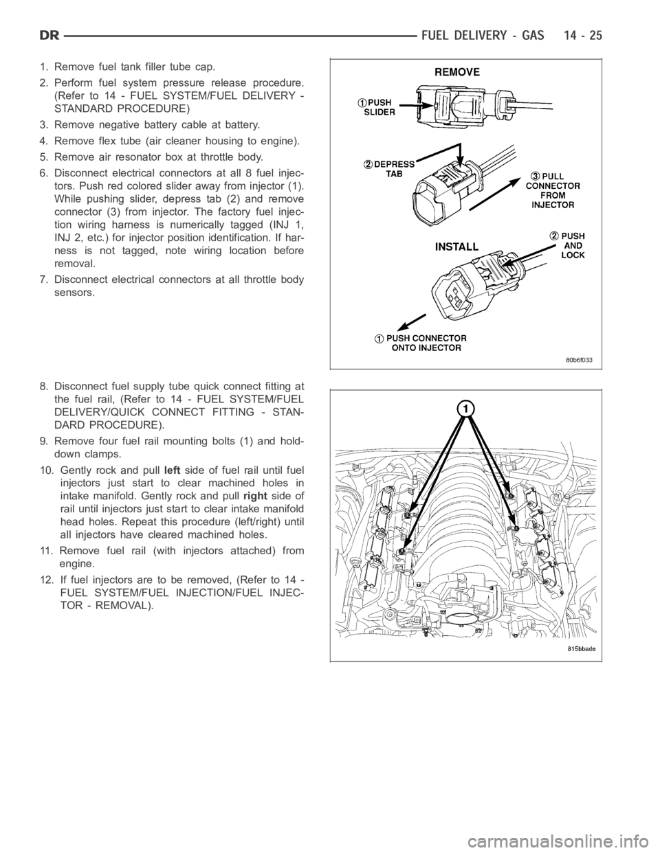
1. Remove fuel tank filler tube cap.
2. Perform fuel system pressure release procedure.
(Refer to 14 - FUEL SYSTEM/FUEL DELIVERY -
STANDARD PROCEDURE)
3. Remove negative battery cable at battery.
4. Remove flex tube (air cleaner housing to engine).
5. Remove air resonator box at throttle body.
6. Disconnect electrical connectors at all 8 fuel injec-
tors. Push red colored slider away from injector (1).
While pushing slider, depress tab (2) and remove
connector (3) from injector. The factory fuel injec-
tion wiring harness is numerically tagged (INJ 1,
INJ 2, etc.) for injector position identification. If har-
ness is not tagged, note wiring location before
removal.
7. Disconnect electrical connectors at all throttle body
sensors.
8. Disconnect fuel supply tube quick connect fitting at
the fuel rail, (Refer to14 - FUEL SYSTEM/FUEL
DELIVERY/QUICK CONNECT FITTING - STAN-
DARD PROCEDURE).
9. Remove four fuel rail mounting bolts (1) and hold-
down clamps.
10. Gently rock and pullleftside of fuel rail until fuel
injectors just start to clear machined holes in
intake manifold. Gently rock and pullrightside of
rail until injectors just start to clear intake manifold
head holes. Repeat this procedure (left/right) until
all injectors have cleared machined holes.
11. Remove fuel rail (with injectors attached) from
engine.
12. If fuel injectors are to be removed, (Refer to 14 -
FUEL SYSTEM/FUEL INJECTION/FUEL INJEC-
TOR - REMOVAL).
Page 2263 of 5267
8.3L - SRT-10
1. Disconnect the electrical connector to the MAP
sensor (2) and Coolant Temperature sensor (3).
2. Release fuel system pressure. Refer to Fuel Pres-
sure Release Procedure in this section.
3. Disconnect negative battery cable.
4. Remove the air cleaner assembly, refer to the
Engine/Air Intake System/Air Cleaner Housing for
more information.
5. Disconnect the electrical connector to the TPS (1)
and Idle Air Control.
Page 2270 of 5267
6. Connect the electrical connector to the MAP sensor and Coolant Temperature sensor.
7. Connect the electrical connector to the TPS and Idle Air Control.
8. Install the wiring harness to the wiring clips under the throttle body.
9. Connect fuel supply tube to fuel rail. Refer to Quick Connect Fittings inthe Fuel Delivery section.
10. Install the negative battery cable.
11. Install the air cleaner assembly, refer to the Engine/Air Intake System/Air Cleaner Housing for more information.
12. Use the DRBIII
scan tool ASD Fuel System Test to pressurize the fuel system. Check for leaks.