2006 DODGE RAM SRT-10 light
[x] Cancel search: lightPage 4345 of 5267
CODE FAMILY NAME COMMON TRADE NAME TYPICAL APPLICATION
MPU FOAM POLYURETHANE MPU SPOILERS
PE POLYETHYLENE ALATHON, DYLAN,
LUPOLEN, MARLEX—
PP POLYPROPYLENE
(BLENDS)NORYL, AZDEL, MARLOX,
DYLON, PRAVEXINNER FENDER, SPOILERS,
KICK PANELS
PP/EPDM PP/EPDM ALLOY PP/EPDM SPOILERS, GRILLES
PUR POLYURETHANE COLONELS, PUR, PU FASCIAS, BUMPERS
PUR/PC PUR/PC ALLOY TEXIN BUMPERS
PVC POLYVINYL CHLORIDE APEX, GEON, VINYLITE BODY MOLDINGS, WIRE
INSULATION, STEERING
WHEELS
RIM REACTION INJECTED
MOLDED POLYURETHANERIM, BAYFLEX FRONT FASCIAS, MODULAR
WINDOWS
RRIM REINFORCED REACTION
INJECTED MOLDEDPUR, RRIM FASCIAS, BODY PANELS,
BODY TRIMS
TPE THERMO POLYETHYLENE TPE, HYTREL, BEXLOY-V FASCIAS, BUMPERS,
CLADDINGS
TPO THERMOPOLYOLEFIN POLYTROPE, RENFLEX,
SANTOPRENE, VISAFLEX,
ETA, APEX, TPO, SHIELDS,
CLADDINGSBUMPERS, END CAPS,
TELCAR, RUBBER, STRIPS,
SIGHT, INTERIOR B POST
TPP THERMO-POLYPROPYLENE TPP BUMPERS
TPU THERMOPOLYURETHANE,
POLYESTERTPU, HYTREL, TEXIN,
ESTANEBUMPERS, BODY SIDE,
MOLDINGS, FENDERS,
FASCIAS
PANEL SECTIONING
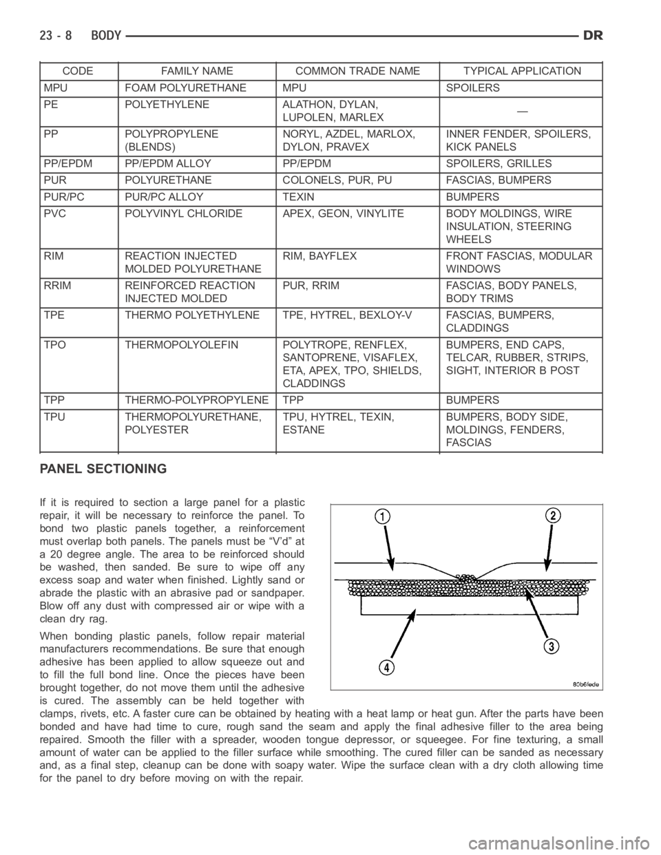
If it is required to section a large panel for a plastic
repair, it will be necessary to reinforce the panel. To
bond two plastic panels together, a reinforcement
must overlap both panels. The panels must be “V’d” at
a 20 degree angle. The area to be reinforced should
be washed, then sanded. Be sure to wipe off any
excess soap and water when finished. Lightly sand or
abrade the plastic with an abrasive pad or sandpaper.
Blow off any dust with compressed air or wipe with a
clean dry rag.
When bonding plastic panels, follow repair material
manufacturers recommendations. Be sure that enough
adhesive has been applied to allow squeeze out and
to fill the full bond line. Once the pieces have been
brought together, do not move them until the adhesive
is cured. The assembly can be held together with
clamps, rivets, etc. A faster cure can be obtained by heating with a heat lamp or heat gun. After the parts have been
bonded and have had time to cure, rough sand the seam and apply the final adhesive filler to the area being
repaired. Smooth the filler with a spreader, wooden tongue depressor, or squeegee. For fine texturing, a small
amount of water can be applied to the filler surface while smoothing. The cured filler can be sanded as necessary
and, as a final step, cleanup can be done with soapy water. Wipe the surface clean with a dry cloth allowing time
for the panel to dry before moving on with the repair.
Page 4426 of 5267
CARGO BOX
REMOVAL
NOTE: Long cargo box shown in illustration. Short
cargo box similar.
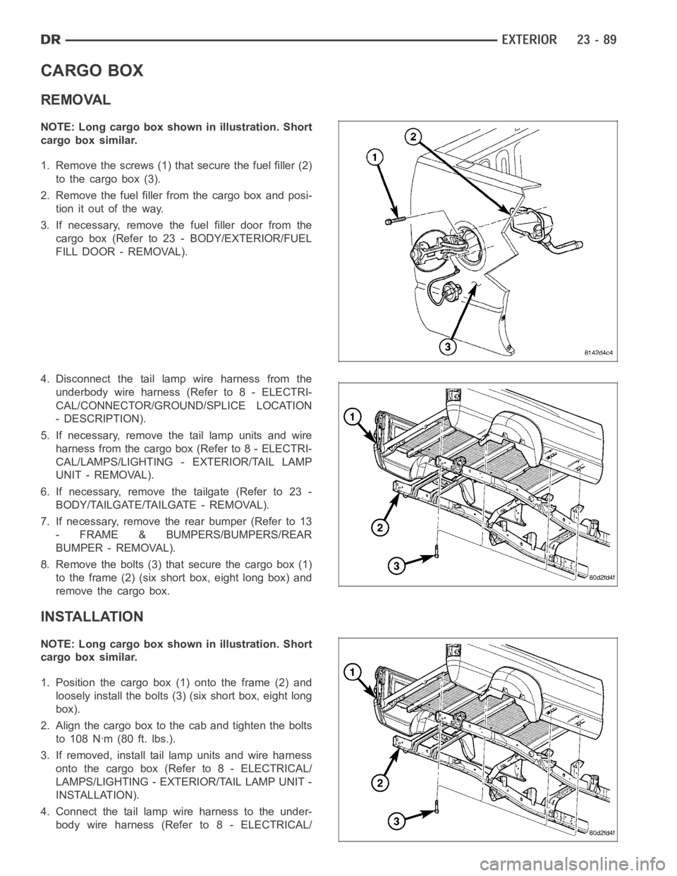
1. Remove the screws (1) that secure the fuel filler (2)
to the cargo box (3).
2. Remove the fuel filler from the cargo box and posi-
tionitoutoftheway.
3. If necessary, remove the fuel filler door from the
cargo box (Refer to 23 - BODY/EXTERIOR/FUEL
FILL DOOR - REMOVAL).
4. Disconnect the tail lamp wire harness from the
underbody wire harness (Refer to 8 - ELECTRI-
CAL/CONNECTOR/GROUND/SPLICE LOCATION
- DESCRIPTION).
5. If necessary, remove the tail lamp units and wire
harness from the cargo box (Refer to 8 - ELECTRI-
CAL/LAMPS/LIGHTING - EXTERIOR/TAIL LAMP
UNIT - REMOVAL).
6. If necessary, remove the tailgate (Refer to 23 -
BODY/TAILGATE/TAILGATE - REMOVAL).
7. If necessary, remove the rear bumper (Refer to 13
- FRAME & BUMPERS/BUMPERS/REAR
BUMPER - REMOVAL).
8. Remove the bolts (3) that secure the cargo box (1)
to the frame (2) (six short box, eight long box) and
remove the cargo box.
INSTALLATION
NOTE: Long cargo box shown in illustration. Short
cargo box similar.
1. Position the cargo box (1) onto the frame (2) and
loosely install the bolts (3) (six short box, eight long
box).
2. Align the cargo box to the cab and tighten the bolts
to 108 Nꞏm (80 ft. lbs.).
3. If removed, install tail lamp units and wire harness
onto the cargo box (Refer to 8 - ELECTRICAL/
LAMPS/LIGHTING - EXTERIOR/TAIL LAMP UNIT -
INSTALLATION).
4. Connect the tail lamp wire harness to the under-
body wire harness (Refer to 8 - ELECTRICAL/
Page 4432 of 5267
FRONT FENDER
REMOVAL
1. Remove the radio antenna (Refer to 8 - ELECTRI-
CAL/AUDIO/ANTENNA BODY & CABLE -
REMOVAL).
2. Remove the battery tray (depending on fender
beingserviced)(Referto8-ELECTRICAL/BAT-
TERY SYSTEM/TRAY - REMOVAL).
3. Remove the cowl grille (Refer to 23 - BODY/EXTE-
RIOR/COWL GRILLE - REMOVAL).
4. Remove the headlamp unit (Refer to 8 - ELECTRI-
CAL/LAMPS/LIGHTING - EXTERIOR/HEADLAMP
UNIT - REMOVAL).
5. Remove the wheelhouse splash shield (Refer to 23
- BODY/EXTERIOR/FRONT WHEELHOUSE
SPLASH SHIELD - REMOVAL).
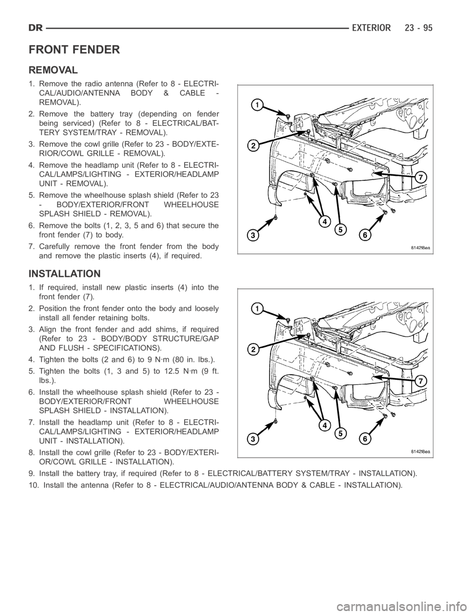
6. Remove the bolts (1, 2, 3, 5 and 6) that secure the
front fender (7) to body.
7. Carefully remove the front fender from the body
and remove the plastic inserts (4), if required.
INSTALLATION
1. If required, install new plastic inserts (4) into the
front fender (7).
2. Position the front fender onto the body and loosely
install all fender retaining bolts.
3. Align the front fender and add shims, if required
(Refer to 23 - BODY/BODY STRUCTURE/GAP
AND FLUSH - SPECIFICATIONS).
4. Tighten the bolts (2 and 6) to 9 Nꞏm (80 in. lbs.).
5. Tighten the bolts (1, 3 and 5) to 12.5 Nꞏm (9 ft.
lbs.).
6. Install the wheelhouse splash shield (Refer to 23 -
BODY/EXTERIOR/FRONT WHEELHOUSE
SPLASH SHIELD - INSTALLATION).
7. Install the headlamp unit (Refer to 8 - ELECTRI-
CAL/LAMPS/LIGHTING - EXTERIOR/HEADLAMP
UNIT - INSTALLATION).
8. Install the cowl grille (Refer to 23 - BODY/EXTERI-
OR/COWL GRILLE - INSTALLATION).
9. Install the battery tray, if required (Refer to 8 - ELECTRICAL/BATTERY SYSTEM/TRAY - INSTALLATION).
10. Install the antenna (Refer to 8 - ELECTRICAL/AUDIO/ANTENNA BODY & CABLE - INSTALLATION).
Page 4436 of 5267
REAR FENDER-QUAD CAB MODELS
REMOVAL
1. Disconnect and isolate the negative battery cable.
2. Remove the tail lamp unit (Refer to 8 - ELECTRI-
CAL/LAMPS/LIGHTING - EXTERIOR/TAIL LAMP
UNIT - REMOVAL).
3. Remove the rear wheelhouse splash shield (Refer
to 23 - BODY/EXTERIOR/REAR WHEELHOUSE
SPLASH SHIELD - REMOVAL).
4. Remove the two marker lamp units from the rear
fender (Refer to 8 - ELECTRICAL/LAMPS/LIGHT-
ING - EXTERIOR/MARKER LAMP UNIT -
REMOVAL).
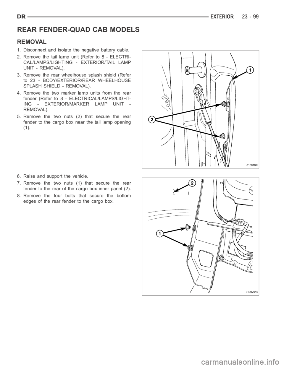
5. Remove the two nuts (2) that secure the rear
fender to the cargo box near the tail lamp opening
(1).
6. Raise and support the vehicle.
7. Remove the two nuts (1) that secure the rear
fender to the rear of the cargo box inner panel (2).
8. Remove the four bolts that secure the bottom
edges of the rear fender to the cargo box.
Page 4439 of 5267
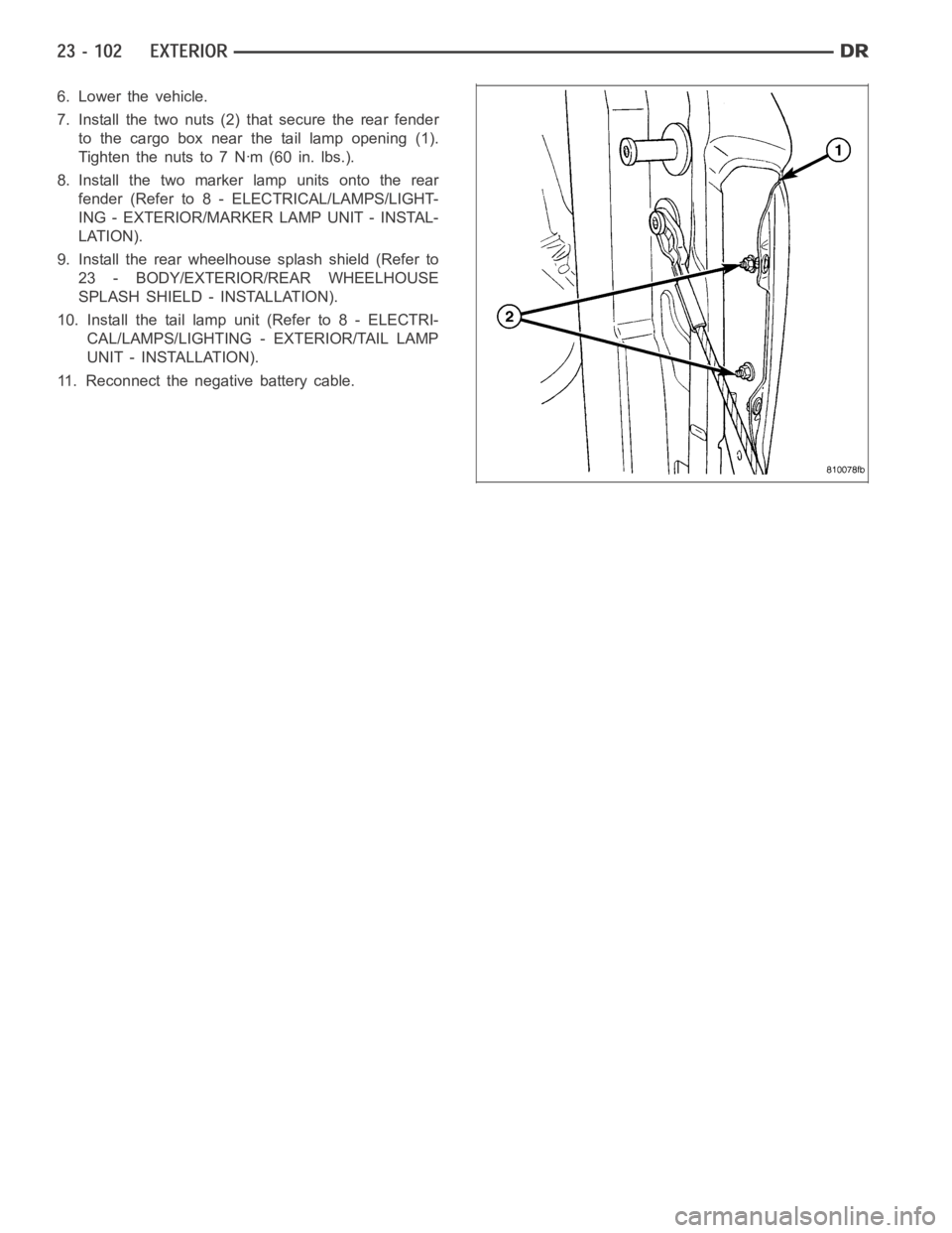
6. Lower the vehicle.
7. Install the two nuts (2) that secure the rear fender
to the cargo box near the tail lamp opening (1).
Tightenthenutsto7Nꞏm(60in.lbs.).
8. Install the two marker lamp units onto the rear
fender (Refer to 8 - ELECTRICAL/LAMPS/LIGHT-
ING - EXTERIOR/MARKER LAMP UNIT - INSTAL-
LATION).
9. Install the rear wheelhouse splash shield (Refer to
23 - BODY/EXTERIOR/REAR WHEELHOUSE
SPLASH SHIELD - INSTALLATION).
10. Install the tail lamp unit (Refer to 8 - ELECTRI-
CAL/LAMPS/LIGHTING - EXTERIOR/TAIL LAMP
UNIT - INSTALLATION).
11. Reconnect the negative battery cable.
Page 4469 of 5267
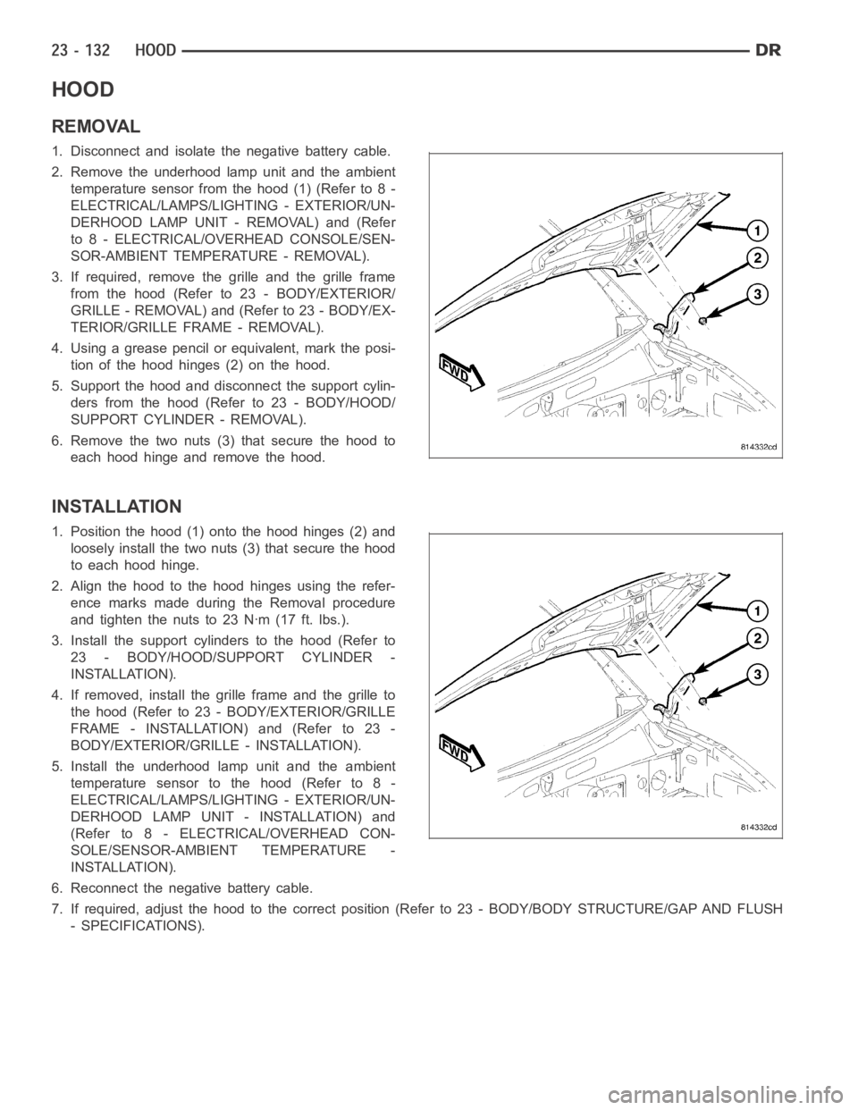
HOOD
REMOVAL
1. Disconnect and isolate the negative battery cable.
2. Remove the underhood lamp unit and the ambient
temperature sensor from the hood (1) (Refer to 8 -
ELECTRICAL/LAMPS/LIGHTING - EXTERIOR/UN-
DERHOOD LAMP UNIT - REMOVAL) and (Refer
to 8 - ELECTRICAL/OVERHEAD CONSOLE/SEN-
SOR-AMBIENT TEMPERATURE - REMOVAL).
3. If required, remove the grille and the grille frame
from the hood (Refer to 23 - BODY/EXTERIOR/
GRILLE - REMOVAL) and (Refer to 23 - BODY/EX-
TERIOR/GRILLE FRAME - REMOVAL).
4. Using a grease pencil or equivalent, mark the posi-
tion of the hood hinges (2) on the hood.
5. Support the hood and disconnect the support cylin-
ders from the hood (Refer to 23 - BODY/HOOD/
SUPPORT CYLINDER - REMOVAL).
6. Remove the two nuts (3) that secure the hood to
each hood hinge and remove the hood.
INSTALLATION
1. Position the hood (1) onto the hood hinges (2) and
loosely install the two nuts (3) that secure the hood
to each hood hinge.
2. Align the hood to the hood hinges using the refer-
ence marks made during the Removal procedure
and tighten the nuts to 23 Nꞏm (17 ft. lbs.).
3. Install the support cylinders to the hood (Refer to
23 - BODY/HOOD/SUPPORT CYLINDER -
INSTALLATION).
4. If removed, install the grille frame and the grille to
the hood (Refer to 23 - BODY/EXTERIOR/GRILLE
FRAME - INSTALLATION) and (Refer to 23 -
BODY/EXTERIOR/GRILLE - INSTALLATION).
5. Install the underhood lamp unit and the ambient
temperature sensor to the hood (Refer to 8 -
ELECTRICAL/LAMPS/LIGHTING - EXTERIOR/UN-
DERHOOD LAMP UNIT - INSTALLATION) and
(Refer to 8 - ELECTRICAL/OVERHEAD CON-
SOLE/SENSOR-AMBIENT TEMPERATURE -
INSTALLATION).
6. Reconnect the negative battery cable.
7. If required, adjust the hood to the correct position (Refer to 23 - BODY/BODY STRUCTURE/GAP AND FLUSH
- SPECIFICATIONS).
Page 4539 of 5267
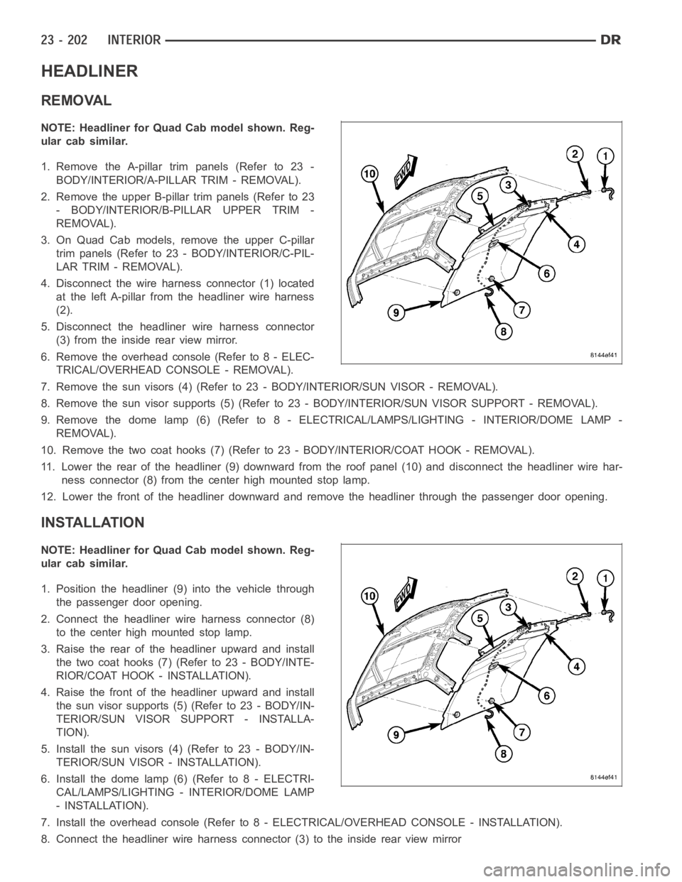
HEADLINER
REMOVAL
NOTE: Headliner for Quad Cab model shown. Reg-
ular cab similar.
1. Remove the A-pillar trim panels (Refer to 23 -
BODY/INTERIOR/A-PILLAR TRIM - REMOVAL).
2. Remove the upper B-pillar trim panels (Refer to 23
- BODY/INTERIOR/B-PILLAR UPPER TRIM -
REMOVAL).
3. On Quad Cab models, remove the upper C-pillar
trim panels (Refer to 23 - BODY/INTERIOR/C-PIL-
LAR TRIM - REMOVAL).
4. Disconnect the wire harness connector (1) located
at the left A-pillar from the headliner wire harness
(2).
5. Disconnect the headliner wire harness connector
(3) from the inside rear view mirror.
6. Remove the overhead console (Refer to 8 - ELEC-
TRICAL/OVERHEAD CONSOLE - REMOVAL).
7. Remove the sun visors (4) (Refer to 23 - BODY/INTERIOR/SUN VISOR - REMOVAL).
8. Remove the sun visor supports (5) (Refer to 23 - BODY/INTERIOR/SUN VISORSUPPORT - REMOVAL).
9. Remove the dome lamp (6) (Refer to 8 -ELECTRICAL/LAMPS/LIGHTING - INTERIOR/DOME LAMP -
REMOVAL).
10. Remove the two coat hooks (7) (Refer to 23 - BODY/INTERIOR/COAT HOOK - REMOVAL).
11. Lower the rear of the headliner (9) downward from the roof panel (10) anddisconnect the headliner wire har-
ness connector (8) from the center high mounted stop lamp.
12. Lower the front of the headliner downward and remove the headliner through the passenger door opening.
INSTALLATION
NOTE: Headliner for Quad Cab model shown. Reg-
ular cab similar.
1. Position the headliner (9) into the vehicle through
the passenger door opening.
2. Connect the headliner wire harness connector (8)
to the center high mounted stop lamp.
3. Raise the rear of the headliner upward and install
the two coat hooks (7) (Refer to 23 - BODY/INTE-
RIOR/COAT HOOK - INSTALLATION).
4. Raise the front of the headliner upward and install
the sun visor supports (5) (Refer to 23 - BODY/IN-
TERIOR/SUN VISOR SUPPORT - INSTALLA-
TION).
5. Install the sun visors (4) (Refer to 23 - BODY/IN-
TERIOR/SUN VISOR - INSTALLATION).
6. Install the dome lamp (6) (Refer to 8 - ELECTRI-
CAL/LAMPS/LIGHTING - INTERIOR/DOME LAMP
- INSTALLATION).
7. Install the overhead console (Refer to 8 - ELECTRICAL/OVERHEAD CONSOLE-INSTALLATION).
8. Connect the headliner wire harness connector (3) to the inside rear viewmirror
Page 4553 of 5267
PA I N T
SPECIFICATIONS
PA I N T C O D E S
CAUTION: Due to possible late model change of paint colors, always check each vehicle for its paint
code(s) (Refer to VEHICLE DATA/VEHICLE INFORMATION/VEHICLE CERTIFICATION LABEL - DESCRIPTION)
or (Refer to VEHICLE DATA/VEHICLE INFORMATION/BODY CODE PLATE - DESCRIPTION) and (Refer to 23 -
BODY/PAINT/PAINT CODE - DESCRIPTION).
EXTERIOR COLORS
EXTERIOR COLOR DAIMLERCHRYSLER CODE
Inferno Red Crystal Pearlcoat ARH/ARJ
Flame Red Clearcoat PR4
Light Khaki Clearcoat AJC
Atlantic Blue Pearlcoat ZBJ
Patriot Blue Pearlcoat WBT/WB7
Bright Silver Metallic Clearcoat WSB/WS2
Mineral Gray Metallic Clearcoat CDM
Black Clearcoat DX8
Bright White Clearcoat GW7
INTERIOR COLORS
INTERIOR COLOR DAIMLERCHRYSLER CODE
Medium Slate Gray D5
Khaki J3